- Table of Contents
-
- 11-Network Management and Monitoring Configuration Examples
- 01-H3C_NQA_Configuration_Examples
- 02-H3C_NTP_Configuration_Examples
- 03-H3C_SNMP_Configuration_Examples
- 04-H3C_EAA_Configuration_Examples
- 05-H3C_Mirroring_Configuration_Examples
- 06-H3C_NetStream_Configuration_Examples
- 07-H3C_sFlow_Configuration_Examples
- Related Documents
-
| Title | Size | Download |
|---|---|---|
| 05-H3C_Mirroring_Configuration_Examples | 1.03 MB |
|
|
|
H3C Mirroring Configuration Examples |
|
|
|
|
|
|
Software version: Release 7595
Document version: 6W100-20201031
Copyright © 2020 New H3C Technologies Co., Ltd. All rights reserved.
No part of this manual may be reproduced or transmitted in any form or by any means without prior written consent of New H3C Technologies Co., Ltd.
Except for the trademarks of New H3C Technologies Co., Ltd., any trademarks that may be mentioned in this document are the property of their respective owners.
The information in this document is subject to change without notice.
Contents
Example: Configuring local port mirroring
Example: Configure Layer 2 remote port mirroring (reflector port configurable)
Configuring Device A (the destination device)
Configuring Device B (the intermediate device)
Configuring Device C (the source device)
Configuring Device D (the source device)
Example: Configure Layer 2 remote port mirroring (with egress port)
Configuring Device A (the destination device)
Configuring Device B (the intermediate device)
Configuring Device C (the source device)
Configuring Device D (the source device)
Example: Configuring local flow mirroring
Example: Configuring flow mirroring in a flexible way
Configuring Device A to mirror traffic from the public servers
Configuring Device A to mirror the Internet traffic from the Marketing department
Configuring Device B to mirror traffic from the Technical department
Introduction
This document provides configuration examples of port mirroring and flow mirroring.
Prerequisites
The configuration examples in this document were created and verified in a lab environment, and all the devices were started with the factory default configuration. When you are working on a live network, make sure you understand the potential impact of every command on your network.
This document assumes that you have basic knowledge of H3C port mirroring and flow mirroring.
Example: Configuring local port mirroring
Network configuration
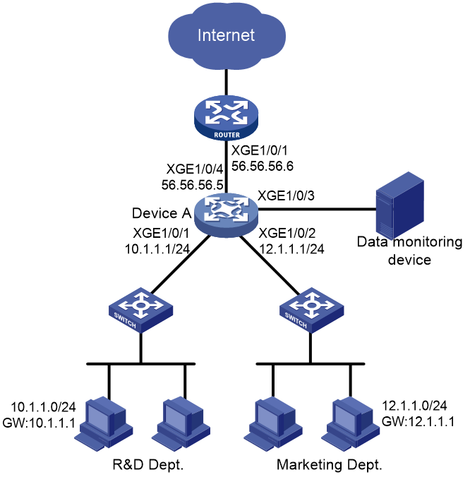
As shown in Figure 1, configure local port mirroring to monitor the Internet traffic and bidirectional traffic of the Marketing department and the Technical department.
Restrictions and guidelines
When you configure local port mirroring, follow these restrictions and guidelines:
· A local mirroring group takes effect only when you configure both source ports and the monitor port for the group. When you configure the monitor port, do not use a port of an existing mirroring group.
· Use a monitor port only for port mirroring, so the data monitoring device receives and analyzes only the mirrored traffic.
· For the correct operation of port mirroring, disable the spanning tree feature on the monitor port if it is a Layer 2 interface.
Procedures
# Assign IP address 10.1.1.1 to Ten-GigabitEthernet 1/0/1.
<DeviceA> system-view
[DeviceA] interface ten-gigabitethernet 1/0/1
[DeviceA-Ten-GigabitEthernet1/0/1] port link-mode route
[DeviceA-Ten-GigabitEthernet1/0/1] ip address 10.1.1.1 24
[DeviceA-Ten-GigabitEthernet1/0/1] quit
# Assign IP addresses to Ten-GigabitEthernet 1/0/2 and Ten-GigabitEthernet 1/0/3 in the same way 10.1.1.1 is assigned to Ten-GigabitEthernet 1/0/1. (Details not shown.)
# Create local mirroring group 1.
[DeviceA] mirroring-group 1 local
# Configure mirroring group 1 to monitor the inbound traffic of Ten-GigabitEthernet 1/0/1 and Ten-GigabitEthernet 1/0/2.
[DeviceA] mirroring-group 1 mirroring-port ten-gigabitethernet 1/0/1 ten-gigabitethernet 1/0/2 inbound
# Configure Ten-GigabitEthernet 1/0/3 as the monitor port of the mirroring group.
[DeviceA] mirroring-group 1 monitor-port ten-gigabitethernet 1/0/3
# Disable the spanning tree feature on Ten-GigabitEthernet 1/0/3.
[DeviceA] interface ten-gigabitethernet 1/0/3
[DeviceA-Ten-GigabitEthernet1/0/3] undo stp enable
[DeviceA-Ten-GigabitEthernet1/0/3] quit
Verifying the configuration
1. Display information about mirroring group 1 on Device A.
[DeviceA] display mirroring-group 1
Mirroring group 1:
Type: Local
Status: Active
Mirroring port:
Ten-GigabitEthernet1/0/1 Inbound
Ten-GigabitEthernet1/0/2 Inbound
Monitor port: Ten-GigabitEthernet1/0/3
2. Use Wireshark for packet analysis:
# Ping 56.56.56.6 from a Technical department host (10.1.1.2). (Details not shown.)
# Use Wireshark on the data monitoring device to capture the ping packets.
Figure 2 Ping packet analysis in Wireshark
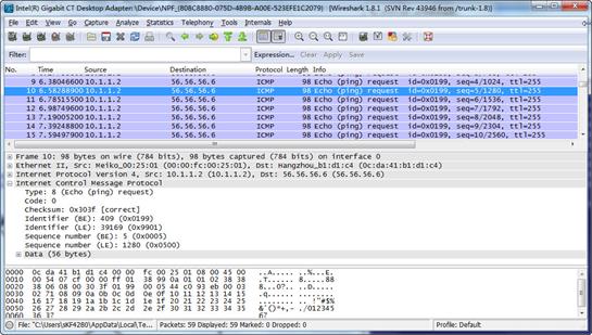
The analysis shows that the data monitoring device can monitor the packets sent from the Technical department.
Configuration files
#
mirroring-group 1 local
#
interface Ten-GigabitEthernet1/0/1
port link-mode route
ip address 10.1.1.1 255.255.255.0
mirroring-group 1 mirroring-port inbound
#
interface Ten-GigabitEthernet1/0/2
port link-mode route
ip address 12.1.1.1 255.255.255.0
mirroring-group 1 mirroring-port inbound
#
interface Ten-GigabitEthernet1/0/3
port link-mode bridge
undo stp enable
mirroring-group 1 monitor-port
#
interface Ten-GigabitEthernet1/0/4
port link-mode route
ip address 56.56.56.5 255.255.255.0
#
Example: Configure Layer 2 remote port mirroring (reflector port configurable)
Network configuration
As shown in Figure 3, configure Layer 2 remote port mirroring to monitor the outgoing traffic from the Technical department.

Analysis
To ensure correct forwarding of mirrored packets, assign the ports that connect intermediate devices to the source and destination devices to the remote probe VLAN.
Restrictions and guidelines
When you configure devices for remote port mirroring, configure them in the order of the destination device, the intermediate devices, and the source device.
When you configure the monitor port for the remote destination group on the destination device, follow these restrictions and guidelines:
· Do not use a port of an existing mirroring group.
· Use the monitor port only for port mirroring.
· For the correct operation of port mirroring, disable the spanning tree feature on the monitor port if it is a Layer 2 interface.
· For the monitor port to forward mirrored packets to the data monitoring device without VLAN tags, assign the monitor port to the remote probe VLAN as an access port.
When you configure the remote probe VLAN on the source and destination devices, follow these restrictions and guidelines:
· Use an existing static VLAN that is not in use.
· Use the remote probe VLAN for port mirroring exclusively.
· The remote mirroring groups on the source device and destination device must use the same remote probe VLAN. Use this VLAN only for the same remote mirroring group on the source device and destination device.
· Do not assign source ports of the remote source group to the remote probe VLAN.
· The port to be configured as a reflector port must be a port not in use. Do not connect a network cable to a reflector port.
· When a port is configured as a reflector port, all existing configurations of the port are cleared. You cannot configure other features on the reflector port.
· A mirroring group contains only one reflector port.
· You can configure a port as a reflector port only when the port is operating with the default duplex mode, speed, and MDI settings. You cannot change these settings for a reflector port.
Procedures
Configuring Device A (the destination device)
# Create VLANs 2 and 3.
<DeviceA> system-view
[DeviceA] vlan 2 to 3
# Create VLAN-interface 2 and assign an IP address to it.
[DeviceA] interface Vlan-interface 2
[DeviceA-Vlan-interface2] ip address 10.1.1.1 24
[DeviceA-Vlan-interface2] quit
# Create VLAN-interface 3 and assign an IP address to it.
[DeviceA] interface Vlan-interface 3
[DeviceA-Vlan-interface3] ip address 12.1.1.1 24
[DeviceA-Vlan-interface3] quit
# Configure Ten-GigabitEthernet 1/0/1 as a trunk port, and assign the port to VLANs 2, 3, and 5.
<DeviceA> system-view
[DeviceA] interface ten-gigabitethernet 1/0/1
[DeviceA-Ten-GigabitEthernet1/0/1] port link-type trunk
[DeviceA-Ten-GigabitEthernet1/0/1] port trunk permit vlan 2 3 5
[DeviceA-Ten-GigabitEthernet1/0/1] quit
# Configure Ten-GigabitEthernet 1/0/2 as a trunk port, and assign the port to VLANs 2 and 5.
[DeviceA] interface ten-gigabitethernet 1/0/2
[DeviceA-Ten-GigabitEthernet1/0/2] port link-type trunk
[DeviceA-Ten-GigabitEthernet1/0/2] port trunk permit vlan 2 5
[DeviceA-Ten-GigabitEthernet1/0/2] quit
# Create a remote destination group.
[DeviceA] mirroring-group 1 remote-destination
# Create VLAN 5.
[DeviceA] vlan 5
[DeviceA-vlan5] quit
# Configure VLAN 5 as the remote probe VLAN of the remote destination group.
[DeviceA] mirroring-group 1 remote-probe vlan 5
# Configure Ten-GigabitEthernet 1/0/3 as the monitor port of the remote destination group.
[DeviceA] mirroring-group 1 monitor-port ten-gigabitethernet 1/0/3
# Configure Ten-GigabitEthernet 1/0/3 as an access port, and assign the port to the remote probe VLAN.
[DeviceA] interface Ten-GigabitEthernet 1/0/3
[DeviceA-GigabitEthernet3/0/3] port access vlan 5
# Disable the spanning tree feature on Ten-GigabitEthernet 1/0/3.
[DeviceA-Ten-GigabitEthernet1/0/3] undo stp enable
[DeviceA-Ten-GigabitEthernet1/0/3] quit
Configuring Device B (the intermediate device)
# Create VLANs 2 and 3.
<DeviceB> system-view
[DeviceB] vlan 2 to 3
# Create VLAN 5.
[DeviceB] vlan 5
[DeviceB-vlan5] quit
# Configure Ten-GigabitEthernet 1/0/1 as a trunk port, and assign the port to VLANs 2, 3, and 5.
[DeviceB] interface ten-gigabitethernet 1/0/1
[DeviceB-Ten-GigabitEthernet1/0/1] port link-type trunk
[DeviceB-Ten-GigabitEthernet1/0/1] port trunk permit vlan 2 3 5
[DeviceB-Ten-GigabitEthernet1/0/1] quit
# Configure Ten-GigabitEthernet 1/0/2 as a trunk port, and assign the port to VLANs 2, 3, and 5.
[DeviceB] interface ten-gigabitethernet 1/0/2
[DeviceB-Ten-GigabitEthernet1/0/2] port link-type trunk
[DeviceB-Ten-GigabitEthernet1/0/2] port trunk permit vlan 2 3 5
[DeviceB-Ten-GigabitEthernet1/0/2] quit
Configuring Device C (the source device)
# Create VLANs 2 and 3.
<DeviceC> system-view
[DeviceC] vlan 2 to 3
# Assign Ten-GigabitEthernet 1/0/1 to VLAN 2.
[DeviceC] interface ten-gigabitethernet 1/0/1
[DeviceC-Ten-GigabitEthernet1/0/1] port access vlan 2
[DeviceC-Ten-GigabitEthernet1/0/1] quit
# Assign Ten-GigabitEthernet 1/0/2 to VLAN 3.
[DeviceC] interface ten-gigabitethernet 1/0/2
[DeviceC-Ten-GigabitEthernet1/0/2] port access vlan 3
[DeviceC-Ten-GigabitEthernet1/0/2] quit
# Create a remote source group.
[DeviceC] mirroring-group 1 remote-source
# Create VLAN 5.
[DeviceC] vlan 5
[DeviceC-vlan5] quit
# Configure VLAN 5 as the remote probe VLAN for the remote source group.
[DeviceC] mirroring-group 1 remote-probe vlan 5
# Configure Ten-GigabitEthernet 1/0/1 as the source port of the remote source group and the mirroring direction as inbound.
[DeviceC] mirroring-group 1 mirroring-port ten-gigabitethernet 1/0/1 inbound
# Configure Ten-GigabitEthernet 1/0/5 as the reflector port of the remote source group.
[DeviceC] mirroring-group 1 reflector-port ten-gigabitethernet 1/0/5
This operation may delete all settings made on the interface. Continue? [Y/N]: y
# Configure Ten-GigabitEthernet 1/0/3 as a trunk port, and assign the port to VLANs 2, 3, and 5.
[DeviceC] interface ten-gigabitethernet 1/0/3
[DeviceC-Ten-GigabitEthernet1/0/3] port link-type trunk
[DeviceC-Ten-GigabitEthernet1/0/3] port trunk permit vlan 2 3 5
[DeviceC-Ten-GigabitEthernet1/0/3] quit
Configuring Device D (the source device)
# Create VLAN 2.
<DeviceD> system-view
[DeviceD] vlan 2
[DeviceD-vlan2] quit
# Assign Ten-GigabitEthernet 1/0/1 to VLAN 2.
[DeviceD] interface ten-gigabitethernet 1/0/1
[DeviceD-Ten-GigabitEthernet1/0/1] port access vlan 2
[DeviceD-Ten-GigabitEthernet1/0/1] quit
# # Create remote source group 1.
[DeviceD] mirroring-group 1 remote-source
# Create VLAN 5.
[DeviceD] vlan 5
[DeviceD-vlan5] quit
# Configure VLAN 5 as the remote probe VLAN for the remote source group.
[DeviceD] mirroring-group 1 remote-probe vlan 5
# Configure Ten-GigabitEthernet 1/0/1 as the source port of the remote source group and the mirroring direction as inbound.
[DeviceD] mirroring-group 1 mirroring-port ten-gigabitethernet 1/0/1 inbound
# Configure Ten-GigabitEthernet 1/0/5 as the reflector port of the remote source group.
[DeviceD] mirroring-group 1 reflector-port ten-gigabitethernet 1/0/5
This operation may delete all settings made on the interface. Continue? [Y/N]: y
# Configure Ten-GigabitEthernet 1/0/2 as a trunk port, and assign the port to VLANs 2 and 5.
[DeviceD] interface ten-gigabitethernet 1/0/2
[DeviceD-Ten-GigabitEthernet1/0/2] port link-type trunk
[DeviceD-Ten-GigabitEthernet1/0/2] port trunk permit vlan 2 5
[DeviceD-Ten-GigabitEthernet1/0/2] quit
Verifying the configuration
1. Verify mirroring group configurations on devices:
# Display information about mirroring group 1 on Device C.
[DeviceC] display mirroring-group 1
Mirroring group 1:
Type: Remote source
Status: Active
Mirroring port:
Ten-GigabitEthernet1/0/1 Inbound
Reflector port: Ten-GigabitEthernet1/0/5
Remote probe VLAN: 5
# Display information about mirroring group 1 on Device A.
[DeviceA] display mirroring-group 1
Mirroring group 1:
Type: Remote destination
Status: Active
Monitor port: Ten-GigabitEthernet1/0/3
Remote probe VLAN: 5
2. Use Wireshark for packet analysis:
# Ping a Marketing department host (12.1.1.2) from a Technical department host (10.1.1.2). (Details not shown.)
# Use Wireshark on the data monitoring device to capture the ping packets.
Figure 4 Ping packet analysis in Wireshark
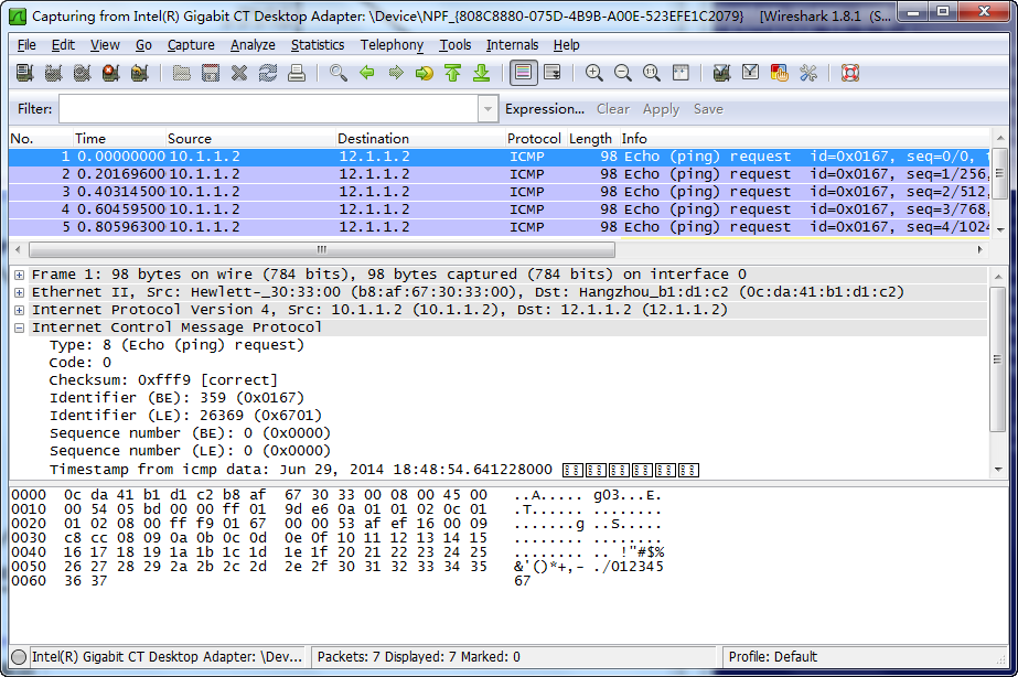
The analysis shows that the data monitoring device can monitor the outgoing traffic from the Technical department.
Configuration files
· Device A:
#
mirroring-group 1 remote-destination
mirroring-group 1 remote-probe vlan 5
#
vlan 2 to 3
#
vlan 5
#
interface Vlan-interface2
ip address 10.1.1.1 255.255.255.0
#
interface Vlan-interface3
ip address 12.1.1.1 255.255.255.0
#
interface Ten-GigabitEthernet1/0/1
port link-mode bridge
port link-type trunk
port trunk permit vlan 1 to 3 5
#
interface Ten-GigabitEthernet1/0/2
port link-mode bridge
port link-type trunk
port trunk permit vlan 1 to 2 5
#
interface Ten-GigabitEthernet1/0/3
port link-mode bridge
port access vlan 5
undo stp enable
mirroring-group 1 monitor-port
#
· Device B:
#
vlan 2 to 3
#
vlan 5
#
interface Ten-GigabitEthernet1/0/1
port link-mode bridge
port link-type trunk
port trunk permit vlan 1 to 3 5
#
interface Ten-GigabitEthernet1/0/2
port link-mode bridge
port link-type trunk
port trunk permit vlan 1 to 3 5
#
· Device C:
#
mirroring-group 1 remote-source
mirroring-group 1 remote-probe vlan 5
#
vlan 2 to 3
#
vlan 5
#
interface Ten-GigabitEthernet1/0/1
port link-mode bridge
port access vlan 2
mirroring-group 1 mirroring-port inbound
#
interface Ten-GigabitEthernet1/0/2
port link-mode bridge
port access vlan 3
#
interface Ten-GigabitEthernet1/0/3
port link-mode bridge
port link-type trunk
port trunk permit vlan 1 to 3 5
#
interface Ten-GigabitEthernet1/0/5
port link-mode bridge
mirroring-group 1 reflector-port
#
· Device D:
#
mirroring-group 1 remote-source
mirroring-group 1 remote-probe vlan 5
#
vlan 2
#
vlan 5
#
interface Ten-GigabitEthernet1/0/1
port link-mode bridge
port access vlan 2
mirroring-group 1 mirroring-port inbound
#
interface Ten-GigabitEthernet1/0/2
port link-mode bridge
port link-type trunk
port trunk permit vlan 1 to 2 5
#
interface Ten-GigabitEthernet1/0/5
port link-mode bridge
mirroring-group 1 reflector-port
#
Example: Configure Layer 2 remote port mirroring (with egress port)
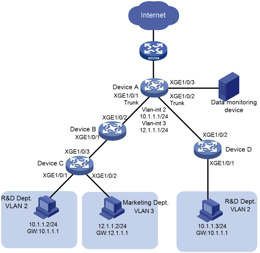
Network configuration
As shown in Figure 3, configure Layer 2 remote port mirroring to monitor the outgoing traffic from the Technical department.
Figure 5 Network diagram
Analysis
To ensure correct forwarding of mirrored packets, assign the ports that connect intermediate devices to the source and destination devices to the remote probe VLAN.
Restrictions and guidelines
When you configure devices for remote port mirroring, configure them in the order of the destination device, the intermediate devices, and the source device.
When you configure the monitor port for the remote destination group on the destination device, follow these restrictions and guidelines:
· Do not use a port of an existing mirroring group.
· Use the monitor port only for port mirroring.
· For the correct operation of port mirroring, disable the spanning tree feature on the monitor port if it is a Layer 2 interface.
· For the monitor port to forward mirrored packets to the data monitoring device without VLAN tags, assign the monitor port to the remote probe VLAN as an access port.
When you configure the remote probe VLAN on the source and destination devices, follow these restrictions and guidelines:
· Use an existing static VLAN that is not in use.
· Use the remote probe VLAN for port mirroring exclusively.
· The remote mirroring groups on the source device and destination device must use the same remote probe VLAN. Use this VLAN only for the same remote mirroring group on the source device and destination device.
When you configure a remote source group on the source device, follow these restrictions and guidelines:
· Do not assign source ports of the remote source group to the remote probe VLAN.
· To ensure the operation of mirroring, do not enable any of the following features on the egress port:
¡ Spanning tree.
¡ 802.1X.
¡ IGMP snooping.
¡ Static ARP.
¡ MAC address learning.
· A port of an existing mirroring group cannot be configured as an egress port.
· A mirroring group contains only one egress port.
· To implement Layer 2 remote mirroring when the source ports are Layer 3 interfaces, you must use the egress port method.
Procedures
Configuring Device A (the destination device)
# Create VLANs 2 and 3.
<DeviceA> system-view
[DeviceA] vlan 2 to 3
# Create VLAN-interface 2 and assign an IP address to it.
[DeviceA] interface Vlan-interface 2
[DeviceA-Vlan-interface2] ip address 10.1.1.1 24
[DeviceA-Vlan-interface2] quit
# Create VLAN-interface 3 and assign an IP address to it.
[DeviceA] interface Vlan-interface 3
[DeviceA-Vlan-interface3] ip address 12.1.1.1 24
[DeviceA-Vlan-interface3] quit
# Configure Ten-GigabitEthernet 1/0/1 as a trunk port, and assign the port to VLANs 2, 3, and 5.
<DeviceA> system-view
[DeviceA] interface ten-gigabitethernet 1/0/1
[DeviceA-Ten-GigabitEthernet1/0/1] port link-type trunk
[DeviceA-Ten-GigabitEthernet1/0/1] port trunk permit vlan 2 3 5
[DeviceA-Ten-GigabitEthernet1/0/1] quit
# Configure Ten-GigabitEthernet 1/0/2 as a trunk port, and assign the port to VLANs 2 and 5.
[DeviceA] interface ten-gigabitethernet 1/0/2
[DeviceA-Ten-GigabitEthernet1/0/2] port link-type trunk
[DeviceA-Ten-GigabitEthernet1/0/2] port trunk permit vlan 2 5
[DeviceA-Ten-GigabitEthernet1/0/2] quit
# Create a remote destination group.
[DeviceA] mirroring-group 1 remote-destination
# Create VLAN 5.
[DeviceA] vlan 5
[DeviceA-vlan5] quit
# Configure VLAN 5 as the remote probe VLAN of the remote destination group.
[DeviceA] mirroring-group 1 remote-probe vlan 5
# Configure Ten-GigabitEthernet 1/0/3 as the monitor port of the remote destination group.
[DeviceA] mirroring-group 1 monitor-port ten-gigabitethernet 1/0/3
# Configure Ten-GigabitEthernet 1/0/3 as an access port, and assign the port to the remote probe VLAN.
[DeviceA] interface ten-gigabitethernet 1/0/3
[DeviceA-Ten-GigabitEthernet1/0/3] port access vlan 5
# Disable the spanning tree feature on Ten-GigabitEthernet 1/0/3.
[DeviceA-Ten-GigabitEthernet1/0/3] undo stp enable
[DeviceA-Ten-GigabitEthernet1/0/3] quit
Configuring Device B (the intermediate device)
# Create VLANs 2 and 3.
<DeviceB> system-view
[DeviceB] vlan 2 to 3
# Create VLAN 5.
[DeviceB] vlan 5
[DeviceB-vlan5] quit
# Configure Ten-GigabitEthernet 1/0/1 as a trunk port, and assign the port to VLANs 2, 3, and 5.
[DeviceB] interface ten-gigabitethernet 1/0/1
[DeviceB-Ten-GigabitEthernet1/0/1] port link-type trunk
[DeviceB-Ten-GigabitEthernet1/0/1] port trunk permit vlan 2 3 5
[DeviceB-Ten-GigabitEthernet1/0/1] quit
# Configure Ten-GigabitEthernet 1/0/2 as a trunk port, and assign the port to VLANs 2, 3, and 5.
[DeviceB] interface ten-gigabitethernet 1/0/2
[DeviceB-Ten-GigabitEthernet1/0/2] port link-type trunk
[DeviceB-Ten-GigabitEthernet1/0/2] port trunk permit vlan 2 3 5
[DeviceB-Ten-GigabitEthernet1/0/2] quit
Configuring Device C (the source device)
# Create VLANs 2 and 3.
<DeviceC> system-view
[DeviceC] vlan 2 to 3
# Assign Ten-GigabitEthernet 1/0/1 to VLAN 2.
[DeviceC] interface ten-gigabitethernet 1/0/1
[DeviceC-Ten-GigabitEthernet1/0/1] port access vlan 2
[DeviceC-Ten-GigabitEthernet1/0/1] quit
# Assign Ten-GigabitEthernet 1/0/2 to VLAN 3.
[DeviceC] interface ten-gigabitethernet 1/0/2
[DeviceC-Ten-GigabitEthernet1/0/2] port access vlan 3
[DeviceC-Ten-GigabitEthernet1/0/2] quit
# Create a remote source group.
[DeviceC] mirroring-group 1 remote-source
# Create VLAN 5.
[DeviceC] vlan 5
[DeviceC-vlan5] quit
# Configure VLAN 5 as the remote probe VLAN for the remote source group.
[DeviceC] mirroring-group 1 remote-probe vlan 5
# Configure Ten-GigabitEthernet 1/0/1 as the source port of the remote source group and the mirroring direction as inbound.
[DeviceC] mirroring-group 1 mirroring-port ten-gigabitethernet 1/0/1 inbound
# Configure Ten-GigabitEthernet 1/0/3 as the egress port of the remote source group.
[DeviceC] mirroring-group 1 monitor-egress ten-gigabitethernet 1/0/3
# Configure Ten-GigabitEthernet 1/0/3 as a trunk port, and assign the port to VLANs 2, 3, and 5.
[DeviceC] interface ten-gigabitethernet 1/0/3
[DeviceC-Ten-GigabitEthernet1/0/3] port link-type trunk
[DeviceC-Ten-GigabitEthernet1/0/3] port trunk permit vlan 2 3 5
[DeviceC-Ten-GigabitEthernet1/0/3] quit
# Disable the spanning tree feature and MAC address learning on the egress port Ten-GigabitEthernet 1/0/3.
[DeviceC-Ten-GigabitEthernet1/0/3] undo stp enable
[DeviceC-Ten-GigabitEthernet1/0/3] undo mac-address mac-learning enable
[DeviceC-Ten-GigabitEthernet1/0/3] quit
Configuring Device D (the source device)
# Create VLAN 2.
<DeviceD> system-view
[DeviceD] vlan 2
[DeviceD-vlan2] quit
# Assign Ten-GigabitEthernet 1/0/1 to VLAN 2.
[DeviceD] interface ten-gigabitethernet 1/0/1
[DeviceD-Ten-GigabitEthernet1/0/1] port access vlan 2
[DeviceD-Ten-GigabitEthernet1/0/1] quit
# # Create remote source group 1.
[DeviceD] mirroring-group 1 remote-source
# Create VLAN 5.
[DeviceD] vlan 5
[DeviceD-vlan5] quit
# Configure VLAN 5 as the remote probe VLAN for the remote source group.
[DeviceD] mirroring-group 1 remote-probe vlan 5
# Configure Ten-GigabitEthernet 1/0/1 as the source port of the remote source group and the mirroring direction as inbound.
[DeviceD] mirroring-group 1 mirroring-port ten-gigabitethernet 1/0/1 inbound
# Configure Ten-GigabitEthernet 1/0/2 as the egress port of the remote source group.
[DeviceD] mirroring-group 1 monitor-egress ten-gigabitethernet 1/0/2
# Configure Ten-GigabitEthernet 1/0/2 as a trunk port, and assign the port to VLANs 2 and 5.
[DeviceD] interface ten-gigabitethernet 1/0/2
[DeviceD-Ten-GigabitEthernet1/0/2] port link-type trunk
[DeviceD-Ten-GigabitEthernet1/0/2] port trunk permit vlan 2 5
# Disable the spanning tree feature and MAC address learning on the egress port Ten-GigabitEthernet 1/0/2.
[DeviceD-Ten-GigabitEthernet1/0/2] undo stp enable
[DeviceD-Ten-GigabitEthernet1/0/2] undo mac-address mac-learning enable
[DeviceD-Ten-GigabitEthernet1/0/2] quit
Verifying the configuration
1. Verify mirroring group configurations on devices:
# Display information about mirroring group 1 on Device C.
[DeviceC] display mirroring-group 1
Mirroring group 1:
Type: Remote source
Status: Active
Mirroring port:
Ten-GigabitEthernet1/0/1 Inbound
Monitor egress port: Ten-GigabitEthernet1/0/3
Remote probe VLAN: 5
# Display information about mirroring group 1 on Device A.
[DeviceA] display mirroring-group 1
Mirroring group 1:
Type: Remote destination
Status: Active
Monitor port: Ten-GigabitEthernet1/0/3
Remote probe VLAN: 5
2. Use Wireshark for packet analysis:
# Ping a Marketing department host (12.1.1.2) from a Technical department host (10.1.1.2). (Details not shown.)
# Use Wireshark on the data monitoring device to capture the ping packets.
Figure 6 Ping packet analysis in Wireshark

The analysis shows that the data monitoring device can monitor the outgoing traffic from the Technical department.
Configuration files
· Device A:
#
mirroring-group 1 remote-destination
mirroring-group 1 remote-probe vlan 5
#
vlan 2 to 3
#
vlan 5
#
interface Vlan-interface2
ip address 10.1.1.1 255.255.255.0
#
interface Vlan-interface3
ip address 12.1.1.1 255.255.255.0
#
interface Ten-GigabitEthernet1/0/1
port link-mode bridge
port link-type trunk
port trunk permit vlan 1 to 3 5
#
interface Ten-GigabitEthernet1/0/2
port link-mode bridge
port link-type trunk
port trunk permit vlan 1 to 2 5
#
interface Ten-GigabitEthernet1/0/3
port link-mode bridge
port access vlan 5
undo stp enable
mirroring-group 1 monitor-port
#
· Device B:
#
vlan 2 to 3
#
vlan 5
#
interface Ten-GigabitEthernet1/0/1
port link-mode bridge
port link-type trunk
port trunk permit vlan 1 to 3 5
#
interface Ten-GigabitEthernet1/0/2
port link-mode bridge
port link-type trunk
port trunk permit vlan 1 to 3 5
#
· Device C:
#
mirroring-group 1 remote-source
mirroring-group 1 remote-probe vlan 5
#
vlan 2 to 3
#
vlan 5
#
interface Ten-GigabitEthernet1/0/1
port link-mode bridge
port access vlan 2
mirroring-group 1 mirroring-port inbound
#
interface Ten-GigabitEthernet1/0/2
port link-mode bridge
port access vlan 3
#
interface Ten-GigabitEthernet1/0/3
port link-mode bridge
port link-type trunk
port trunk permit vlan 1 to 3 5
mirroring-group 1 monitor-egress
#
interface Ten-GigabitEthernet1/0/5
port link-mode bridge
mirroring-group 1 reflector-port
#
· Device D:
#
mirroring-group 1 remote-source
mirroring-group 1 remote-probe vlan 5
#
vlan 2
#
vlan 5
#
interface Ten-GigabitEthernet1/0/1
port link-mode bridge
port access vlan 2
mirroring-group 1 mirroring-port inbound
#
interface Ten-GigabitEthernet1/0/2
port link-mode bridge
port link-type trunk
port trunk permit vlan 1 to 2 5
mirroring-group 1 monitor-egress
#
Example: Configuring local flow mirroring
Network configuration
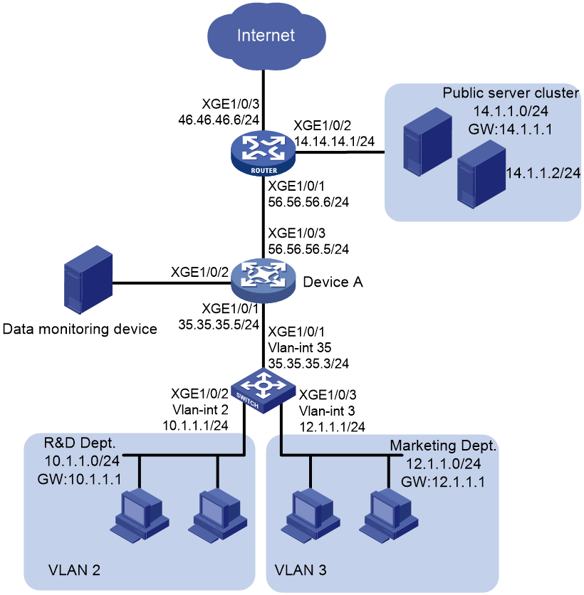
As shown in Figure 7, configure local flow mirroring to mirror the following traffic:
· HTTP traffic from the Technical department.
· Packets that the Marketing department hosts receive from the public server cluster during non-working hours from 18:00 to 08:30 (the next day) on working days.
Analysis
To configure local flow mirroring, you must perform the following tasks on Device A:
· Define traffic classes and configure match criteria to classify packets to be mirrored.
· Configure traffic behaviors to mirror the matching packets to the port that connects to the data monitoring device.
Procedures
1. Assign IP addresses to interfaces on Device A:
# Assign IP address 35.35.35.5 to Ten-GigabitEthernet 1/0/1.
<DeviceA> system-view
[DeviceA] interface ten-gigabitethernet 1/0/1
[DeviceA-Ten-GigabitEthernet1/0/1] port link-mode route
[DeviceA-Ten-GigabitEthernet1/0/1] ip address 35.35.35.5 24
[DeviceA-Ten-GigabitEthernet1/0/1] quit
# Assign IP addresses to Ten-GigabitEthernet 1/0/2 and Ten-GigabitEthernet 1/0/3 in the same way 35.35.35.5 is assigned to Ten-GigabitEthernet 1/0/1. (Details not shown.)
2. Configure a QoS policy to mirror HTTP traffic from the Technical department:
# Create ACL 3000 and configure a rule to match packets from the Technical department to the Internet.
[DeviceA] acl advanced 3000
[DeviceA-acl-ipv4-adv-3000] rule permit tcp destination-port eq 80 source 10.1.1.0 0.0.0.255
[DeviceA-acl-ipv4-adv-3000] quit
# Create traffic class classifier_research, and configure the match criterion as ACL 3000.
[DeviceA] traffic classifier classifier_research
[DeviceA-classifier-classifier_research] if-match acl 3000
[DeviceA-classifier-classifier_research] quit
# Create traffic behavior behavior_research, and configure the action of mirroring traffic to Ten-GigabitEthernet 1/0/2.
[DeviceA] traffic behavior behavior_research
[DeviceA-behavior-behavior_market] mirror-to interface ten-gigabitethernet 1/0/2
[DeviceA-behavior-behavior_research] quit
# Create QoS policy policy_research, and associate traffic class classifier_research with traffic behavior behavior_research in the QoS policy.
[DeviceA] qos policy policy_research
[DeviceA-qospolicy-policy_research] classifier classifier_research behavior behavior_research
[DeviceA-qospolicy-policy_research] quit
3. Configure a QoS policy to mirror traffic that the Marketing department hosts receive from the public server cluster:
# Create a periodic time range off-work1, setting it to be active between 0:00 and 8:30 during working days.
[DeviceA] time-range off-work1 0:00 to 8:30 working-day
# Create a periodic time range off-work2, setting it to be active between 18:00 and 24:00 during working days.
[DeviceA] time-range off-work2 18:00 to 24:00 working-day
# Create ACL 3001, and configure two rules to match packets from the public server cluster to the Marketing department hosts in non-working hours on working days.
[DeviceA] acl advanced 3001
[DeviceA-acl-ipv4-adv-3001] rule permit ip destination 12.1.1.0 0.0.0.255 source 14.1.1.0 0.0.0.255 time-range off-work1
[DeviceA-acl-ipv4-adv-3001] rule permit ip destination 12.1.1.0 0.0.0.255 source 14.1.1.0 0.0.0.255 time-range off-work2
[DeviceA-acl-ipv4-adv-3001] quit
# Create traffic class classifier_market, and configure the match criterion as ACL 3001.
[DeviceA] traffic classifier classifier_market
[DeviceA-classifier-classifier_market] if-match acl 3001
[DeviceA-classifier-classifier_market] quit
# Create traffic behavior behavior_market, and configure the action of mirroring traffic to Ten-GigabitEthernet 1/0/2.
[DeviceA] traffic behavior behavior_market
[DeviceA-behavior-behavior_market] mirror-to interface ten-gigabitethernet 1/0/2
[DeviceA-behavior-behavior_market] quit
# Create QoS policy policy_market, and associate traffic class classifier_market with traffic behavior behavior_market in the QoS policy.
[DeviceA] qos policy policy_market
[DeviceA-qospolicy-policy_market] classifier classifier_market behavior behavior_market
[DeviceA-qospolicy-policy_market] quit
4. Apply the QoS policies:
# Apply QoS policy policy_research to the inbound direction of Ten-GigabitEthernet 1/0/1.
[DeviceA] interface ten-gigabitethernet 1/0/1
[DeviceA-Ten-GigabitEthernet1/0/1] port link-mode route
[DeviceA-Ten-GigabitEthernet1/0/1] qos apply policy policy_research inbound
[DeviceA-Ten-GigabitEthernet1/0/1] quit
# Apply QoS policy policy_market to the inbound direction of Ten-GigabitEthernet 1/0/3.
[DeviceA] interface ten-gigabitethernet 1/0/3
[DeviceA-Ten-GigabitEthernet1/0/3] port link-mode route
[DeviceA-Ten-GigabitEthernet1/0/3] qos apply policy policy_market inbound
[DeviceA-Ten-GigabitEthernet1/0/3] quit
Verifying the configuration
1. Display local flow mirroring information on Device A.
[DeviceA] display qos policy interface
Interface: Ten-GigabitEthernet1/0/1
Direction: Inbound
Policy: policy_research
Classifier: classifier_research
Operator: AND
Rule(s) :
If-match acl 3000
Behavior: behavior_research
Mirroring:
Mirror to the interface: Ten-GigabitEthernet1/0/2
Interface: Ten-GigabitEthernet1/0/3
Direction: Inbound
Policy: policy_market
Classifier: classifier_market
Operator: AND
Rule(s) :
If-match acl 3001
Behavior: behavior_market
Mirroring:
Mirror to the interface: Ten-GigabitEthernet1/0/2
2. Use Wireshark for packet analysis:
# Use a Technical department host (10.1.1.2) to access the IP address 46.46.46.4 and port 80 through Telnet. (Details not shown.)
# Use Wireshark on the data monitoring device to capture the packets.
Figure 8 HTTP traffic analysis in Wireshark
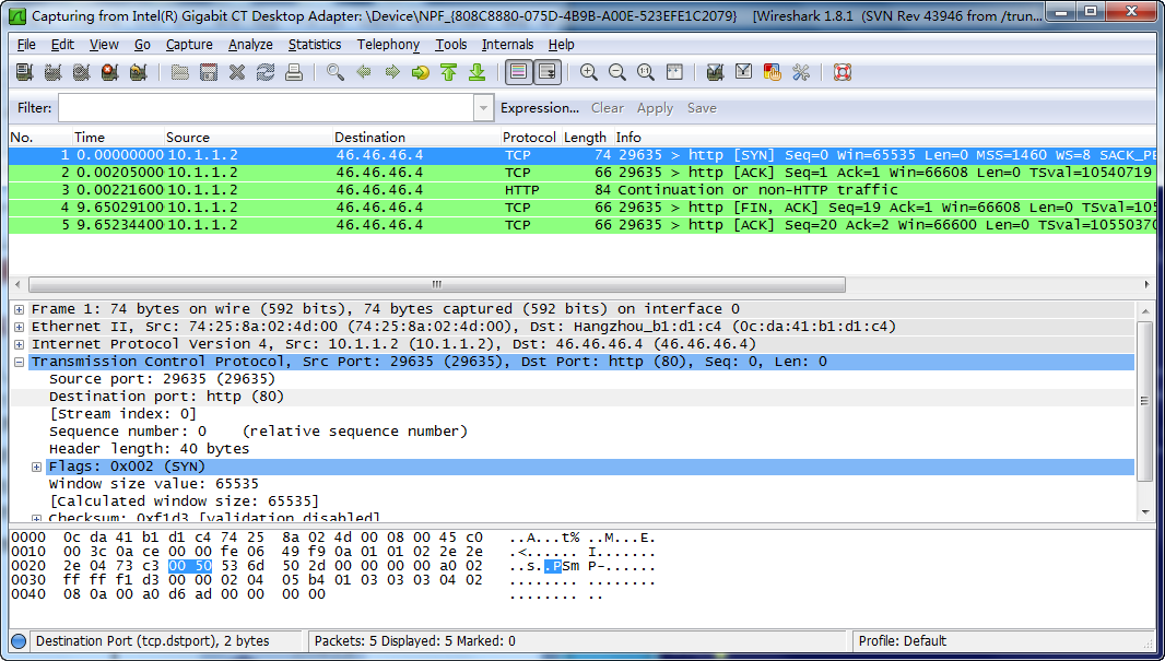
The analysis shows that the data monitoring device can monitor the HTTP traffic from the Technical department.
# On a non-working hour of a working day, ping a public server (14.1.1.2) from a Marketing department host (12.1.1.2). (Details not shown.)
# Use Wireshark on the data monitoring device to capture the ping packets.
Figure 9 Ping packet analysis in Wireshark
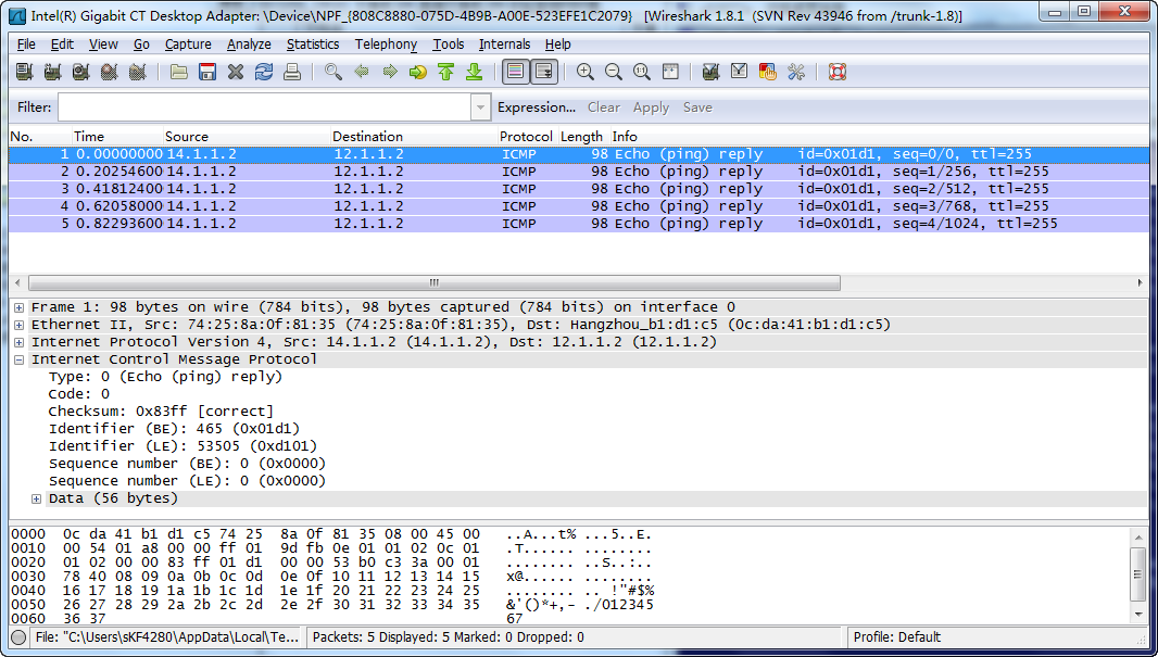
The analysis shows that the data monitoring device can monitor the traffic that the public server cluster send to the Marketing department during non-working hours on working days.
Configuration files
#
time-range off-work1 00:00 to 08:30 working-day
time-range off-work2 18:00 to 24:00 working-day
#
acl advanced 3000
rule 0 permit tcp source 10.1.1.0 0.0.0.255 destination-port eq www
acl advanced 3001
rule 0 permit ip source 14.1.1.0 0.0.0.255 destination 12.1.1.0 0.0.0.255 time-range off-work1
rule 5 permit ip source 14.1.1.0 0.0.0.255 destination 12.1.1.0 0.0.0.255 time-range off-work2
#
traffic classifier classifier_research operator and
if-match acl 3000
traffic classifier classifier_market operator and
if-match acl 3001
#
traffic behavior behavior_research
mirror-to interface Ten-GigabitEthernet1/0/2
traffic behavior behavior_market
mirror-to interface Ten-GigabitEthernet1/0/2
#
qos policy policy_research
classifier classifier_research behavior behavior_research
qos policy policy_market
classifier classifier_market behavior behavior_market
#
interface Ten-GigabitEthernet1/0/1
port link-mode route
ip address 35.35.35.5 255.255.255.0
qos apply policy policy_research inbound
#
interface Ten-GigabitEthernet1/0/3
port link-mode route
ip address 56.56.56.5 255.255.255.0
qos apply policy policy_market inbound
#
Example: Configuring flow mirroring in a flexible way
Network configuration
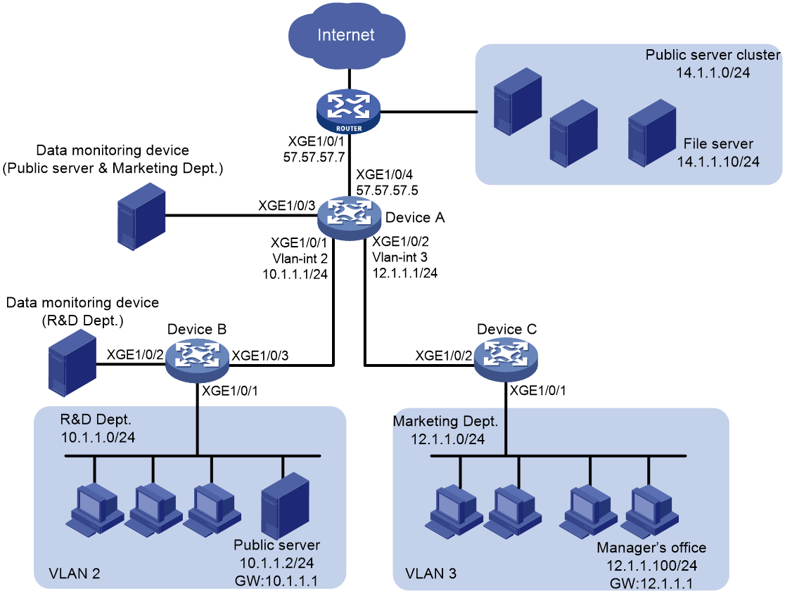
As shown in Figure 10, configure flow mirroring to monitor the network traffic by using the data monitoring devices as follows:
· On the data monitoring device connected to Device A:
¡ Monitor the traffic from public servers.
¡ Monitor the traffic from the file server only in the non-working hours (18:00 to 8:30 of the next day) on working days.
¡ Monitor the traffic from the Marketing department to the Internet, except the traffic from the Marketing department manager office to the Internet.
· On the data monitoring device connected to Device B:
¡ Monitor the traffic from the Technical department hosts and the server for external access.
¡ Monitor the outgoing traffic from the server in non-working hours (18:00 to 8:30 of the next day) on working days.
Analysis
To filter data from a specific source, use one of the following methods:
· Apply a QoS policy of denying traffic to the outgoing interface of the mirrored data. The data from the specified source is not received by the data monitoring device.
· Configure a class-behavior association to permit the data from the specified source, and then issue the class-behavior association before the class-behavior association for mirroring. Data from the specified source is not mirrored.
· Use the packet-filter command on the outgoing interface of the mirrored data. The data from the specified source is not received by the data monitoring device.
Procedures
Configuring Device A to mirror traffic from the public servers
1. Configure a QoS policy to mirror traffic from all public servers:
# Create ACL 2000 to match packets from subnet 14.1.1.0/24.
<DeviceA> system-view
[DeviceA] acl basic 2000
[DeviceA-acl-ipv4-basic-2000] rule permit source 14.1.1.0 0.0.0.255
[DeviceA-acl-ipv4-basic-2000] quit
# Create traffic class classifier_servers, and configure the match criterion as ACL 2000.
[DeviceA] traffic classifier classifier_servers
[DeviceA-classifier-classifier_servers] if-match acl 2000
[DeviceA-classifier-classifier_servers] quit
# Create traffic behavior behavior_servers, and configure the action of mirroring traffic to Ten-GigabitEthernet 1/0/3.
[DeviceA] traffic behavior behavior_servers
[DeviceA-behavior-behavior_servers] mirror-to interface ten-gigabitethernet 1/0/3
[DeviceA-behavior-behavior_servers] quit
# Create QoS policy policy_servers, and associate traffic class classifier_servers with traffic behavior behavior_servers in the QoS policy.
[DeviceA] qos policy policy_servers
[DeviceA-qospolicy-policy_servers] classifier classifier_servers behavior behavior_servers
[DeviceA-qospolicy-policy_servers] quit
# Apply QoS policy policy_servers to the inbound direction of Ten-GigabitEthernet 1/0/4.
[DeviceA] interface ten-gigabitethernet 1/0/4
[DeviceA-Ten-GigabitEthernet1/0/4] port link-mode route
[DeviceA-Ten-GigabitEthernet1/0/4] qos apply policy policy_servers inbound
[DeviceA-Ten-GigabitEthernet1/0/4] quit
2. Configure a QoS policy to filter packets from the file server in working hours:
# Create a periodic time range work-time, setting it to be active between 8:30 and 18:00 during working days.
[DeviceA] time-range work-time 8:30 to 18:00 working-day
# Create ACL 2001, and configure a rule to match packets from 14.1.1.10 in working hours on working days.
[DeviceA] acl basic 2001
[DeviceA-acl-ipv4-basic-2001] rule permit source 14.1.1.10 0.0.0.0 time-range work-time
[DeviceA-acl-ipv4-basic-2001] quit
# Create traffic class classifier_fileserver, and configure the match criterion as ACL 2001.
[DeviceA] traffic classifier classifier_fileserver
[DeviceA-classifier-classifier_fileserver] if-match acl 2001
[DeviceA-classifier-classifier_fileserver] quit
# Create traffic behavior behavior_fileserver, and configure the action of denying traffic.
[DeviceA] traffic behavior behavior_fileserver
[DeviceA-behavior-behavior_fileserver] filter deny
[DeviceA-behavior-behavior_fileserver] quit
# Create QoS policy policy_fileserver, and associate traffic class classifier_fileserver with traffic behavior behavior_fileserver in the QoS policy.
[DeviceA] qos policy policy_fileserver
[DeviceA-qospolicy-policy_fileserver] classifier classifier_fileserver behavior behavior_fileserver
[DeviceA-qospolicy-policy_fileserver] quit
# Apply QoS policy policy_fileserver to the outbound direction of Ten-GigabitEthernet 1/0/3.
[DeviceA] interface ten-gigabitethernet 1/0/3
[DeviceA-Ten-GigabitEthernet1/0/3] qos apply policy policy_fileserver outbound
[DeviceA-Ten-GigabitEthernet1/0/3] quit
Configuring Device A to mirror the Internet traffic from the Marketing department
1. Create a traffic class and a traffic behavior for the packets:
# Create ACL 3000, and configure a rule to match packets from subnet 12.1.1.0/24.
[DeviceA] acl advanced 3000
[DeviceA-acl-ipv4-adv-3000] rule permit tcp destination-port eq 80 source 12.1.1.0 0.0.0.255
[DeviceA-acl-ipv4-adv-3000] quit
# Create traffic class classifier_market, and configure the match criterion as ACL 3000.
[DeviceA] traffic classifier classifier_market
[DeviceA-classifier-classifier_market] if-match acl 3000
[DeviceA-classifier-classifier_market] quit
# Create traffic behavior behavior_market, and configure the action of mirroring traffic to Ten-GigabitEthernet 1/0/3.
[DeviceA] traffic behavior behavior_market
[DeviceA-behavior-behavior_market] mirror-to interface ten-gigabitethernet 1/0/3
[DeviceA-behavior-behavior_market] quit
2. Create a traffic class and a traffic behavior for the packets from the manager office:
# Create ACL 3001, and configure a rule to match packets from 12.1.1.100.
[DeviceA] acl advanced 3001
[DeviceA-acl-ipv4-adv-3001] rule permit tcp destination-port eq 80 source 12.1.1.100 0.0.0.0
[DeviceA-acl-ipv4-adv-3001] quit
# Create traffic class classifier_market_mgr, and configure the match criterion as ACL 3001.
[DeviceA] traffic classifier classifier_market_mgr
[DeviceA-classifier-classifier_market_mgr] if-match acl 3001
[DeviceA-classifier-classifier_market_mgr] quit
# Create traffic behavior behavior_market_mgr, and configure the action of permitting traffic to pass through.
[DeviceA] traffic behavior behavior_market_mgr
[DeviceA-behavior-behavior_market_mgr] filter permit
[DeviceA-behavior-behavior_market_mgr] quit
3. Create a QoS policy and associate the traffic classes and traffic behaviors:
# Create QoS policy policy_market.
[DeviceA] qos policy policy_market
# Associate traffic class classifier_market_mgr with traffic behavior behavior_market_mgr in the QoS policy.
[DeviceA-qospolicy-policy_market] classifier classifier_market_mgr behavior behavior_market_mgr
# Associate traffic class classifier_market with traffic behavior behavior_market in the QoS policy.
[DeviceA-qospolicy-policy_market] classifier classifier_market behavior behavior_market
# Display the sequence of issuing the class–behavior associations.
[DeviceA-qospolicy-policy_market] display this
#
qos policy policy_market
classifier classifier_market_mgr behavior behavior_market_mgr
classifier classifier_market behavior behavior_market
#
return
[DeviceA-qospolicy-policy_market] quit
The output shows that the class–behavior association for the manager office are issued first. The packets from the manager office to access the Internet are not mirrored.
4. Apply QoS policy policy_market to the inbound direction of Ten-GigabitEthernet 1/0/2.
[DeviceA] interface ten-gigabitethernet 1/0/2
[DeviceA-Ten-GigabitEthernet1/0/2] qos apply policy policy_market inbound
[DeviceA-Ten-GigabitEthernet1/0/2] quit
Configuring Device B to mirror traffic from the Technical department
1. Configure local mirroring on Device B:
# Create local mirroring group 1.
<DeviceB> system-view
[DeviceB] mirroring-group 1 local
# Configure the mirroring group to monitor the incoming traffic of the port Ten-GigabitEthernet 1/0/1.
[DeviceB] mirroring-group 1 mirroring-port ten-gigabitethernet 1/0/1 inbound
# Configure Ten-GigabitEthernet 1/0/2 as the monitor port of the mirroring group.
[DeviceB] mirroring-group 1 monitor-port ten-gigabitethernet 1/0/2
2. Configure an ACL to filter the outgoing traffic from the server (10.1.1.2) in working hours:
# Create a periodic time range work-time, setting it to be active between 8:30 and 18:00 during working days.
[DeviceB] time-range work-time 8:30 to 18:00 working-day
# Create ACL 2000, and configure a rule to deny packets from 10.1.1.2 in working hours on working days.
[DeviceB] acl basic 2000
[DeviceB-acl-ipv4-basic-2000] rule deny source 10.1.1.2 0.0.0.0 time-range work-time
[DeviceB-acl-ipv4-basic-2000] quit
# Apply ACL 2000 to filter the outgoing traffic on Ten-GigabitEthernet 1/0/2.
[DeviceB] interface ten-gigabitethernet1/0/2
[DeviceB-Ten-GigabitEthernet1/0/2] packet-filter 2000 outbound
[DeviceB-Ten-GigabitEthernet1/0/2] quit
Verifying the configuration
1. Verify flow mirroring configurations on devices:
# Display flow mirroring information on Device A.
[DeviceA] display qos policy interface
Interface: Ten-GigabitEthernet1/0/2
Direction: Inbound
Policy: policy_market
Classifier: classifier_market_mgr
Operator: AND
Rule(s) : If-match acl 3001
Behavior: behavior_market_mgr
Filter enable: Permit
Classifier: classifier_market
Operator: AND
Rule(s) : If-match acl 3000
Behavior: behavior_market
Mirroring:
Mirror to the interface: Ten-GigabitEthernet1/0/3
Interface: Ten-GigabitEthernet1/0/3
Direction: Outbound
Policy: policy_fileserver
Classifier: classifier_fileserver
Operator: AND
Rule(s) : If-match acl 2001
Behavior: behavior_fileserver
Mirroring:
Mirror to the interface: Ten-GigabitEthernet1/0/3
Interface: Ten-GigabitEthernet1/0/4
Direction: Inbound
Policy: policy_servers
Classifier: classifier_servers
Operator: AND
Rule(s) : If-match acl 2000
Behavior: behavior_servers
Mirroring:
Mirror to the interface: Ten-GigabitEthernet1/0/3
# Display information about mirroring group 1 on Device B.
[DeviceB] display mirroring-group 1
Mirroring group 1:
Type: Local
Status: Active
Mirroring port:
Ten-GigabitEthernet1/0/1 Inbound
Monitor port: Ten-GigabitEthernet1/0/2
2. Use Wireshark for packet analysis:
# Use a Marketing department host (12.1.1.2) and the manager's host (12.1.1.100) to access the IP address 57.57.57.7 and port 80 through Telnet. (Details not shown.)
# Use Wireshark on the data monitoring device connected to Device A to capture the packets.
Figure 11 HTTP traffic analysis in Wireshark
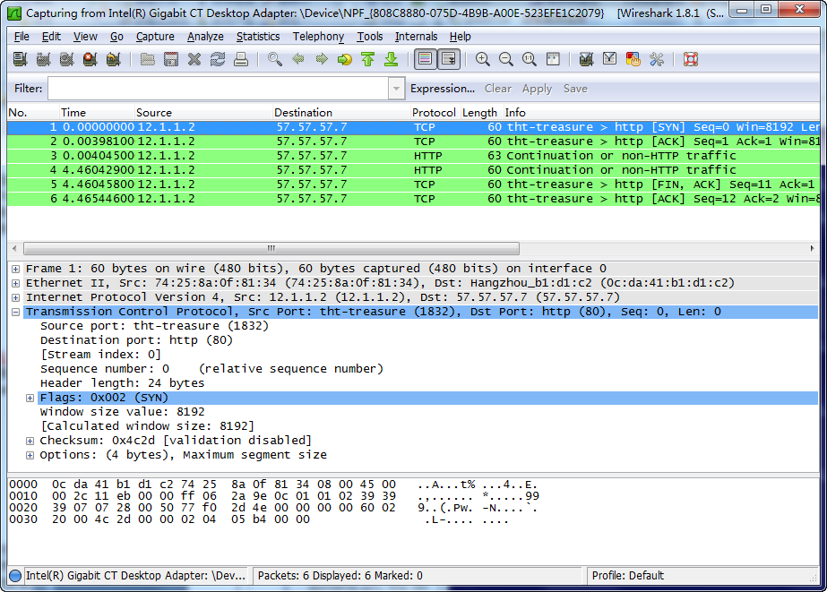
The analysis shows that the data monitoring device monitors the traffic only from the Marketing department host (12.1.1.2). The traffic from the manager office is not monitored.
Configuration files
· Device A:
#
time-range work-time 08:30 to 18:00 working-day
#
acl basic 2000
rule 0 permit source 14.1.1.0 0.0.0.255
acl basic 2001
rule 0 permit source 14.1.1.10 0 time-range work-time
#
acl advanced 3000
rule 0 permit tcp source 12.1.1.0 0.0.0.255 destination-port eq www
acl advanced 3001
rule 0 permit tcp source 12.1.1.100 0 destination-port eq www
#
traffic classifier classifier_servers operator and
if-match acl 2000
traffic classifier classifier_fileserver operator and
if-match acl 2001
traffic classifier classifier_market operator and
if-match acl 3000
traffic classifier classifier_market_mgr operator and
if-match acl 3001
#
traffic behavior behavior_servers
mirror-to interface Ten-GigabitEthernet1/0/3
traffic behavior behavior_fileserver
filter deny
traffic behavior behavior_market
mirror-to interface Ten-GigabitEthernet1/0/3
traffic behavior behavior_market_mgr
filter permit
#
qos policy policy_fileserver
classifier classifier_fileserver behavior behavior_fileserver
qos policy policy_market
classifier classifier_market_mgr behavior behavior_market_mgr
classifier classifier_market behavior behavior_market
qos policy policy_servers
classifier classifier_servers behavior behavior_servers
#
interface Ten-GigabitEthernet1/0/1
port link-mode bridge
port link-type trunk
port trunk permit vlan 1 to 2
#
interface Ten-GigabitEthernet1/0/2
port link-mode bridge
port link-type trunk
port trunk permit vlan 1 3
qos apply policy policy_market inbound
#
interface Ten-GigabitEthernet1/0/3
port link-mode bridge
qos apply policy policy_fileserver outbound
#
interface Ten-GigabitEthernet1/0/4
port link-mode route
ip address 57.57.57.5 255.255.255.0
qos apply policy policy_servers inbound
#
· Device B:
#
mirroring-group 1 local
#
time-range work-time 08:30 to 18:00 working-day
#
acl basic 2000
rule 0 deny source 10.1.1.2 0 time-range work-time
#
interface Ten-GigabitEthernet1/0/1
port link-mode bridge
port access vlan 2
mirroring-group 1 mirroring-port inbound
#
interface Ten-GigabitEthernet1/0/2
port link-mode bridge
packet-filter 2000 outbound
mirroring-group 1 monitor-port
#
Related documentation
· H3C S10500X Switch Series Network Management and Monitoring Configuration Guide-R759X
· H3C S10500X Switch Series Network Management and Monitoring Command Reference-R759X