- Table of Contents
- Related Documents
-
| Title | Size | Download |
|---|---|---|
| 01-Text | 128.04 KB |
Contents
1 About the H3C DP52-52 power adapter
2 Safety guidelines and warnings
3 Installing the power adapter
Examining the installation environment
1 About the H3C DP52-52 power adapter
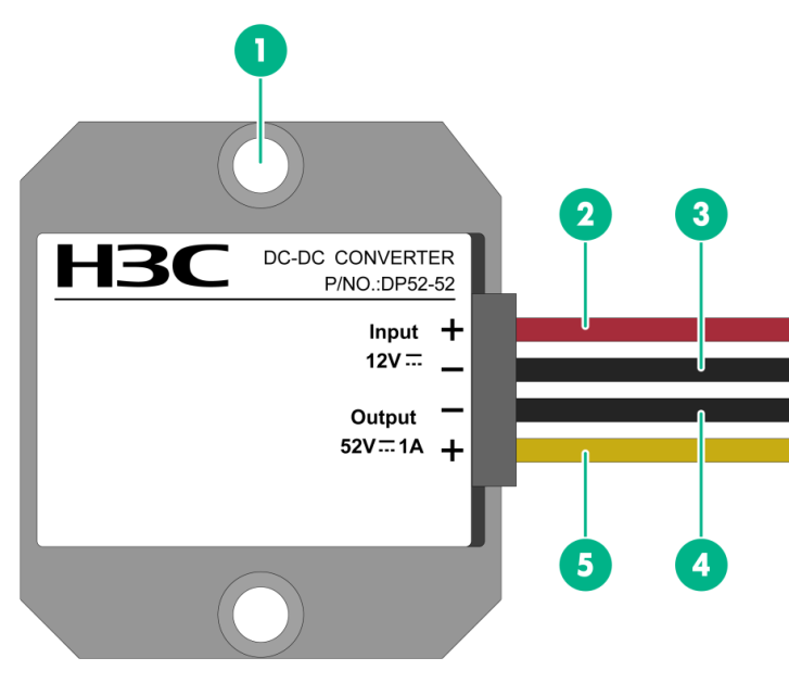
Device view
Figure1-1 View
|
(1) Screw hole |
(2) Positive DC input wire |
|
(3) Negative DC input wire |
(4) Negative DC output wire |
|
(5) Positive DC output wire |
|
Technical specifications
Table1-1 Technical specifications
|
Item |
Specifications |
|
Dimensions (H × W × D) |
57 × 64 × 22 mm (2.24 × 2.52 × 0.87 in) |
|
Net weight |
300 g (10.58 oz) |
|
Input voltage range |
11 VDC to 15 VDC |
|
Rated input voltage |
12 VDC |
|
Rated output voltage |
52 VDC |
|
Output voltage range |
50.44 VDC to 53.56 VDC |
|
Rated output current |
1.0 A |
|
Rated output power |
52 W |
|
Protection rating |
IP68 |
2 Safety guidelines and warnings
To avoid possible device damage or bodily injury, read the following safety guidelines and warnings carefully before using the power adapter.
Safety guidelines
· Keep good ventilation and heat dissipation during the operating process of the power adapter to ensure long-term reliability.
· Use the power adapter in an environment that meets the specified requirements in Table3-1.
· The potentiometer in the power adapter can be adjusted only by qualified personnel as required and they must be aware of the impact of the adjustment.
· Do not operate the power adapter in an environment with volatile gases or flammable materials.
· Do not remove the cover from the power adapter. Do not touch, repair, or replace the components inside the power adapter.
· Cut off power immediately if smoke or unpleasant smell is emitted during the startup or operating process of the power adapter.
Safety warnings
· Once the power adapter enters the protection mode, stop the power adapter immediately and handle the power adapter according to the relevant maintenance guidelines.
· Only qualified personnel can connect the power adapter to a power source equipment.
· Power might be still present on the adapter after it is just shut down. Shut down the adapter and wait for five minutes before working on the power adapter.
· Pay attention to the safety signs. To avoid electric shocks and burns, do not touch the location with your hands directly where there are safety warning signs and high-voltage signs.
3 Installing the power adapter
Examining the installation environment
Table3-1 Requirements for the installation environment
|
Item |
Specifications |
|
Operating temperature |
–30°C to +60°C (–22°F to +140°F) |
|
Storage temperature |
–40°C to +85°C (–40°F to +185°F) |
|
Relative humidity (noncondensing) |
5% to 95% |
|
Altitude |
≤ 5000 m (16404.20 ft) The operating temperature decreases by 1°C (33.8°F) for every increase of 200 m (656.17 ft) above 3000 m (9842.52 ft) in altitude. |
|
Cooling method |
Natural cooling |
Installing the power adapter
The following installs the power adapter on a DIN rail:
1. Wear an ESD wrist strap and make sure the wrist strap has good skin contact and is reliably grounded.
2. Determine the power adapter installation position on the DIN rail according to the location of power source equipment and the input and output cable lengths of the power adapter.
3. Thread two cable ties through the power adapter screw holes and through the DIN rail installation holes, and fasten the cable tie to secure the power adapter to the DIN rail.
4 Connecting the power wires
|
|
CAUTION: · To protect the power adapter from damages caused by incorrect power cord connections, identify the input, output, positive (+), and negative (-) marks on the power adapter before connecting the power wires. · Before connecting the power wires, turn off the circuit breaker at the power input end. You can use a 10 A circuit breaker. |
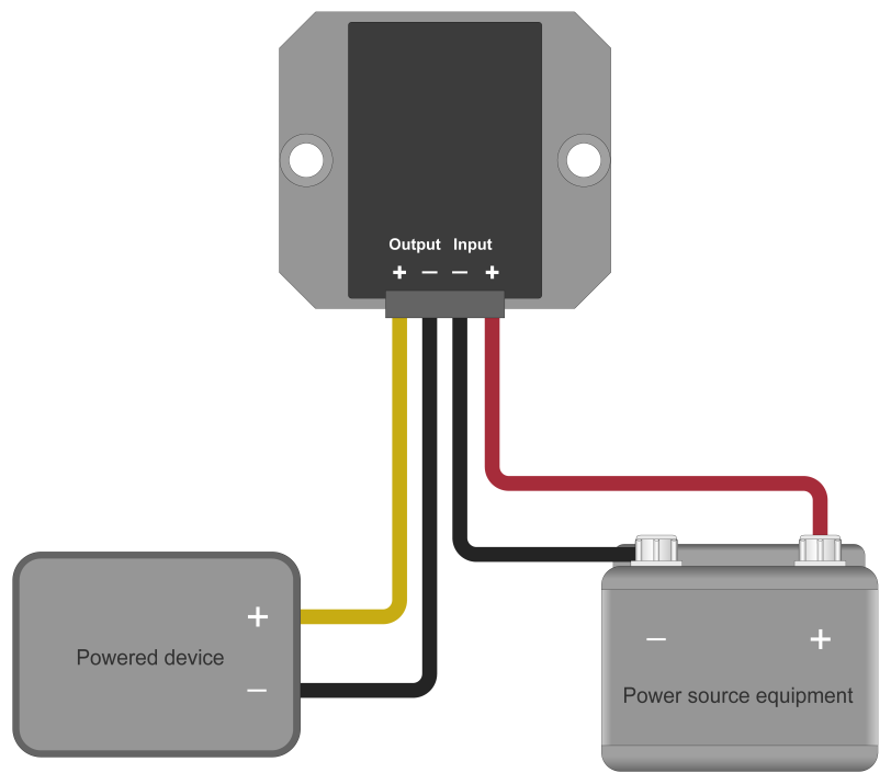
The DC power source equipment in Figure4-2 is for illustration only. Prepare a DC power source equipment that meets the voltage requirements yourself.
To connect the power wires:
1. Wear an ESD wrist strap and make sure the wrist strap has good skin contact and is reliably grounded.
2. Connect the positive (yellow) and negative (black) DC output wires of the adapter to the positive and negative input terminals of the device to which the adapter will supply power, respectively. Then fasten the wires.
3. Connect the positive (red) and negative (black) DC input wires of the adapter to the positive and negative poles of the power source equipment, respectively. Then fasten the wires.
4. Verify that the power wires are connected correctly and then turn on the circuit breaker at the power input end.
Figure4-2 Connecting the power wires