- Table of Contents
- Related Documents
-
| Title | Size | Download |
|---|---|---|
| 02-Ethernet interface configuration | 141.70 KB |
Contents
Configuring Ethernet interfaces
Configuring a management Ethernet interface
Ethernet interface naming conventions
Configuring common Ethernet interface settings
Configuring the physical type for a combo interface (single combo interface)
Configuring the operating mode for a 10-GE interface
Setting the J0 and J1 overhead bytes for a 10-GE interface
Configuring basic settings of an Ethernet interface
Configuring basic settings of an Ethernet subinterface
Configuring the link mode of an Ethernet interface
Configuring jumbo frame support
Configuring physical state change suppression on an Ethernet interface
Configuring dampening on an Ethernet interface
Configuring generic flow control on an Ethernet interface
Setting the statistics polling interval
Enabling subinterface rate statistics collection on an Ethernet interface
Enabling loopback testing on an Ethernet interface
Restoring the default settings for an interface
Configuring a Layer 3 Ethernet interface or subinterface
Setting the MTU for an Ethernet interface or subinterface
Enabling statistics collection on a Layer 3 Ethernet subinterface
Display and maintenance commands
Configuring Ethernet interfaces
About Ethernet interface
The device supports Ethernet interfaces, management Ethernet interfaces, Console interfaces, and USB interfaces. For the interface types and the number of interfaces supported by a device model, see the installation guide.
This chapter describes how to configure management Ethernet interfaces and Ethernet interfaces.
Configuring a management Ethernet interface
About this task
A management interface uses an RJ-45/LC connector. You can connect the interface to a PC for software loading and system debugging, or connect it to a remote NMS for remote system management.
(In standalone mode.)
Each MPU on a device has a management Ethernet interface. For management link backup, perform the following tasks:
1. Connect your PC to the management Ethernet interface on the active MPU.
2. Connect the PC to a management Ethernet interface with the same interface number on a standby MPU.
The two management Ethernet interfaces operate as follows:
· When the device has multiple management Ethernet interfaces, only the management Ethernet interface on the active MPU processes management traffic.
· When the management Ethernet interface on the active MPU fails, the management Ethernet interface on the standby MPU takes over to process management traffic.
· When the management Ethernet interface on the active MPU recovers, it takes over to process management traffic again.
(In IRF mode.)
Each MPU in an IRF system has a management Ethernet interface. For management link backup, perform the following tasks:
1. Connect your PC to the management Ethernet interface on the global active MPU.
2. Connect the PC to a management Ethernet interface with the same interface number on a global standby MPU.
The two management Ethernet interfaces operate as follows:
· When the IRF system has multiple management Ethernet interfaces, only the management Ethernet interface on the global active MPU processes management traffic.
· When the management Ethernet interface on the global active MPU fails, the management Ethernet interface on the global standby MPU takes over to process management traffic.
· When the management Ethernet interface on the global active MPU recovers, it takes over to process management traffic again.
Procedure
1. Enter system view.
system-view
2. Enter management Ethernet interface view.
interface M-GigabitEthernet interface-number
3. (Optional.) Set the interface description.
description text
The default setting is M-GigabitEthernet0/0/0 Interface.
4. (Optional.) Set the duplex mode for the management Ethernet interface.
duplex { auto | full | half }
By default, the duplex mode is auto for a management Ethernet interface.
5. (Optional.)_Set the speed for the management Ethernet interface.
speed { 10 | 100 | 1000 | auto }
By default, the speed is auto for a management Ethernet interface.
6. (Optional.) Shut down the interface.
shutdown
By default, the management Ethernet interface is up.
Ethernet interface naming conventions
In standalone mode, the Ethernet interfaces are named in the format of interface type A/B/C. The letters that follow the interface type represent the following elements:
· A—Card slot number.
· B—Interface module slot number. If the card has no interface module, this value is fixed at 0.
· C—Port index.
In IRF mode, the Ethernet interfaces are named in the format of interface type A/B/C/D. The letters that follow the interface type represent the following elements:
· A—IRF member ID, which can be 1 or 2.
· B—Card slot number.
· C—Interface module slot number. If the card has no interface module, this value is fixed at 0.
· D—Port index.
Configuring common Ethernet interface settings
Configuring the physical type for a combo interface (single combo interface)
About this task
A combo interface is a logical interface that physically comprises one fiber combo port and one copper combo port. The two ports share one forwarding channel and one interface view. As a result, they cannot work simultaneously. When you activate one port, the other port is automatically disabled. In the interface view, you can activate the fiber or copper combo port, and configure other port attributes such as the interface rate and duplex mode.
Prerequisites
Before you configure combo interfaces, complete the following tasks:
· Determine the combo interfaces on your device. Identify the two physical interfaces that belong to each combo interface according to the marks on the device panel.
· Use the display interface command to determine which port (fiber or copper) of each combo interface is active:
¡ If the copper port is active, the output includes "Media type is twisted pair, Port hardware type is 1000_BASE_T."
¡ If the fiber port is active, the output does not include this information.
Also, you can use the display this command in the view of each combo interface to display the combo interface configuration:
¡ If the fiber port is active, the combo enable fiber command exists in the output.
¡ If the copper port is active, the combo enable fiber command does not exist in the output.
Procedure
1. Enter system view.
system-view
2. Enter Ethernet interface view.
interface interface-type interface-number
3. Activate the copper combo port or fiber combo port.
combo enable { copper | fiber }
By default, the copper combo port is active.
Configuring the operating mode for a 10-GE interface
About this task
10-GE interfaces support the following operating modes:
· LAN mode—In LAN mode, a 10-GE interface transmits Ethernet packets and provides Ethernet network access.
· WAN mode—In WAN mode, a 10-GE interface transmits SDH frames and provides SDH network access. In this mode, a 10-GE interface supports only point-to-point connections.
Restrictions and guidelines
A 10-GE interface operating in WAN mode encapsulates Ethernet packets in SDH frames. A 10G POS interface encapsulates PPP packets in SDH frames. However, they cannot communicate with each other because they encapsulate different kinds of packets.
Procedure
1. Enter system view.
system-view
2. Enter 10-GE interface view.
interface ten-gigabitethernet interface-number
3. Configure the 10-GE interface to operate in LAN or WAN mode.
port-mode { lan | wan }
By default, a 10-GE interface operates in LAN mode.
Setting the J0 and J1 overhead bytes for a 10-GE interface
About this task
The overhead bytes in SDH frames provide the operation and maintenance features such as hierarchical management of the transmission network. J0 and J1 bytes provide internetworking support between devices of different countries, regions, or vendors.
The Regenerator Section Trace byte J0 is usually configured as a section access point identifier. The sending end keeps the connection with the receiving end by sending this byte repeatedly.
The Path Trace byte J1 is usually configured as a high-order path access point identifier. J1 also enables two ends to keep their connection.
To ensure smooth communication, make sure the sending and receiving ends have the same J0 and J1 bytes.
Procedure
1. Enter system view.
system-view
2. Enter 10-GE interface view.
interface ten-gigabitethernet interface-number
3. Configure the 10-GE interface to operate in WAN mode.
port-mode wan
By default, a 10-GE interface operates in LAN mode.
4. Set the J0 and J1 bytes.
flag { j0 | j1 } sdh flag-value
By default, the J0 and J1 bytes are padded with 0s.
Configuring basic settings of an Ethernet interface
About this task
You can configure an Ethernet interface to operate in one of the following duplex modes:
· Full-duplex mode—The interface can send and receive packets simultaneously.
· Half-duplex mode—The interface can only send or receive packets at a given time.
· Autonegotiation mode—The interface negotiates a duplex mode with its peer.
You can set the speed of an Ethernet interface or enable it to automatically negotiate a speed with its peer.
Restrictions and guidelines
The shutdown and loopback commands are mutually exclusive.
Procedure
1. Enter system view.
system-view
2. Enter Ethernet interface view.
interface interface-type interface-number
3. Set the description for the Ethernet interface.
description text
The default setting is interface-name Interface. For example, GigabitEthernet2/0/1 Interface.
4. Set the duplex mode for the Ethernet interface.
duplex { auto | full | half }
By default, the duplex mode is auto for Ethernet interfaces.
Fiber ports do not support the half keyword.
5. Set the speed for the Ethernet interface.
speed { 10 | 100 | 1000 | 10000 | auto }
By default, an interface autonegotiates its speed.
6. Set the expected bandwidth for the Ethernet interface.
bandwidth bandwidth-value
By default, the expected bandwidth (in kbps) is the interface baud rate divided by 1000.
7. Bring up the Ethernet interface.
undo shutdown
By default, an Ethernet interface is up.
Configuring basic settings of an Ethernet subinterface
Restrictions and guidelines for Ethernet subinterface basic settings
· To transmit and receive packets through an Ethernet subinterface, you must associate it with a VLAN. For more information, see VLAN termination configuration in Layer 2—LAN Switching Configuration Guide.
· To transmit packets between a local Ethernet subinterface and a remote Ethernet subinterface, configure them with the same subinterface number and VLAN ID.
· Before creating a Layer 3 Ethernet subinterface, do not reserve a resource for the VLAN interface whose interface number is the subinterface number. After you reserve a VLAN interface resource, do not create a Layer 3 Ethernet subinterface whose subinterface number is the VLAN interface number. A Layer 3 Ethernet subinterface uses the VLAN interface resource in processing tagged packets whose VLAN ID matches the subinterface number. For more information about reserving resources for VLAN interfaces, see Layer 2—LAN Switching Configuration Guide.
· The shutdown command cannot be configured on an Ethernet interface in a loopback test.
Procedure
1. Enter system view.
system-view
2. Create an Ethernet subinterface.
interface interface-type interface-number.subnumber
3. Set the description for the Ethernet subinterface.
description text
The default setting is interface-name Interface. For example, GigabitEthernet2/0/1.1 Interface.
4. Set the expected bandwidth for the Ethernet subinterface.
bandwidth bandwidth-value
By default, the expected bandwidth (in kbps) is the interface baud rate divided by 1000.
5. Bring up the Ethernet subinterface.
undo shutdown
By default, an Ethernet subinterface is up.
Configuring the link mode of an Ethernet interface
About this task
Ethernet interfaces operate differently depending on the hardware structure of interface cards:
· Some Ethernet interfaces can operate only as Layer 2 Ethernet interfaces (in bridge mode).
· Some Ethernet interfaces can operate only as Layer 3 Ethernet interfaces (in route mode).
· Some Ethernet interfaces can operate either as Layer 2 or Layer 3 Ethernet interfaces. You can set the link mode to bridge or route for these Ethernet interfaces.
Restrictions and guidelines
After you change the link mode of an Ethernet interface, all commands (except the shutdown and combo enable commands) on the Ethernet interface are restored to their defaults in the new link mode.
Procedure
1. Enter system view.
system-view
2. Enter Ethernet interface view.
interface interface-type interface-number
3. Configure the link mode of the Ethernet interface.
port link-mode { bridge | route }
By default, an Ethernet interface operates in Layer 3 mode.
Configuring jumbo frame support
About this task
Jumbo frames are frames larger than a device-specific size and are typically received by an Ethernet interface during high-throughput data exchanges, such as file transfers.
The Ethernet interface processes jumbo frames in the following ways:
· When the Ethernet interface is configured to deny jumbo frames (by using the undo jumboframe enable command), the Ethernet interface discards jumbo frames.
· When the Ethernet interface is configured with jumbo frame support, the Ethernet interface performs the following operations:
¡ Processes jumbo frames within the specified length.
¡ Discards jumbo frames that exceed the specified length.
Procedure
1. Enter system view.
system-view
2. Enter Ethernet interface view.
interface interface-type interface-number
3. Configure jumbo frame support.
jumboframe enable [ size ]
By default, the device allows jumbo frames within 9664 bytes to pass through.
If you set the size argument multiple times, the most recent configuration takes effect.
Configuring physical state change suppression on an Ethernet interface
About this task
The physical link state of an Ethernet interface is either up or down. Each time the physical link of an interface comes up or goes down, the interface immediately reports the change to the CPU. The CPU then performs the following operations:
· Notifies the upper-layer protocol modules (such as routing and forwarding modules) of the change for guiding packet forwarding.
· Automatically generates traps and logs to inform users to take the correct actions.
To prevent frequent physical link flapping from affecting system performance, configure physical state change suppression. You can configure this feature to suppress only link-down events, only link-up events, or both. If an event of the specified type still exists when the suppression interval expires, the system reports the event to the CPU.
Restrictions and guidelines
Do not enable this feature on an interface that has spanning tree protocols enabled.
You can configure different suppression intervals for link-up and link-down events.
If you configure this command multiple times for link-up or link-down events on an Ethernet interface, the most recent configuration takes effect.
The link-delay and dampening commands are mutually exclusive on an Ethernet interface.
On an interface, you can configure different suppression intervals for link-up and link-down events. If you configure the link-delay command multiple times for link-up or link-down events, the most recent configuration takes effect.
Procedure
1. Enter system view.
system-view
2. Enter Ethernet interface view.
interface interface-type interface-number
3. Configure physical state change suppression.
link-delay [ msec ] delay-time [ mode { up | updown }]
By default, physical state change suppression is disabled.
To suppress only link-down events, do not specify the mode keyword. To suppress only link-up events, specify the mode up keywords. To suppress both link-down and link-up events, specify the mode updown keywords.
Configuring dampening on an Ethernet interface
About this task
The interface dampening feature uses an exponential decay mechanism to prevent excessive interface flapping events from adversely affecting routing protocols and routing tables in the network. Suppressing interface state change events protects the system resources.
If an interface is not dampened, its state changes are reported. For each state change, the system also generates an SNMP trap and log message.
After a flapping interface is dampened, it does not report its state changes to the CPU. For state change events, the interface only generates SNMP trap and log messages.
Parameters
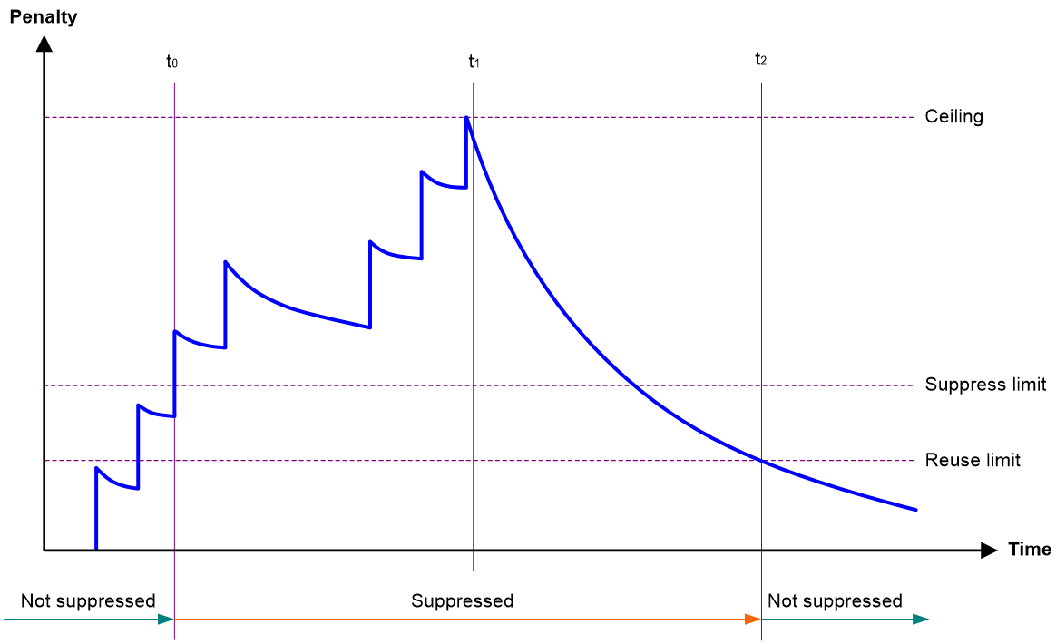
· Penalty—The interface has an initial penalty of 0. When the interface flaps, the penalty increases by 1000 for each down event until the ceiling is reached. It does not increase for up events. When the interface stops flapping, the penalty decreases by half each time the half-life timer expires until the penalty drops to the reuse threshold.
· Ceiling—The penalty stops increasing when it reaches the ceiling.
· Suppress-limit—The accumulated penalty that triggers the device to dampen the interface. In dampened state, the interface does not report its state changes to the CPU. For state change events, the interface only generates SNMP traps and log messages.
· Reuse-limit—When the accumulated penalty decreases to this reuse threshold, the interface is not dampened. Interface state changes are reported to the upper layers. For each state change, the system also generates an SNMP trap and log message.
· Decay—The amount of time (in seconds) after which a penalty is decreased.
· Max-suppress-time—The maximum amount of time the interface can be dampened. If the penalty is still higher than the reuse threshold when this timer expires, the penalty stops increasing for down events. The penalty starts to decrease until it drops below the reuse threshold.
When configuring the dampening command, follow these rules to set the values mentioned above:
· The ceiling is equal to 2(Max-suppress-time/Decay) × reuse-limit. It is not user configurable.
· The configured suppress limit is lower than or equal to the ceiling.
· The ceiling is lower than or equal to the maximum suppress limit supported.
Figure 1 shows the change rule of the penalty value. The lines t0 and t2 indicate the start time and end time of the suppression, respectively. The period from t0 to t2 indicates the suppression period, t0 to t1 indicates the max-suppress-time, and t1 to t2 indicates the complete decay period.
Figure 1 Change rule of the penalty value
Restrictions and guidelines
· The dampening and link-delay commands are mutually exclusive on an interface.
· The dampening command does not take effect on the administratively down events. When you execute the shutdown command, the penalty restores to 0, and the interface reports the down event to the upper-layer protocols.
· Do not enable the dampening feature on an interface with spanning tree protocols enabled.
Procedure
1. Enter system view.
system-view
2. Enter Ethernet interface view.
interface interface-type interface-number
3. Enable dampening on the interface.
dampening [ half-life reuse suppress max-suppress-time ]
By default, interface dampening is disabled on Ethernet interfaces.
Configuring generic flow control on an Ethernet interface
About this task
To avoid dropping packets on a link, you can enable generic flow control at both ends of the link. When traffic congestion occurs at the receiving end, the receiving end sends a flow control (Pause) frame to ask the sending end to suspend sending packets. Generic flow control includes the following types:
· TxRx-mode generic flow control—Enabled by using the flow-control command. With TxRx-mode generic flow control enabled, an interface can both send and receive flow control frames:
¡ When congestion occurs, the interface sends a flow control frame to its peer.
¡ When the interface receives a flow control frame from its peer, it suspends sending packets to its peer.
· Rx-mode generic flow control—Enabled by using the flow-control receive enable command. With Rx-mode generic flow control enabled, an interface can receive flow control frames, but it cannot send flow control frames:
¡ When congestion occurs, the interface cannot send flow control frames to its peer.
¡ When the interface receives a flow control frame from its peer, it suspends sending packets to its peer.
To handle unidirectional traffic congestion on a link, configure the flow-control receive enable command at one end and the flow-control command at the other end. To enable both ends of a link to handle traffic congestion, configure the flow-control command at both ends.
Procedure
1. Enter system view.
system-view
2. Enter Ethernet interface view.
interface interface-type interface-number
3. Enable generic flow control.
¡ Enable TxRx-mode generic flow control.
flow-control
¡ Enable Rx-mode generic flow control.
flow-control receive enable
By default, generic flow control is disabled on an Ethernet interface.
Setting the statistics polling interval
About this task
To display the interface statistics collected in the last statistics polling interval, use the display interface command. To clear the interface statistics, use the reset counters interface command.
Restrictions and guidelines for setting the statistics polling interval
· As a best practice, use the default setting when you set the statistics polling interval in system view. A short statistics polling interval might decrease the system performance and result in inaccurate statistics.
Setting the statistics polling interval in system view
1. Enter system view.
system-view
2. Set the statistics polling interval.
flow-interval interval
By default, the statistics polling interval is 300 seconds.
Enabling subinterface rate statistics collection on an Ethernet interface
Restrictions and guidelines
This feature is resource intensive. When you use this feature, make sure you fully understand its impact on system performance.
After you enable subinterface rate statistics collection on an Ethernet interface, the device periodically refreshes the rate statistics on the subinterfaces of this Ethernet interface.
Procedure
1. Enter system view.
system-view
2. Enter Ethernet interface view.
interface interface-type interface-number
3. Enable subinterface rate statistics collection on the Ethernet interface.
sub-interface rate-statistic
By default, subinterface rate statistics collection is disabled on an Ethernet interface.
4. (Optional.) View the subinterface rate statistics.
display interface
Enabling loopback testing on an Ethernet interface
About this task
Perform this task to determine whether an Ethernet link works correctly.
Loopback testing includes the following types:
· Internal loopback testing—Tests the device where the Ethernet interface resides. The Ethernet interface sends outgoing packets back to the local device. If the device fails to receive the packets, the device fails.
· External loopback testing—Tests the hardware function of the Ethernet interface. The Ethernet interface sends outgoing packets to the local device through a self-loop plug. If the device fails to receive the packets, the hardware function of the Ethernet interface fails.
Restrictions and guidelines
· After you enable this feature on an Ethernet interface, the interface does not forward data traffic.
· The shutdown and loopback commands are mutually exclusive.
· After you enable this feature on an Ethernet interface, the Ethernet interface switches to full duplex mode. After you disable this feature, the Ethernet interface restores to its duplex setting.
Procedure
1. Enter system view.
system-view
2. Enter Ethernet interface view.
interface interface-type interface-number
3. Enable loopback testing.
loopback internal
Restoring the default settings for an interface
Restrictions and guidelines
|
|
CAUTION: This feature might interrupt ongoing network services. Make sure you are fully aware of the impacts of this feature when you use it in a live network. |
This feature might fail to restore the default settings for some commands because of command dependencies or system restrictions. You can use the display this command in interface view to check for these commands and perform their undo forms or follow the command reference to restore their default settings. If your restoration attempt still fails, follow the error message to resolve the problem.
Procedure
1. Enter system view.
system-view
2. Enter Ethernet interface view or Ethernet subinterface view.
interface interface-type { interface-number | interface-number.subnumber }
3. Restore the default settings for the interface.
default
Configuring a Layer 3 Ethernet interface or subinterface
Setting the MTU for an Ethernet interface or subinterface
Restrictions and guidelines
The maximum transmission unit (MTU) of an Ethernet interface affects the fragmentation and reassembly of IP packets on the interface. Typically, you do not need to modify the MTU of an interface.
Procedure
1. Enter system view.
system-view
2. Enter interface view.
interface interface-type { interface-number | interface-number.subnumber }
3. Set the interface MTU.
mtu size
The default setting is 1500 bytes.
Changing the interface type
About this task
You can change the interface type between POS and GigabitEthernet.
Restrictions and guidelines
When you change the interface type, the system removes the original interface, and then creates a new-type interface with the same number as the original interface.
Changing a Layer 3 GigabitEthernet interface to a standard POS interface
1. Enter system view.
system-view
2. Enter Layer 3 GigabitEthernet interface view.
interface gigabitethernet interface-number
3. Change the interface to a standard POS interface.
port-type switch pos
The device enters standard POS interface view automatically after you execute this command.
Changing a standard POS interface to a Layer 3 GigabitEthernet interface
1. Enter system view.
system-view
2. Enter standard POS interface view.
interface pos interface-number
3. Change the interface to a Layer 3 GigabitEthernet interface.
port-type switch gigabitethernet
The device enters Layer 3 GigabitEthernet interface view automatically after you execute this command.
Enabling statistics collection on a Layer 3 Ethernet subinterface
About this task
This feature is resource intensive. When you use this feature, make sure you fully understand its impact on system performance.
Procedure
1. Enter system view.
system-view
2. Enter Layer 3 Ethernet subinterface view.
interface interface-type interface-number.subnumber
3. Enable statistics collection on the Layer 3 Ethernet subinterface.
traffic-statistic enable
By default, statistics collection is disabled on a Layer 3 Ethernet subinterface.
4. (Optional.) Display the subinterface traffic statistics.
display interface
display counters
The Input and Output fields in the display interface command output display the subinterface traffic statistics.
Display and maintenance commands
Execute display commands in any view and reset commands in user view.
|
Task |
Command |
|
Display interface traffic statistics. |
display counters { inbound | outbound } interface [ interface-type [ interface-number | interface-number.subnumber ] ] |
|
Display traffic rate statistics of interfaces in up state over the last statistics polling interval. |
display counters rate { inbound | outbound } interface [ interface-type [ interface-number | interface-number.subnumber ] ] |
|
Display the Ethernet module statistics. |
In standalone mode: display ethernet statistics slot slot-number In IRF mode: display ethernet statistics chassis chassis-number slot slot-number |
|
Display the operational and status information of the specified interfaces. |
display interface [ interface-type [ interface-number | interface-number.subnumber ] ] [ brief [ description | down ] ] |
|
Display information about dropped packets on the specified interfaces. |
display packet-drop { interface [ interface-type [ interface-number ] ] | summary } |
|
Clear interface statistics. |
reset counters interface [ interface-type [ interface-number | interface-number.subnumber ] ] |
|
Clear the Ethernet module statistics. |
In standalone mode: reset ethernet statistics [ slot slot-number ] In IRF mode: reset ethernet statistics [ chassis chassis-number slot slot-number ] |
|
Clear the statistics of dropped packets on the specified interfaces. |
reset packet-drop interface [ interface-type [ interface-number ] ] |
