- Table of Contents
- Related Documents
-
| Title | Size | Download |
|---|---|---|
| 07-SRST configuration | 1.00 MB |
Contents
Call services supported by SRST
Restrictions: Hardware compatibility with SRST
Restrictions: Licensing requirements for SRST
Configuring SIP registration parameters
Configuring the keepalive feature
Configuring call services supported by SRST
Display and maintenance commands for SRST
Example: Configuring the SIP registrar
Example: Configuring the keepalive feature
Example: Configuring PSTN backup
Example: Configuring basic call services
Example: Configuring call pickup
Example: Configuring call forwarding
Example: Configuring call blocking
Example: Configuring FACs on a gateway
Example: Configuring FACs for the call forwarding service on a voice server
Example: Configuring FACs for the call pickup service on a voice server
Configuring SRST
About SRST
Survivable Remote Site Telephony (SRST) provides backup call management when the remote voice server is not accessible.
Typical SRST network
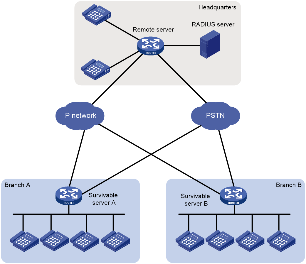
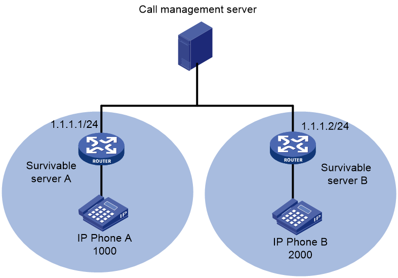
As shown in Figure 1, the remote server (remote primary voice server) is in the headquarters. Survivable server A and Survivable server B (local survivable voice servers) are in the branches. The remote server manages calls from and to branch office IP phones through WAN links.
When the remote server is not accessible, IP phones are connected to the PSTN network through the local survivable servers. Survivable server A and Survivable server B take over call management, and IP phones can place and receive calls. When the remote server is accessible, call handling reverts back to the remote server.
Operating modes
A voice server can operate in the following modes:
· Remote mode—A voice server that operates in remote mode provides call management services.
· Local survivable mode—A voice server that operates in local survivable mode provides backup call management services when the remote voice server is not accessible.
In this document, a remote server refers to a remote voice server, and a survivable server refers to a local survivable voice server.
SIP registrar
Voice servers can act as SIP registrars, and SIP UAs are required to register with SIP registrars. During SIP UA registration, remote servers can challenge and authenticate SIP UAs, but survivable servers cannot.
As shown in Figure 2, IP phone A and IP phone B register with both the survivable server and the remote server. The remote server authenticates the two IP phones.
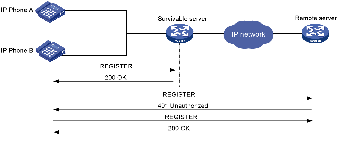
For more information about SIP registration, see "Configuring SIP."
VoIP entities in SRST
SRST introduces dynamic VoIP entities and distinguishes incoming and outgoing VoIP entities.
Dynamic VoIP entities
Dynamic VoIP entities are automatically created by the system.
Based on registration status, dynamic VoIP entities include the following types:
· Registered dynamic VoIP entity—Created after a SIP UA successfully registers with the remote server and the survivable server.
On the survivable server, two dynamic VoIP entities are created. Call destinations for the dynamic VoIP entities are the SIP UA and the remote server. On the remote server, only one dynamic incoming VoIP entity is created. The call destination for the dynamic VoIP entity is the SIP UA. If multiple SIP UAs with the same number register with the remote server, only one dynamic VoIP entity is created. The dynamic VoIP entity is deleted only when all the SIP UAs unregister from the remote server.
Registered dynamic VoIP entities are numbered from 40001. If a number greater than 40000 is used by a statically configured POTS or VoIP entity, the number is skipped.
· Unregistered dynamic VoIP entity—Created after call forwarding is configured in directory numbers (DNs) for SIP UAs that do not register with the voice server.
For more information about call forwarding, see "Configuring call forwarding." For more information about DNs, see "Configuring DNs."
You cannot modify or delete dynamic VoIP entities. Dynamic VoIP entities might be deleted if one of the following conditions occurs:
· The global register pool view is removed.
· A remote server is removed.
· The operation mode of a voice server is changed.
· The registration requirements for SIP UAs are changed.
Incoming and outgoing VoIP entities
Based on call direction, VoIP entities include the following types:
· Incoming VoIP entity—Matches an incoming call. An incoming VoIP entity maintains registration credentials and call attributes. Only calls whose calling number and call destination match an incoming VoIP entity can be placed.
· Outgoing VoIP entity—Matches an outgoing call. An outgoing VoIP entity maintains the called information such as called number and call destination.
VoIP entity selection order
When a call arrives, the voice server first looks up a matching dynamic VoIP entity. If no match is found, it looks up a matching static VoIP entity according to the configured entity selection order. For more information about entity selection orders, see "Configuring dial programs."
Keepalive feature
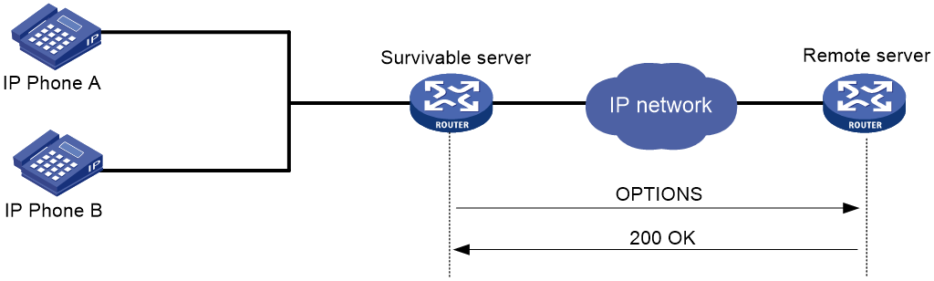
The keepalive feature enables a survivable server to check the availability of a remote server by sending OPTIONS messages.
Figure 3 describes the keepalive process:
1. The survivable server periodically sends an OPTIONS message to the remote server.
2. If the remote server is available, it replies with a 200 OK response.
If the remote server is not available, the survivable server receives an error response or does not receive a response in the specified time. In this case, the survivable server takes over to manage calls for the local site.
PSTN backup
The survivable server can use the PSTN as a fallback when the WAN link goes down. If POTS entities exist, the following calls can be established over the PSTN network:
· Calls within a branch.
· Calls between different branches.
· Calls between a branch and the headquarters.
For more information about configuring POTS entities for PSTN backup, see "Example: Configuring PSTN backup."
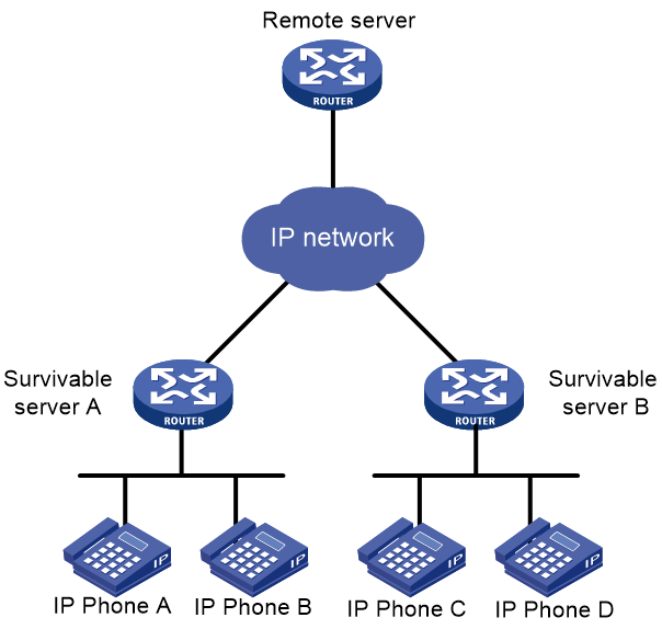
Basic call flow
As shown in Figure 4, IP phone A and IP phone B successfully register with Survivable server A and the remote server. IP phones C and D successfully register with Survivable server B and the remote server.
Call flow for basic calls within a branch
The following shows the call flow from IP phone A to IP phone B:
· Survivable server A is the call destination on IP phone A:
a. IP phone A places a call to IP phone C.
b. The call arrives at Survivable server A. Survivable server A uses the matching static VoIP entity to forward the call to the remote server. In the static VoIP entity, the called number is IP phone C and the call destination is the remote server.
c. The call arrives at the remote server. The remote server uses a matching static incoming VoIP entity to authenticate the calling party.
d. The remote server uses a matching dynamic VoIP entity to forward the call to IP phone B. In the dynamic VoIP entity, the call destination is IP phone B.
e. IP phone B receives the call.
· The remote server is the call destination on IP phone A:
a. IP phone A places a call to IP phone B.
b. The call arrives at the remote server. The remote server uses the matching dynamic VoIP entity to forward the call to IP phone B. In the dynamic VoIP entity, the call destination is IP phone B.
c. IP phone B receives the call.
If the remote server is not accessible, Survivable server A and Survivable server B manage calls within the branches, respectively.
Call flow for basic calls between different branches
The following shows the call flow from IP phone A to IP phone C:
· Survivable server A is the call destination on IP phone A:
a. IP phone A places a call to IP phone C.
b. The call arrives at Survivable server A. Survivable server A uses the matching static VoIP entity to forward the call to the remote server. In the static VoIP entity, the called number is IP phone C and the call destination is the remote server.
c. The call arrives at the remote server. The remote server uses the matching dynamic VoIP entity to forward the call to IP phone C. In the dynamic VoIP entity, the call destination is IP phone C.
d. IP phone C receives the call.
· The remote server is the call destination on IP phone A:
a. IP phone A places a call to IP phone C.
b. The call arrives at the remote server. The remote server uses the matching dynamic VoIP entity to forward the call to IP phone C. In the dynamic VoIP entity, the call destination is IP phone C.
c. IP phone C receives the call.
If the remote server is not accessible, Survivable server A and Survivable server B use the PSTN network to manage calls between the branches.
Call services supported by SRST
SRST supports the following call services: call blocking, call forwarding, Do Not Disturb (DND), Feature Access Codes (FACs), Music On Hold (Music On Hold), and MWI.
Restrictions: Hardware compatibility with SRST
|
Hardware |
SRST compatibility |
|
MSR810, MSR810-W, MSR810-W-DB, MSR810-LM, MSR810-W-LM, MSR810-10-PoE, MSR810-LM-HK, MSR810-W-LM-HK, MSR810-LM-CNDE-SJK, MSR810-CNDE-SJK |
Yes for only PSTN backup |
|
MSR810-LMS, MSR810-LUS |
No |
|
MSR810-LMS-EA, MSR810-LME |
No |
|
MSR2600-6-X1 |
No |
|
MSR2600-10-X1 |
Yes |
|
MSR 2630 |
Yes |
|
MSR3600-28, MSR3600-51 |
Yes |
|
MSR3600-28-SI, MSR3600-51-SI |
No |
|
MSR3600-28-X1, MSR3600-28-X1-DP, MSR3600-51-X1, MSR3600-51-X1-DP |
No |
|
MSR3610-I-DP, MSR3610-IE-DP, MSR3610-IE-ES, MSR810-CNDE-SJK |
No |
|
MSR3610-X1, MSR3610-X1-DP, MSR3610-X1-DC, MSR3610-X1-DP-DC |
Yes |
|
MSR 3610, MSR 3620, MSR 3620-DP, MSR 3640, MSR 3660 |
Yes |
|
MSR3610-G, MSR3620-G |
No |
|
Hardware |
Dial program compatibility |
|
MSR810-W-WiNet, MSR810-LM-WiNet |
Yes for only PSTN backup |
|
MSR830-4LM-WiNet |
No |
|
MSR830-5BEI-WiNet, MSR830-6EI-WiNet, MSR830-10BEI-WiNet |
No |
|
MSR830-6BHI-WiNet, MSR830-10BHI-WiNet |
No |
|
MSR2600-6-WiNet |
No |
|
MSR2600-10-X1-WiNet |
Yes |
|
MSR2630-WiNet |
Yes |
|
MSR3600-28-WiNet |
Yes |
|
MSR3610-X1-WiNet |
Yes |
|
MSR3610-WiNet, MSR3620-10-WiNet, MSR3620-DP-WiNet, MSR3620-WiNet, MSR3660-WiNet |
Yes |
|
Hardware |
SRST compatibility |
|
MSR2630-XS |
No |
|
MSR3600-28-XS |
No |
|
MSR3610-XS |
Yes |
|
MSR3620-XS |
Yes |
|
MSR3610-I-XS |
No |
|
MSR3610-IE-XS |
No |
|
Hardware |
SRST compatibility |
|
MSR810-LM-GL |
Yes for PSTN backup |
|
MSR810-W-LM-GL |
Yes for PSTN backup |
|
MSR830-6EI-GL |
No |
|
MSR830-10EI-GL |
No |
|
MSR830-6HI-GL |
No |
|
MSR830-10HI-GL |
No |
|
MSR2600-6-X1-GL |
No |
|
MSR3600-28-SI-GL |
No |
Restrictions: Licensing requirements for SRST
To support SRST, some device models require the Voice Software License. For more information, see license management in Fundamentals Configuration Guide.
SRST tasks at a glance
To configure SRST, perform the following tasks:
a. Specifying the operating mode
b. Configuring the SIP registrar
c. Configuring SIP registration parameters
e. Configuring the keepalive feature
Perform this task only on the remote server.
f. (Optional.) Configuring DNs
3. Configuring call services supported by SRST
Choose the options to configure as needed.
Configuring a voice server
Specifying the operating mode
1. Enter system view.
system-view
2. Enter voice view.
voice-setup
3. Create a global register pool and enter its view.
voice register global
4. Specify the operation mode.
¡ Configure the device to operate as a survivable server.
mode alive
¡ Configure the device to operate as a remote server.
mode alone
By default, the device does not act as a voice server.
Configuring the SIP registrar
About this task
When the device acts as a SIP voice gateway or SIP trunk, it cannot process SIP register messages. For a device to process SIP register messages, configure the device as the SIP registrar.
Procedure
1. Enter system view.
system-view
2. Enter voice view.
voice-setup
3. Enter SIP view.
sip
4. Enable the SIP registrar and set the global registration expiration time.
registrar server [ expires { max max | min min } * ]
By default, the SIP registrar is disabled.
Configuring SIP registration parameters
About this task
For the voice server to successfully accept SIP UA registration, you must set the maximum numbers of register pools and DNs to non-zero values.
To allow a remote server to authenticate SIP UAs, enable SIP register authentication and configure credentials for authentication.
Procedure
1. Enter system view.
system-view
2. Enter voice view.
voice-setup
3. Enter the global register pool view.
voice register global
4. Set the maximum number of register pools.
max-pool max-pool
By default, the maximum number of register pools is 0.
5. Set the maximum number of DNs.
max-dn max-dn
By default, the maximum number of DNs is 0.
6. (Optional.) Enable SIP register authentication.
authenticate register
By default, SIP register authentication is disabled.
Use this command only on the remote server.
7. (Optional.) Configure the realm name carried in 401 responses.
authenticate realm string
By default, no realm name is carried in 401 responses.
Use this command only on the remote server.
8. (Optional.) Configure credentials.
username username password { cipher | simple } string
By default, a voice server does not authenticate SIP UAs during registration.
This configuration will not be synchronized to dynamic VoIP entities.
Use this command only on the remote server.
Configuring register pools
About this task
A register pool contains registration requirements that define which SIP UAs can register and also maintains registration information of SIP UAs. If a SIP UA meets the registration requirements of a register pool on a voice server, it successfully registers with the voice server. Then, a dynamic VoIP entity is created, and it inherits configurations in the register pool.
If multiple register pools exist, a SIP UA matches registration requirements in register pools in the ascending order of their tags.
If multiple register number templates exist in a register pool, the SIP UA matches these templates in the ascending order of their tags.
Configuration guidelines
A register number template defines a template for numbers that can register with the voice server. For example, if you execute the number 1000 command, all numbers beginning with 1000 (such as 10001, 10002, and 10003) can register with the voice server. If you execute the number 1000$ command, only the number 1000 can register with the voice server.
All successfully registered numbers end with a dollar sign ($) in the command output. To view numbers that have successfully registered, use the display voice register entity or display voice register pool all brief command.
If you configure both the number and id commands for a register pool, only SIP UAs with matching phone numbers and addresses successfully register.
SIP UAs can register with a voice server only by its own address, number, or both but not by the realm name of the voice server.
As a best practice, do not configure the voice server to process registration based on a MAC address if SIP UAs use TCP or TLS to transmit register messages.
Procedure
1. Enter system view.
system-view
2. Enter voice view.
voice-setup
3. Create a register pool and enter its view.
voice register pool pool-tag
4. Configure registration requirements for SIP UAs. Choose one option as needed:
¡ Specify SIP UAs that can register with the voice server.
id { ip ip-address | network network [ mask { mask-length | mask } ] | mac mac-address }
¡ Configure a register number template.
number tag { number | dn dn-tag }
If you configure the register number template by using the dn dn-tag option, you must specify an existing DN. For more information about configuring DNs, see "Configuring DNs."
By default, no registration requirements are configured and any SIP UAs can register.
5. (Optional.) Set the registration expiration time.
registration-timer max max min min
By default, the global registration expiration time applies.
This configuration will not be synchronized to dynamic VoIP entities in the register pool.
6. (Optional.) Set the priority for dynamic VoIP entities in the register pool.
priority priority
By default, the priority of dynamic VoIP entities in a register pool is 0.
The smaller the value, the higher the priority.
7. (Optional.) Enable out-of-band DTMF.
outband { nte | sip }
By default, inband DTMF is used.
8. (Optional.) Apply a number substitution rule list to the register pool.
substitute { called | calling } list-number
By default, no number substitution rule is applied to a register pool. No number substitution is performed.
9. (Optional.) Configure a codec for the register pool. Choose one option as needed:
¡ Configure a codec for the register pool.
codec { g711alaw | g711ulaw | g723r53 | g723r63 | g726r16 | g726r24 | g726r32 | g726r40 | g729a | g729br8 | g729r8 } [ bytes payload-size ]
By default, no codec is configured for a register pool.
¡ Apply a codec template to the register pool.
voice-class codec tag
By default, no codec template is applied to a register pool.
10. (Optional.) Bind a subscriber group to the register pool to permit or deny calls from numbers in the subscriber group.
caller-group { deny | permit } group-id
By default, no subscriber group is bound to a register pool.
Configuring the keepalive feature
About this task
For a survivable server to regularly check the availability of the remote server, you must configure the keepalive feature.
Configuration guidelines
Perform this task only on survivable servers.
The configuration in a register pool will not be synchronized to dynamic VoIP entities in the register pool.
Procedure
1. Enter system view.
system-view
2. Enter voice view.
voice-setup
3. Create a register pool and enter its view.
voice register pool pool-tag
By default, no register pools exist.
4. Specify remote voice servers and enable the keepalive feature.
proxy ip ip1 [ port main-port-number ] [ monitor probe sip [ ip2 [ port backup-port-number ] ] ] [ priority priority ]
5. (Optional.) Set keepalive parameters.
voice-class sip options-keepalive [ up-interval interval ] [ down-interval interval ] [ retry retries ]
By default, the up-interval is 60 seconds, the down-interval is 30 seconds, and the retry is 5 times.
Use the up-interval and down-interval keywords to set the interval for sending OPTIONS packets when the remote server is available or unavailable, respectively.
Configuring DNs
About this task
DNs allow you to make configurations specific to SIP UAs with matching phone numbers. Dynamic VoIP entities created for these numbers inherit the configurations in the DN rather than those in the register pool where VoIP entities are created.
Configuration guidelines
A register number template defines a template for numbers that can register with the voice server. For example, if you execute the number 1000 command, all numbers beginning with 1000 (such as 10001, 10002, and 10003) can register with the voice server. If you execute the number 1000$ command, only number 1000 can register with the voice server.
All successfully registered numbers end with a dollar sign ($) in the command output. To view numbers that have successfully registered, use the display voice register entity or display voice register pool all brief command.
You can configure only one register number template for a DN.
DN-specific configuration takes priority over register pool-specific configuration. For example, dynamic VoIP entities are created for IP phones on the subnet 10.1.1.0 in a register pool. The priority of the dynamic VoIP entities in the register pool is 3. To change the priority of dynamic VoIP entity to 1 for the phone with number 1000, perform the following tasks:
1. Create a DN.
2. Set the register number template for the DN to 1000.
3. Set the priority of dynamic VoIP entities in the DN to 1.
4. Apply the DN to the register pool.
Procedure
1. Enter system view.
system-view
2. Enter voice view.
voice-setup
3. Create a DN and enter its view.
voice register dn dn-tag
4. Configure a register number template for the DN.
number number
By default, no register number template is configured for a DN.
5. Set the priority for dynamic VoIP entities in the DN.
priority priority
By default, the priority of dynamic VoIP entities in a DN is 0.
The smaller the value, the higher the priority.
Configuring basic calling
1. Enable SIP-to-SIP calling.
allow-connections sip to sip
For more information about this command, see SIP commands in Voice Command Reference.
2. Configure VoIP entities.
a. Configure outgoing VoIP entities that can forward calls to terminating devices.
b. Configure incoming VoIP entities to define call attributes for incoming calls.
For more information about VoIP entity configuration, see "Configuring voice entities."
Configuring call services supported by SRST
Configuring MOH
About this task
MOH is a music stream that is played to an IP phone user who is placed on hold. To save bandwidth, you can configure local voice servers as MOH resources to provide MOH. This eliminates the need to transmit MOH across a WAN.
You can configure the local voice server to unicast or multicast MOH streams. For more information about unicasting MOH streams, see "Configuring call services." The following example shows the process of multicasting MOH streams.
As shown in Figure 5, IP phone A and the survivable server belong to a branch. The call management server and the survivable server are configured with the MOH multicast address 239.1.1.2 and port 2009.
Figure 5 Voice server as the MOH multicast resource
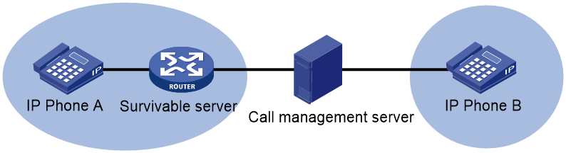
MOH is multicast as follows:
1. IP phone B holds the call from IP phone A.
2. The call management server receives the Re-Invite message for call hold from IP phone B. It sends the MOH multicast address and port number to IP phone A that is being held.
3. IP phone A joins the multicast group and receives the MOH stream.
Procedure
1. Enter system view.
system-view
2. Enter voice view.
voice-setup
3. Enter the global register pool view.
voice register global
4. Configure MOH. Choose one option as needed:
¡ Configure the device to multicast MOH.
multicast moh ip multicast-address port port-number route address-list
¡ Configure the device to unicast MOH.
call-hold-format sendonly
By default, no MOH multicast address is configured, and the call hold mode is inactive.
5. Specify an MOH resource file.
moh file filename
Configuring solicited MWI
About this task
When you configure MWI on the device, registered numbers in a DN can subscribe to the MWI service.
For more information about MWI, see "Configuring call services."
Procedure
1. Enter system view.
system-view
2. Enter voice view.
voice-setup
3. Enter SIP view.
sip
4. Configure the voice mail server.
mwi-server { dns domain-name | ip ip-address } [ port port-number ] [ expires seconds ] [ transport { tcp [ tls ] | udp } ] [ scheme { sip | sips } ]
5. Return to voice view.
quit
6. Create a DN and enter DN view.
voice register dn dn-tag
7. Enable MWI for the DN.
mwi
By default, MWI is disabled for a DN.
Configuring call pickup
About this task
Call pickup allows users to answer a call on their own phones when the call is destined for another phone.
Call pickup includes the following types:
· Direct call pickup—Allows users to answer any calls by pressing the GPickUp softkey and dialing the called numbers.
· Local group pickup—Allows users to answer calls within their own pickup group by using either of the following methods:
¡ Press the PickUp softkey.
¡ Press the GPickUp softkey and the asterisk (*) key.
· Group pickup—Allows users to answer calls for other pickup groups by pressing the GPickUp softkey and dialing the pickup group numbers. If called numbers do not belong to any pickup groups, users can answer calls by pressing the GPickUp softkey and the asterisk (*) key.
Configuration guidelines
You can implement direct call pickup without making any configurations on the voice server.
IP phones support call pickup. For non-IP phones to support call pickup, configure FACs on the voice server and activate call pickup by pressing the predefined FACs on the phones. For more information about FACs, see "Configuring FACs."
Procedure
1. Enter system view.
system-view
2. Enter voice view.
voice-setup
3. Create a DN and enter its view.
voice register dn dn-tag
4. Assign the DN to a pickup group.
pickup-group group-name
By default, a DN does not belong to any pickup group.
5. Enable the GPickUp softkey for group pickup.
pickup-call any-group
By default, the GPickUp softkey for group pickup is disabled.
Enabling DND
About this task
DND blocks incoming calls to numbers in a register pool with a 486 response. When a call is blocked, the calling party hears busy tones. DND does not block outgoing calls.
Configuration guidelines
In a register pool, call blocking takes priority over DND, and DND takes priority over call forwarding.
Procedure
1. Enter system view.
system-view
2. Enter voice view.
voice-setup
3. Enter SIP view.
sip
4. Create a register pool and enter its view.
voice register pool pool-tag
5. Enable DND.
dnd
By default, DND is disabled.
Configuring call forwarding
About this task
Call forwarding allows incoming calls for a number to be forwarded to another number. Incoming calls will be forwarded only if the dynamic VoIP entity created for the number is configured with call forwarding.
A voice server supports the following types of call forwarding:
· Call forwarding unconditional.
· Call forwarding busy.
· Call forwarding no reply.
· Call forwarding unregistered.
Configuration guidelines
You can configure call forwarding unconditional, call forwarding busy, and call forwarding no reply in register pool view or DN view. However, you can configure call forwarding unregistered only in DN view.
In a register pool, call blocking takes priority over DND, and DND takes priority over call forwarding.
You must correctly plan forward-to numbers to avoid incorrect numbers and circular calls.
You can configure a call to be forwarded a maximum of five times.
Configuring call forwarding in DN view
1. Enter system view.
system-view
2. Enter voice view.
voice-setup
3. Create a DN and enter its view.
voice register dn dn-tag
4. Configure call forwarding.
call-forward b2bua { all number | busy number | noan number [ timeout seconds ] | unregistered number }
By default, call forwarding is disabled in DN view.
Configuring call forwarding in register pool view
1. Enter system view.
system-view
2. Enter voice view.
voice-setup
3. Create a register pool and enter its view.
voice register pool pool-tag
4. Configure call forwarding.
call-forward b2bua { all number | busy number | noan number [ timeout seconds ] }
By default, call forwarding is disabled in register pool view.
Configuring call blocking
About this task
Call blocking prevents unauthorized use of phones during a specified time period. If calls whose called numbers match the specified template, the system blocks the calls with a 500 response. The calling party hears busy tones.
You can also configure the voice server to exempt specific numbers from call blocking.
Configuration guidelines
Call blocking does not block outgoing calls for numbers that match the specified template.
In a register pool, call blocking takes priority over DND, and DND takes priority over call forwarding.
Procedure
1. Enter system view.
system-view
2. Enter voice view.
voice-setup
3. Enable call blocking and configure the number template to be blocked.
after-hours block pattern pattern-tag pattern [ 7-24 ]
By default, call blocking is disabled.
If a called number matches multiple patterns, the pattern with the lowest tag applies.
4. Define a time period for call blocking based on the month and date.
after-hours date month date start-time stop-time
By default, no time period for call blocking is defined based on the month and date.
5. Define a time period for call blocking based on the day of the week.
after-hours day day start-time stop-time
By default, no time period for call blocking is defined based on the day of the week.
6. Create a DN and enter its view.
voice register dn dn-ag
7. Exempt numbers in the DN from call blocking.
after-hours exempt
By default, call blocking applies to all numbers in a DN.
Configuring FACs
About this task
FACs are special patterns of characters predefined on the device to invoke voice services. Phone users can dial these FACs on their phones to enable or disable corresponding voice services with the device. For example, a phone user can dial *57* and then dial 1000 to forward all incoming calls to phone number 1000.
You can enable standard FACs (see Table 1) or configure custom FACs.
The terminator for FACs notifies the device that no digit follows the terminator. The terminator for standard FACs is a pound sign (#), which is not user configurable. You can configure the terminator for custom FACs.
|
Standard FAC |
Description |
|
*40* |
Enables the call forwarding busy service. |
|
#40# |
Disables the call forwarding busy service. |
|
*41* |
Enables the call forwarding no reply service. |
|
#41# |
Disables the call forwarding no reply service. |
|
*44* |
Enables the call forwarding unregistered service. |
|
#44# |
Disables the call forwarding unregistered service. |
|
*57* |
Enables the call forwarding unconditional service. |
|
#57# |
Disables the call forwarding unconditional service. |
|
*70* |
Enables the DND service. |
|
#70# |
Disables the DND service. |
|
*80* |
Enables the direct pickup service. |
|
*81* |
Enables the local group pickup service. |
|
*82* |
Enables the group pickup service. |
Configuration guidelines
A voice server supports all FACs. A voice gateway supports only FACs for call forwarding services (excluding call forwarding unregister service and call forwarding unavailable service).
When the device acts as a voice server, FACs take effect only on IP phones that successfully register with the voice server. However, if you want to enable the call forwarding unregistered service on a registered phone, you must deregister the phone from the voice server.
FACs on IP phones modify configurations of dynamic VoIP entities created for the IP phones. They do not change the configurations in register pools.
Executing undo forms of call service commands cannot disable call services if the call services are registered only through FACs.
The device can accept a maximum of 31 dialed digits including the terminator.
When you configure custom FACs, follow these guidelines to avoid problems:
· Assign each voice service a unique FAC.
· Make sure FACs for registration and FACs for deregistration do not include the same leading characters.
· Make sure the FAC plus the target number for registering a voice service does not overlap with another FAC.
Procedure
1. Enter system view.
system-view
2. Enter voice view.
voice-setup
3. Configure FACs. Choose one option as needed:
¡ Enable standard FACs.
fac standard
By default, standard FACs are disabled.
¡ Configure custom FACs.
fac custom { alias id custom-string to existing-string | callfwd { all | all-cancel | busy | busy-cancel | noan | noan-cancel | unregistered | unregistered-cancel } string | dnd [ cancel ] string | pickup { direct | group | local } string }
By default, no custom FACs are used.
Assign each voice service a unique FAC.
4. Configure the terminator for custom FACs.
fac terminator character
By default, the terminator for custom FACs is a pound sign (#).
This command takes effect only on a SIP gateway configured with custom FACs.
Display and maintenance commands for SRST
Execute display commands in any view.
|
Task |
Command |
|
Display information about dynamic VoIP entities created in register pools. |
display voice register entity { pool tag | all } |
|
Display registration information in register pools. |
display voice register pool all brief |
|
Display configurations of voice entities. |
display voice entity { entity-tag | all | pots | voip } |
|
Display FACs. |
display voice fac |
SRST configuration examples
Example: Configuring the SIP registrar
Network configuration
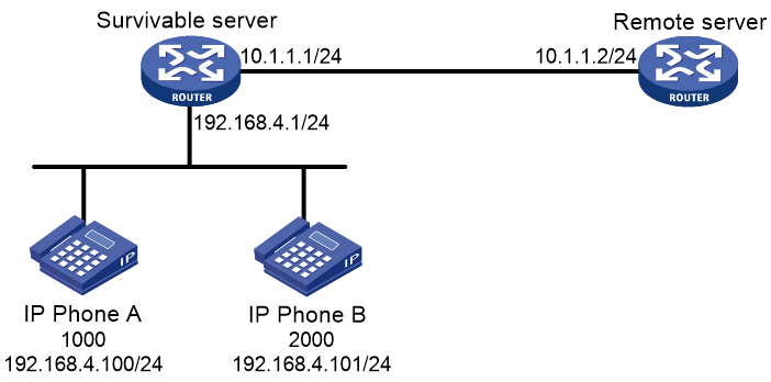
As shown in Figure 6, the remote server processes calls between IP phone A and IP phone B.
Configure the SIP registrar feature on the survivable server and the remote server. Then, IP phone A and IP phone B can call each other when the remote server is not accessible.
Procedure
1. Configure the survivable server:
# Enable SIP-to-SIP calling.
<Survivable> system-view
[Survivable] voice-setup
[Survivable-voice] allow-connections sip to sip
# Enable the SIP registrar.
[Survivable-voice] sip
[Survivable-voice-sip] registrar server
[Survivable-voice-sip] quit
# Specify the local survivable mode, and set the maximum numbers to 10 for both register pools and DNs.
[Survivable] voice-setup
[Survivable-voice] voice register global
[Survivable-voice-register-global] mode alive
[Survivable-voice-register-global] max-pool 10
[Survivable-voice-register-global] max-dn 10
[Survivable-voice-register-global] quit
# Create DN 1, configure the register number template as 1000, and set the priority for dynamic VoIP entities to 1.
[Survivable-voice] voice register dn 1
[Survivable-voice-register-dn1] number 1000$
[Survivable-voice-register-dn1] priority 1
[Survivable-voice-register-dn1] quit
# Create register pool 1, and permit IP phone A with IP address 192.168.4.100 to register.
[Survivable-voice] voice register pool 1
[Survivable-voice-register-pool1] id ip 192.168.4.100
# Apply the register number template of DN 1 to register pool 1, and set the priority for dynamic VoIP entities to 2.
[Survivable-voice-register-pool1] number 1 dn 1
[Survivable-voice-register-pool1] priority 2
# Specify the remote server as the remote voice server and enable the keepalive feature.
[Survivable-voice-register-pool1] proxy ip 10.1.1.2 monitor probe sip
[Survivable-voice-register-pool1] quit
# Create register pool 2, and permit IP phone B with IP address 192.168.4.101 to register.
[Survivable-voice] voice register pool 2
[Survivable-voice-register-pool2] id ip 192.168.4.101
# Configure the register number template to 2000, and set the priorities of dynamic VoIP entities to 3.
[Survivable-voice-register-pool2] number 1 2000$
[Survivable-voice-register-pool2] priority 3
# Specify the remote voice server as the remote server.
[Survivable-voice-register-pool2] proxy ip 10.1.1.2
[Survivable-voice-register-pool2] quit
# Display registration information in all register pools.
[Survivable-voice] display voice register pool all brief
Pool ID IP Address Ln DN Number State
-----------------------------------------------------------------------------
1 192.168.4.100 1 1 1000 Unregistered
2 192.168.4.101 1 2000 Unregistered
The output shows that IP phone A and IP phone B do not register with the survivable server.
# Display information about all dynamic VoIP entities created in register pools.
[Survivable-voice] display voice register entity all
Entities created dynamically on register pool 1:
There are no entities in this pool.
Entities created dynamically on register pool 2:
There are no entities in this pool.
2. Configure the remote server:
# Enable SIP-to-SIP calling.
<Remote> system-view
[Remote] voice-setup
[Remote-voice] allow-connections sip to sip
# Enable the SIP registrar.
[Remote-voice] sip
[Remote-voice-sip] registrar server
[Remote-voice-sip] quit
# Specify the remote mode, and set the maximum numbers to 10 for both register pools and DNs.
[Remote] voice-setup
[Remote-voice] voice register global
[Remote-voice-register-global] mode alone
[Remote-voice-register-global] max-pool 10
[Remote-voice-register-global] max-dn 10
[Remote-voice-register-global] quit
# Create DN 1, configure the register number template as 1000, and set the priority of dynamic VoIP entities to 1.
[Remote] voice-setup
[Remote-voice] voice register dn 1
[Remote-voice-register-dn1] number 1000$
[Remote-voice-register-dn1] priority 1
[Remote-voice-register-dn1] quit
# Create register pool 1, permit IP phone A with IP address 192.168.4.100 to register, and set the priority of dynamic VoIP entities to 2.
[Remote] voice-setup
[Remote-voice] voice register pool 1
[Remote-voice-register-pool1] id ip 192.168.4.100
[Remote-voice-register-pool1] number 1 dn 1
[Remote-voice-register-pool1] priority 2
[Remote-voice-register-pool1] quit
# Create register pool 2, permit IP phone B with IP address 192.168.4.101 to register, and set the priority of dynamic VoIP entities to 3.
[Remote-voice] voice register pool 2
[Remote-voice-register-pool2] id ip 192.168.4.101
[Remote-voice-register-pool2] number 1 2000$
[Remote-voice-register-pool2] priority 3
[Remote-voice-register-pool2] quit
# Display registration information in all register pools.
[Remote-voice] display voice register pool all brief
Pool ID IP Address Ln DN Number State
-----------------------------------------------------------------------------
1 192.168.4.100 1 1 1000 Unregistered
2 192.168.4.101 1 2000 Unregistered
The output shows that IP phone A and IP phone B do not register with the remote server.
# Display information about dynamic VoIP entities created in register pools.
[Remote-voice] display voice register entity all
Entities created dynamically on register pool 1:
There are no entities in this pool.
Entities created dynamically on register pool 2:
There are no entities in this pool.
Verifying the configuration
1. Verify that IP phone A and IP phone B can register with the survivable server.
# Register IP phone A and IP phone B with the survivable server. (Details not shown.)
# Display registration information for all register pools on the survivable server.
[Survivable] display voice register pool all brief
Pool ID IP Address Ln DN Number State
------------------------------------------------------------------------------
1 192.168.4.100 192.168.4.100 1 1 1000$ Registered
2 192.168.4.101 192.168.4.101 1 2000$ Registered
The output shows that IP phone A and IP phone B have successfully registered with the survivable server.
# Display information about dynamic VoIP entities on the survivable server.
[Survivable] display voice register entity all
Entities created dynamically on register pool 1:
entity 40001 voip
match-template 1000$
address sip ip 192.168.4.100 port 10002
session transport udp
priority 1
entity 40002 voip
match-template 1000$
address sip ip 10.1.1.2 port 5060
session transport global
Entities created dynamically on register pool 2:
entity 40003 voip
match-template 2000$
address sip ip 192.168.4.101 port 10003
session transport udp
priority 3
entity 40004 voip
match-template 2000$
address sip ip 10.1.1.2 port 5060
session transport global
The output shows the following information:
¡ In register pool 1, dynamic VoIP entities 40001 and 40002 are created, with call destinations as IP phone A and the remote server, respectively.
¡ In register pool 2, dynamic VoIP entities 40003 and 40004 are created, with call destinations as IP phone B and the remote server, respectively.
2. Verify that IP phone A and IP phone B can register with the remote server:
# Register IP phone A and IP phone B with the remote server. (Details not shown.)
# Display registration information for all register pools on the remote server.
[Remote] display voice register pool all brief
Pool ID IP Address Ln DN Number State
----------------------------------------------------------------------------------------
1 192.168.4.100 192.168.4.100 1 1 1000$ Registered
2 192.168.4.101 192.168.4.101 1 2000$ Registered
The output shows that IP phone A and IP phone B have successfully registered with the remote server.
# Display information about dynamic VoIP entities on the remote server.
[Remote] display voice register entity all
Entities created dynamically on register pool 1:
entity 40001 voip
match-template 1000$
address sip ip 192.168.4.100 port 10002
session transport udp
priority 1
Entities created dynamically on register pool 2:
entity 40002 voip
match-template 2000$
address sip ip 192.168.4.101 port 10003
session transport udp
priority 3
The output shows the following information:
¡ In register pool 1, dynamic VoIP entity 40001 is created, with call destination as the survivable server.
¡ In register pool 2, dynamic VoIP entity 40002 is created, with call destination as the survivable server.
Example: Configuring the keepalive feature
Network configuration
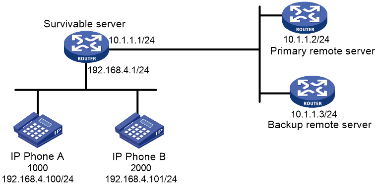
As shown in Figure 7, the primary remote server processes calls between IP phone A and IP phone B. T backup remote server takes over when the primary remote server is down.
Configure the keepalive feature for the survivable server to take over when both remote servers are down.
Procedure
1. Configure the SIP registrar feature on the survivable server and the remote servers. For more information, see "Example: Configuring the SIP registrar."
2. Configure the keepalive feature:
# In register pool 1, specify the master and backup remote servers and enable the keepalive feature.
[Survivable-voice-register-pool1] proxy ip 10.1.1.2 monitor probe sip 10.1.1.3
# Configure the parameters for the keepalive feature.
[Survivable-voice-register-pool1] voice-class sip options-keepalive up-interval 100 down-interval 50 retry 3
# In register pool 2, specify the master and backup remote servers and enable the keepalive feature.
[Survivable-voice-register-pool2] proxy ip 10.1.1.2 monitor probe sip 10.1.1.3
# Configure the parameters for the keepalive feature.
[Survivable-voice-register-pool2] voice-class sip options-keepalive up-interval 100 down-interval 50 retry 3
[Survivable-voice-register-pool2] quit
Verifying the configuration
# Display information about dynamic VoIP entities in register pools on the survivable server.
[Survivable] display voice register entity all
Entities created dynamically on register pool 1:
entity 40001 voip
match-template 1000$
address sip ip 192.168.4.100 port 10002
session transport udp
priority 1
entity 40002 voip
match-template 1000$
address sip ip 10.1.1.2 port 5060: VoIP entity available
session transport global
Entities created dynamically on register pool 2:
entity 40003 voip
match-template 2000$
address sip ip 192.168.4.101 port 10003
session transport udp
priority 3
entity 40004 voip
match-template 2000$
address sip ip 10.1.1.2 port 5060: VoIP entity available
session transport global
The output shows that the remote server is available.
Example: Configuring PSTN backup
Network configuration
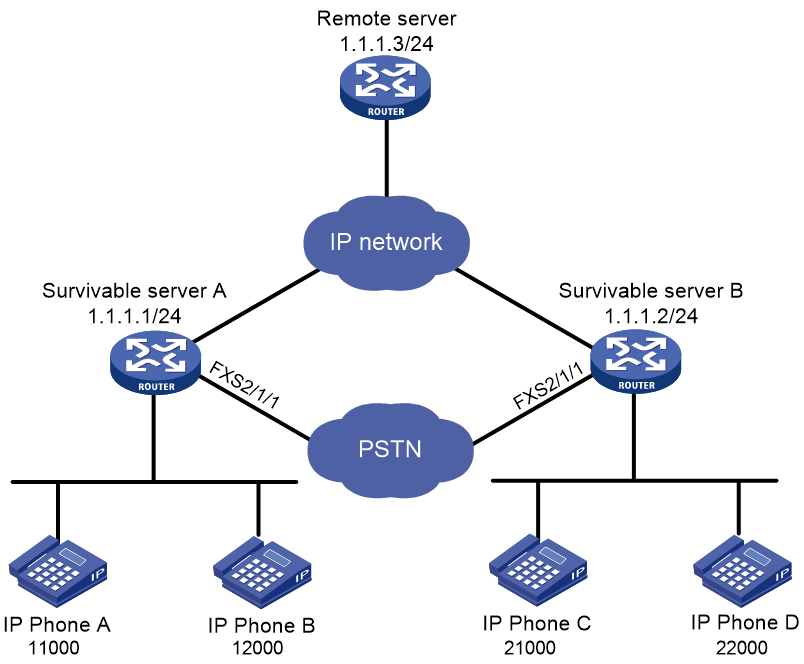
As shown in Figure 8, the remote server processes calls between all IP phones.
Configure POTS entities on the survivable servers, so IP phones can call each other over the PSTN network when the remote server is not accessible.

Procedure
1. Configure the SIP registrar feature on the survivable servers and the remote server. For more information, see "Example: Configuring the SIP registrar."
2. Configure POTS entities:
# On Survivable server A, create POTS entity 2, and bind FXS interface line 2/1/1 to POTS entity 2.
[SurvivableA] voice-setup
[SurvivableA-voice] dial-program
[SurvivableA-voice-dial] entity 2 pots
[SurvivableA-voice-dial-entity2] line 2/1/1
# Configure the number template as 2…. for POTS entity 2, and set the priority of the POTS entity to 5.
[SurvivableA-voice-dial-entity2] match-template 2....
[SurvivableA-voice-dial-entity2] priority 5
# On Survivable server B, create POTS entity 1, and bind FXS interface line 2/1/1 to POTS entity 1.
[SurvivableB] voice-setup
[SurvivableB-voice] dial-program
[SurvivableB-voice-dial] entity 1 pots
[SurvivableB-voice-dial-entity1] line 2/1/1
# Configure the number template as 1…. for POTS entity 1, and set the priority of the POTS entity to 5.
[SurvivableB-voice-dial-entity1] match-template 1....
[SurvivableB-voice-dial-entity1] priority 5
Verifying the configuration
# Verify that IP phone A and IP phone C can call each other when the remote server is not accessible. (Details not shown.)
Example: Configuring basic call services
Network configuration
As shown in Figure 9, the remote server processes calls between all IP phones.
Configure the survivable servers and the remote server to meet the following requirements:
· IP phones within a branch can call each other.
· IP phones in different branches can call each other.
· All IP phones can call each other when the remote server is not accessible.
Procedure
1. Configure the SIP registrar feature on the survivable servers and the remote server. For more information, see "Example: Configuring the SIP registrar."
2. Configure the remote server:
# Create VoIP entity 10, configure the call destination IP address as 1.1.1.1, and configure the number template as 1.T.
<Remote> system-view
[Remote] voice-setup
[Remote-voice] dial-program
[Remote-voice-dial] entity 10 voip
[Remote-voice-dial-entity10] address sip ip 1.1.1.1
[Remote-voice-dial-entity10] match-template 1.T
[Remote-voice-dial-entity10] quit
# Create VoIP entity 11, configure the call destination IP address as 1.1.1.2, and configure the number template as 2.T.
[Remote-voice-dial] entity 11 voip
[Remote-voice-dial-entity11] address sip ip 1.1.1.2
[Remote-voice-dial-entity11] match-template 2.T
3. Configure Survivable server A:
# Create VoIP entity 10, configure the call destination IP address as 1.1.1.3, and configure the number template as .T.
<SurvivableA> system-view
[SurvivableA] voice-setup
[SurvivableA-voice] dial-program
[SurvivableA-voice-dial] entity 10 voip
[SurvivableA-voice-dial-entity10] address sip ip 1.1.1.3
[SurvivableA-voice-dial-entity10] match-template .T
# Enable the keepalive function for VoIP entity 11.
[SurvivableA-voice-dial-entity10] voice-class sip options-keepalive
[SurvivableA-voice-dial-entity10] quit
4. Configure Survivable server B:
# Create VoIP entity 11, configure the call destination IP address as 1.1.1.3, and configure the number template as .T.
<SurvivableB> system-view
[SurvivableB] voice-setup
[SurvivableB-voice] dial-program
[SurvivableB-voice-dial] entity 11 voip
[SurvivableB-voice-dial-entity11] address sip ip 1.1.1.3
[SurvivableB-voice-dial-entity11] match-template .T
# Enable the keepalive function for VoIP entity 11.
[SurvivableB-voice-dial-entity11] voice-class sip options-keepalive
5. Configure PSTN backup.
For more information, see "Example: Configuring PSTN backup."
Verifying the configuration
# Verify that IP phone A and IP phone B can call each other and that IP phone C and D can call each other. (Details not shown.)
# Verify that IP phone A and IP phone C can call each other and that IP phone B and D can call each other. (Details not shown.)
# Verify that IP phone A and IP phone C can call each other when the remote server is down. (Details not shown.)
Example: Configuring MOH
Network configuration
As shown in Figure 10, the call management server in the headquarters processes calls between IP phones in the two branches.
Configure MOH on Survivable server A and Survivable server B.
Procedure
1. Configure the SIP registrar feature on Survivable server A and Survivable server B. For more information, see "Example: Configuring the SIP registrar."
2. Save the media files g711u1.wav and g711u2.wav to the storage media on Survivable server A and Survivable server B, respectively. (Details not shown.)
3. Configure Survivable server A:
# Enable SIP-to-SIP calling.
<SurvivableA> system-view
[SurvivableA] voice-setup
[SurvivableA-voice] allow-connections sip to sip
# Specify the g711u1.wav file as the MOH resource file, and configure the MOH multicast address as 239.1.1.2 with port 2008 and outgoing interface 1.1.1.1.
[SurvivableA-voice] voice register global
[SurvivableA-voice-register-global] moh file g711u1.wav
[SurvivableA-voice-register-global] multicast moh ip 239.1.1.1 port 2008 route 1.1.1.1
4. Configure Survivable server B:
# Enable SIP-to-SIP calling.
<SurvivableB> system-view
[SurvivableB] voice-setup
[SurvivableB-voice] allow-connections sip to sip
# Specify the g711u2.wav file as the MOH resource file, and configure the MOH multicast address as 239.1.1.2 with port 2009 and outgoing interface 1.1.1.2.
[SurvivableB-voice] voice register global
[SurvivableB-voice-register-global] moh file g711u2.wav
[SurvivableB-voice-register-global] multicast moh ip 239.1.1.2 port 2009 route 1.1.1.2
5. On the call management server, configure the MOH multicast address for each branch. (Details not shown.)
Verifying the configuration
# Verify that IP phone B held by IP phone A can hear the music of the file g711u2.wav. (Details not shown.)
# Verify that IP phone A held by IP phone B can hear the music of the file g711u1.wav. (Details not shown.)
Example: Configuring MWI
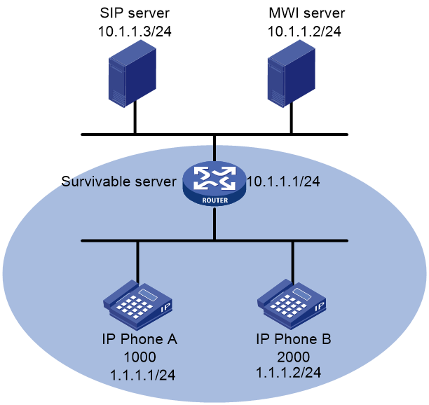
Network requirement
As shown in Figure 11, the SIP server processes calls between IP phone A and IP phone B. IP phone A and IP phone B subscribe to the MWI service.
Configure MWI on the survivable server so that IP phone A and IP phone B can receive MWI messages when the SIP server is down.
Procedure
1. Configure the SIP registrar feature on the survivable server. For more information, see "Example: Configuring the SIP registrar."
2. Configure MWI on the survivable server:
# Specify a voice mail server with the IP address 10.1.1.2.
<Server> system-view
[Server] voice-setup
[Server-voice] sip
[Server-voice-sip] mwi-server ip 10.1.1.2
[Server-voice-sip] quit
# Enable MWI for DN 1 and DN 2.
[Server-voice] voice register dn 1
[Server-voice-register-dn1] mwi
[Server-voice-register-dn1] quit
[Server-voice] voice register dn 2
[Server-voice-register-dn2] mwi
[Server-voice-register-dn2] return
Verifying the configuration
# Display the subscription states for phone numbers on the survivable server.
<Server> display voice sip subscribe-state
Number Server Address Expires Status
--------------------------------------------------------------------------
1000 10.1.1.1:5060 2285 Online
2000 10.1.1.1:5060 2326 Online
The output shows that IP phone A and IP phone B have successfully subscribed to the MWI service.
# Display MWI information for phone numbers that have a subscription on the survivable server.
<Server> display voice mwi all
Message Waiting Indication Information:
---------------------------------------------------------------------
MWI type: Solicited
MWI server: 10.1.1.2 port: 5060
MWI expires: 3600
---------------------------------------------------------------------
Number: 1000
Messages-Waiting: Yes
Voicemail: 3/0 (0/0)
Total: 3(0)
---------------------------------------------------------------------
Number: 2000
Messages-Waiting: No
Total: 0(0)
Example: Configuring call pickup
Network configuration
As shown in Figure 12, the remote server processes calls between the IP phones.
Configure call pickup on the remote server so that IP phone C can answer calls for IP phone A.

Procedure
1. Configure the SIP registrar feature on the remote server. For more information, see "Example: Configuring the SIP registrar."
2. Configure call pickup:
¡ Configure direct call pickup.
No action is required.
¡ Configure local group pickup:
# Create DN 1, assign DN 1 to pickup group 1, and configure the register number template as 1000$ for the DN.
<Server> system-view
[Server] voice-setup
[Server-voice] voice register dn 1
[Server-voice-register-dn1] pickup-group 1
[Server-voice-register-dn1] number 1000$
[Server-voice-register-dn1] quit
# Create DN 3, assign DN 3 to pickup group 1, and configure the register number template as 3000$ for the DN.
[Server-voice] voice register dn 3
[Server-voice-register-dn3] pickup-group 1
[Server-voice-register-dn3] number 3000$
¡ Configure group pickup.
# Create DN 1, and configure the register number template as 1000$ for the DN.
<Server> system-view
[Server] voice-setup
[Server-voice] voice register dn 1
[Server-voice-register-dn1] number 1000$
# Assign DN 1 to pickup group 1.
[Server-voice-register-dn1] pickup-group 1
Verifying the configuration
· Verify that IP phone C can directly pick up calls for IP phone A.
# Place a call from IP phone B to IP phone A. (Details not shown.)
# When IP phone A rings, press the GPickUp softkey and dial 1000 on IP phone C. The call is established between IP phone C and IP phone A. (Details not shown.)
· Verify that IP phone C can pick up calls for IP phone A in the same pickup group.
# Place a call from IP phone B to IP phone A. (Details not shown.)
# When IP phone A rings, press the PickUp softkey or the GPickUp softkey plus the asterisk (*) key on IP phone C. The call is established between IP phone C and IP phone A. (Details not shown.)
· Verify that IP phone C can pick up calls for IP phone A in a different pickup group.
# Place a call from IP phone B to IP phone A. (Details not shown.)
# When IP phone A rings, press the GPickUp softkey and dial 1 on IP phone C. The call is established between IP phone C and IP phone A. (Details not shown.)
Example: Configuring DND
Network configuration
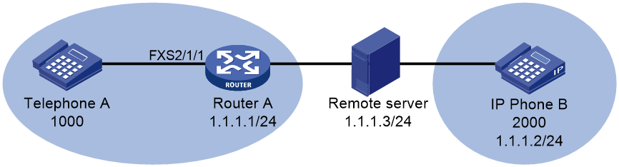
As shown in Figure 13, Router A is a SIP gateway. The remote server processes calls between Telephone A and IP phone B.
Configure DND for Telephone A on the remote server.
Procedure
1. Configure the remote server:
# Enable SIP-to-SIP calling.
<Server> system-view
[Server] voice-setup
[Server-voice] allow-connections sip to sip
# Specify the remote mode.
[Server-voice] voice register global
[Server-voice-register-global] mode alone
[Server-voice-register-global] quit
# Enable the SIP registrar.
[Server-voice] sip
[Server-voice-sip] registrar server
[Server-voice-sip] quit
# Create register pool 1, permit Telephone A with number 1000 and IP address 1.1.1.1 to register, and enable DND.
[Server-voice] voice register pool 1
[Server-voice-register-pool1] number 1 1000$
[Server-voice-register-pool1] id ip 1.1.1.1
[Server-voice-register-pool1] dnd
[Server-voice-register-pool1] quit
# Create register pool 2, and permit IP phone B with number 2000 and IP address 1.1.1.2 to register.
[Server-voice] voice register pool 2
[Server-voice-register-pool2] number 1 2000$
[Server-voice-register-pool2] id ip 1.1.1.2
[Server-voice-register-pool2] quit
2. Configure Router A:
# Specify a registrar with IP address 1.1.1.3.
<RouterA> system-view
[RouterA] voice-setup
[RouterA-voice] sip
[RouterA-voice-sip] registrar 1 ip 1.1.1.3
[RouterA-voice-sip] quit
# Create POTS entity 1, bind FXS interface line 2/1/1 to POTS entity 1, and configure the number template as 1000 for POTS entity 1.
[RouterA-voice] dial-program
[RouterA-voice-dial] entity 1 pots
[RouterA-voice-dial-entity1] line 2/1/1
[RouterA-voice-dial-entity1] match-template 1000$
Verifying the configuration
# Verify that you hear busy tones when you place a call from IP phone B to Telephone A. (Details not shown.)
# Verify that you hear ring back tones when you place a call from Telephone A to IP phone B. (Details not shown.)
Example: Configuring call forwarding
Network configuration
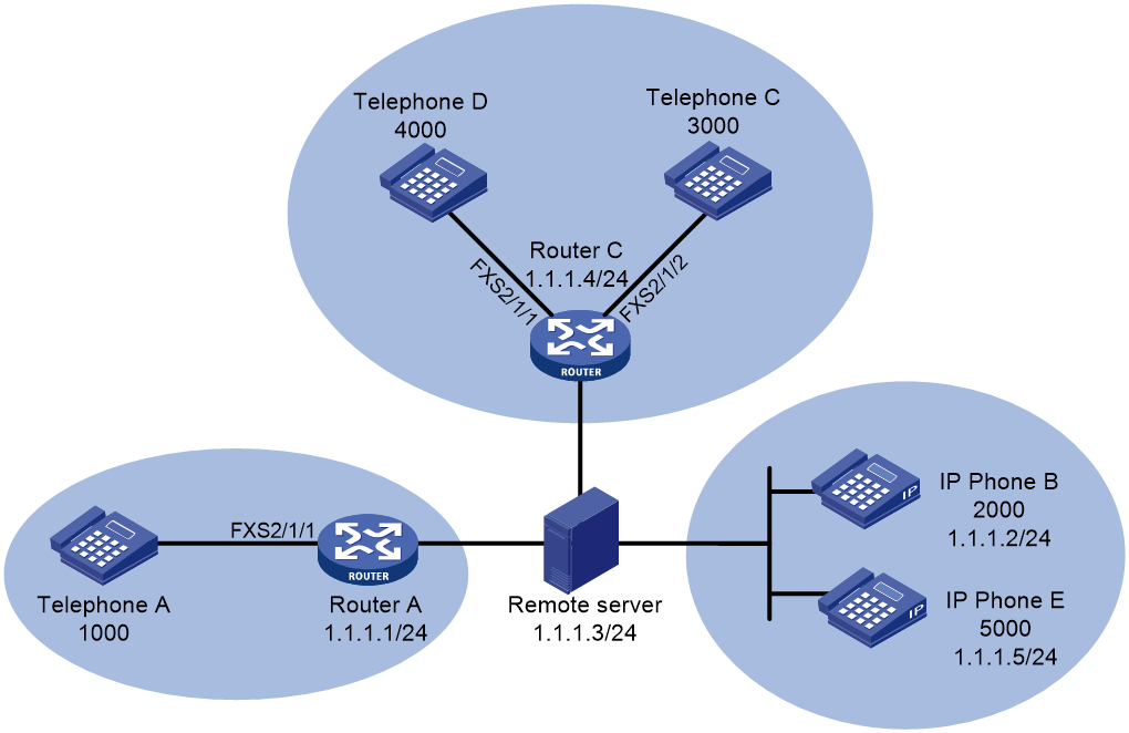
As shown in Figure 14, Router A and Router C are voice gateways. The remote server processes calls between all IP phones and telephones.
Configure call forwarding on the devices to meet the following requirements:
· Incoming calls for IP phone B will be unconditionally forwarded to Telephone C.
· Incoming calls for Telephone D will be forwarded to IP phone E if Telephone D fails to register with the remote server.
Procedure
1. Configure the remote server:
# Enable SIP-to-SIP calling.
<Server> system-view
[Server] voice-setup
[Server-voice] allow-connections sip to sip
# Specify the remote mode.
[Server-voice] voice register global
[Server-voice-register-global] mode alone
[Server-voice-register-global] quit
# Enable the SIP registrar.
[Server-voice] sip
[Server-voice-sip] registrar server
[Server-voice-sip] quit
# Create register pool 1, and permit Telephone A with number 1000 and IP address 1.1.1.1 to register.
[Server-voice] voice register pool 1
[Server-voice-register-pool1] number 1 1000$
[Server-voice-register-pool1] id ip 1.1.1.1
[Server-voice-register-pool1] quit
# Create register pool 2, and permit Telephone B with number 2000 and IP address 1.1.1.2 to register.
[Server-voice] voice register pool 2
[Server-voice-register-pool2] number 1 2000$
[Server-voice-register-pool2] id ip 1.1.1.2
# Enable call forwarding unconditional and set the forward-to number to 3000.
[Server-voice-register-pool2] call-forward b2bua all 3000
[Server-voice-register-pool2] quit
# Create register pool 3, and permit Telephone C with number 3000 and IP address 1.1.1.4 to register.
[Server-voice] voice register pool 3
[Server-voice-register-pool3] number 1 3000$
[Server-voice-register-pool3] id ip 1.1.1.4
[Server-voice-register-pool3] quit
# Create register pool 4, and permit Telephone E with number 5000 and IP address 1.1.1.5 to register.
[Server-voice] voice register pool 4
[Server-voice-register-pool4] number 1 5000$
[Server-voice-register-pool4] id ip 1.1.1.5
[Server-voice-register-pool4] quit
# Create DN 1, permit number 4000 to register, enable call forwarding unregistered, and set the forward-to number to 5000.
[Server-voice] voice register dn 1
[Server-voice-register-dn1] number 4000$
[Server-voice-register-dn1] call-forward b2bua unregistered 5000
2. Configure Router A:
# Specify a registrar with IP address 1.1.1.3.
<RouterA> system-view
[RouterA] voice-setup
[RouterA-voice] sip
[RouterA-voice-sip] registrar 1 ip 1.1.1.3
[RouterA-voice-sip] quit
# Create POTS entity 1, bind FXS interface line 2/1/1 to the entity, and configure the number template as 1000 for the entity.
[RouterA-voice] dial-program
[RouterA-voice-dial] entity 1 pots
[RouterA-voice-dial-entity1] line 2/1/1
[RouterA-voice-dial-entity1] match-template 1000$
3. Configure Router C:
# Specify a registrar with IP address 1.1.1.3.
<RouterC> system-view
[RouterC] voice-setup
[RouterC-voice] sip
[RouterC-voice-sip] registrar 1 ip 1.1.1.3
[RouterC-voice-sip] quit
# Create POTS entity 1, bind FXS interface line 2/1/2 to the entity, and configure the number template as 3000 for the entity.
[RouterC-voice] dial-program
[RouterC-voice-dial] entity 1 pots
[RouterC-voice-dial-entity1] line 2/1/2
[RouterC-voice-dial-entity1] match-template 3000$
[RouterC-voice-dial-entity1] quit
# Create POTS entity 2, and bind FXS interface line 2/1/1 to the entity.
[RouterC-voice-dial] entity 2 pots
[RouterC-voice-dial-entity2] line 2/1/1
# Configure the number template as 4000 for POTS entity 2, and configure POTS entity 2 to deregister the phone number 4000 from the registrar.
[RouterC-voice-dial-entity2] match-template 4000$
[RouterC-voice-dial-entity2] undo register-number
Verifying the configuration
# Verify that Telephone C rings when you place a call from Telephone A to IP phone B. (Details not shown.)
# Verify that Telephone E rings when you place a call from Telephone A to Telephone D. (Details not shown.)
Example: Configuring call blocking
Network configuration
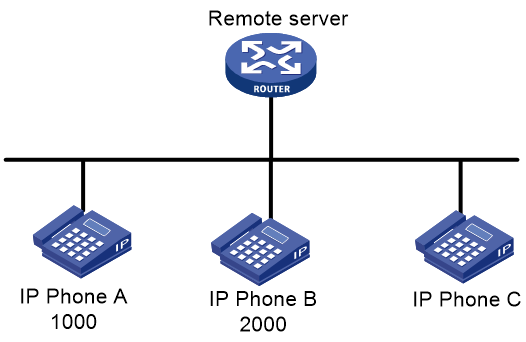
As shown in Figure 15, the remote server processes calls between IP phones.
Configure call blocking on the remote server so calls for IP phone B will be blocked on Sunday.
Procedure
1. Configure the SIP registrar feature on the remote server. For more information, see "Example: Configuring the SIP registrar."
2. Configure call blocking:
# Block calls from numbers 1000 and 2000 for 24 hours on Sunday.
<Server> system-view
[Server] voice-setup
[Server-voice] after-hours block pattern 1 1000$
[Server-voice] after-hours block pattern 2 2000$
[Server-voice] after-hours day Sun 00:00 23:59
# Create DN 1, and exempt number 1000 from call blocking.
[Server-voice] voice register dn 1
[Server-voice-register-dn1] after-hours exempt
[Server-voice-register-dn1] number 1000$
# Apply the DN to the register pool where dynamic VoIP entities for IP phone A are created. (Details not shown.)
Verifying the configuration
# Verify that you hear busy tones when you place a call from IP phone C to IP phone B on Sunday. (Details not shown.)
# Verify that you hear ring back tones when you place a call from IP phone C to IP phone A on Sunday. (Details not shown.)
Example: Configuring FACs on a gateway
Network configuration
As shown in Figure 16, Router A is a voice gateway. Configure FACs on Router A so that incoming calls for Telephone A are forwarded to Telephone B.

Procedure
· (Method 1) Configure standard FACs.
<RouterA> system-view
[RouterA] voice-setup
[RouterA-voice] fac standard
· (Method 2) Configure custom FACs.
<RouterA> system-view
[RouterA] voice-setup
[RouterA-voice] fac custom callfwd busy 123
[RouterA-voice] fac custom callfwd busy-cancel 456
[RouterA-voice] fac terminator 7
Verifying the configuration
· Verify that standard FACs for the call forwarding service are correctly configured.
# Dial *57*, and then dial 2000 on Telephone A. You will hear three beeps, which means the call forwarding service is successfully activated. (Details not shown.)
# Dial #57# on Telephone A. You will hear three beeps, which means the call forwarding service is successfully deactivated. (Details not shown.)
· Verify that custom FACs for the call forwarding service are correctly configured.
# Dial 12320007 on Telephone A. You will hear three beeps, which means the call forwarding service is successfully activated. (Details not shown.)
# Dial 456 on Telephone A to deactivate the call forwarding busy service. (Details not shown.)
Example: Configuring FACs for the call forwarding service on a voice server
Network configuration
As shown in Figure 17, Router A and Router B are voice gateways. Telephone A, IP phone B, and Telephone C have registered with the remote server. The remote server processes calls between the phones.
Configure standard FACs on the remote server to activate the call forwarding service on Telephone A.

Procedure
1. Configure the remote server:
# Specify the remote mode.
<Server> system-view
[Server] voice-setup
[Server-voice] allow-connections sip to sip
[Server-voice] voice register global
[Server-voice-register-global] mode alone
[Server-voice-register-global] quit
# Enable the SIP registrar.
[Server-voice] sip
[Server-voice-sip] registrar server
[Server-voice-sip] quit
# Enable standard FACs.
[Server-voice] fac standard
# Create register pool 1, and permit Telephone A with number 1000 and IP address 1.1.1.1 to register.
[Server-voice] voice register pool 1
[Server-voice-register-pool1] number 1 1000$
[Server-voice-register-pool1] id ip 1.1.1.1
[Server-voice-register-pool1] quit
# Create register pool 2, and permit Telephone B with number 2000 and IP address 1.1.1.2 to register.
[Server-voice] voice register pool 2
[Server-voice-register-pool2] number 1 2000$
[Server-voice-register-pool2] id ip 1.1.1.2
[Server-voice-register-pool2] quit
# Create register pool 3, and permit Telephone C with number 3000 and IP address 1.1.1.4 to register.
[Server-voice] voice register pool 3
[Server-voice-register-pool3] number 1 3000$
[Server-voice-register-pool3] id ip 1.1.1.4
[Server-voice-register-pool3] quit
2. Configure Router A:
# Specify a registrar with IP address 1.1.1.3.
<RouterA> system-view
[RouterA] voice-setup
[RouterA-voice] sip
[RouterA-voice-sip] registrar 1 ip 1.1.1.3
[RouterA-voice-sip] quit
# Create POTS entity 1, bind FXS interface line 2/1/1 to the entity, and configure the number template as 1000 for the entity.
[RouterA-voice] dial-program
[RouterA-voice-dial] entity 1 pots
[RouterA-voice-dial-entity1] line 2/1/1
[RouterA-voice-dial-entity1] match-template 1000
[RouterA-voice-dial-entity1] quit
# Create VoIP entity 2, configure the number template as *40*1234, and call destination as 1.1.1.3 for the entity.
[RouterA-voice-dial] entity 2 voip
[RouterA-voice-dial-entity2] match-template *40*1234
[RouterA-voice-dial-entity2] address sip ip 1.1.1.3
Verifying the configuration
# Dial *40*1234 on Telephone A. You will hear three beeps, which means the call forwarding service is activated. (Details not shown.)
Example: Configuring FACs for the call pickup service on a voice server
Network configuration
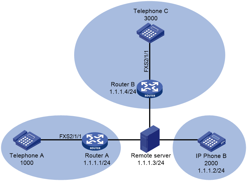
As shown in Figure 18, Router A and Router B are voice gateways. Telephone A, IP phone B, and Telephone C have registered with the remote server. The remote server processes calls between the phones.
Configure standard FACs on the remote server to activate direct call pickup on Telephone C.
Procedure
1. Configure the remote server:
# Specify the remote mode.
<Server> system-view
[Server] voice-setup
[Server-voice] allow-connections sip to sip
[Server-voice] voice register global
[Server-voice-register-global] mode alone
[Server-voice-register-global] quit
# Enable the SIP registrar.
[Server-voice] sip
[Server-voice-sip] registrar server
[Server-voice-sip] quit
# Enable standard FACs.
[Server-voice] fac standard
# Create register pool 1, and permit Telephone A with number 1000 and IP address 1.1.1.1 to register.
[Server-voice] voice register pool 1
[Server-voice-register-pool1] number 1 1000$
[Server-voice-register-pool1] id ip 1.1.1.1
[Server-voice-register-pool1] quit
# Create register pool 2, and permit Telephone B with number 2000 and IP address 1.1.1.2 to register.
[Server-voice] voice register pool 2
[Server-voice-register-pool2] number 1 2000$
[Server-voice-register-pool2] id ip 1.1.1.2
[Server-voice-register-pool2] quit
# Create register pool 3, and permit Telephone C with number 3000 and IP address 1.1.1.4 to register.
[Server-voice] voice register pool 3
[Server-voice-register-pool3] number 1 3000$
[Server-voice-register-pool3] id ip 1.1.1.4
[Server-voice-register-pool3] quit
2. Configure Router A:
# Specify a registrar with IP address 1.1.1.3.
<RouterA> system-view
[RouterA] voice-setup
[RouterA-voice] sip
[RouterA-voice-sip] registrar 1 ip 1.1.1.3
[RouterA-voice-sip] quit
# Create POTS entity 1, bind FXS interface line 2/1/1 to the entity, and configure the number template as 1000 for the entity.
[RouterA-voice] dial-program
[RouterA-voice-dial] entity 1 pots
[RouterA-voice-dial-entity1] line 2/1/1
[RouterA-voice-dial-entity1] match-template 1000
[RouterA-voice-dial-entity1] quit
# Create VoIP entity 2, configure the number template as 3000, and call destination as 1.1.1.3 for the entity.
[RouterA-voice-dial] entity 2 voip
[RouterA-voice-dial-entity2] match-template *40*1234
[RouterA-voice-dial-entity2] address sip ip 1.1.1.3
3. Configure Router B:
# Specify a registrar with IP address 1.1.1.3.
<RouterB> system-view
[RouterB] voice-setup
[RouterB-voice] sip
[RouterB-voice-sip] registrar 1 ip 1.1.1.3
[RouterB-voice-sip] quit
# Create POTS entity 1, bind FXS interface line 2/1/1 to the entity, and configure the number template as 3000 for the entity.
[RouterB-voice] dial-program
[RouterB-voice-dial] entity 1 pots
[RouterB-voice-dial-entity1] line 2/1/1
[RouterB-voice-dial-entity1] match-template 3000
[RouterB-voice-dial-entity1] quit
Verifying the configuration
# Verify that you can answer the call for Telephone C on Telephone B by dialing *80*3000. (Details not shown.)