- Table of Contents
- Related Documents
-
| Title | Size | Download |
|---|---|---|
| 08-Customizable IVR configuration | 332.80 KB |
Contents
Restrictions: Hardware compatibility with customizable IVR
Restrictions: Licensing requirements for customizable IVR
Customizable IVR tasks at a glance
Specifying an ID for a media file
Configuring global policies for handling input errors and timeouts
Restrictions and guidelines for IVR node configuration
Display and maintenance commands for customizable IVR
Customizable IVR configuration examples
Example: Configuring call node-based normal secondary calls by using dial terminator match
Example: Configuring call node-based normal secondary calls by using number length match
Example: Configuring call node-based normal secondary calls by using number match
Example: Configuring call node-based extension secondary calls
Example: Configuring jump nodes
Example: Configuring service node-based immediate secondary calls
Example: Configuring service node-based call ending
Example: Configuring comprehensive IVR nodes
Node depth exceeds eight levels
Configuring customizable IVR
About customizable IVR
Interactive voice response (IVR) is extensively used in voice communications. The IVR system enables you to customize interactive operations and humanize other services. If a subscriber dials an IVR access number, the IVR system plays the prerecorded voice prompts to direct the subscriber about how to proceed.
Customizable items for IVR
A conventional interactive voice system uses fixed media files and operations. IVR enables you to customize your own interactive system by adding, modifying, and removing media files. IVR has the following advantages:
· Voice prompts—You can customize voice prompts, save them as a .wav file, and upload the file to a voice device. The voice device plays the customizable voice prompts to subscribers. The adding, modifying, and removing operations in the IVR system are simple and easy to use, and the configurations take effect immediately.
· Codecs—The IVR system supports the following codecs for voice prompts:
¡ G.711alaw and G.711ulaw—Provide high voice quality but require large memory space.
¡ G.723r53 and G.729r8—Provide relatively low voice quality but require small memory space.
· Human-machine interactive process—The IVR system simplifies tasks such as configuring IVR access numbers, voice prompts, and combinations of keys and voice prompts.
· Error and timeout handling policies—The IVR system allows you to customize input error and timeout handling policies for call nodes and jump nodes. You can configure input error and timeout handling policies for a specific node or globally.
· Secondary calls—The IVR system supports the following types of secondary calls:
¡ Immediate secondary call—A subscriber makes an immediate secondary call without dialing the number of the called party. Immediate secondary calls are executed by service nodes.
¡ Normal secondary call—A subscriber makes a normal secondary call by dialing the number of the called party. Normal secondary calls are executed by call nodes. You can configure a node to match the length of a number, match the terminator, or match the number.
¡ Extension secondary call—A subscriber makes an extension secondary call by dialing the extension number of the called party. Extension secondary calls are executed by call nodes.
Types of IVR nodes
To simplify configuration, the IVR system uses nodes as basic units for configuration. You can define the following types of nodes:
· Call node—Executes a secondary call.
· Jump node—Jumps to another node according to user input. A maximum of eight successive jump operations are supported.
· Service node—Executes various operations, such as executing an immediate secondary call, jumping to another node, terminating a call, and playing a media file.
You can combine different node types to implement complex functions.
Restrictions: Hardware compatibility with customizable IVR
|
Hardware |
Customizable IVR compatibility |
|
MSR810, MSR810-W, MSR810-W-DB, MSR810-LM, MSR810-W-LM, MSR810-10-PoE, MSR810-LM-HK, MSR810-W-LM-HK, MSR810-LM-CNDE-SJK, MSR810-CNDE-SJK |
Yes |
|
MSR810-LMS, MSR810-LUS |
No |
|
MSR810-LMS-EA, MSR810-LME |
No |
|
MSR2600-6-X1 |
No |
|
MSR2600-10-X1 |
Yes |
|
MSR 2630 |
Yes |
|
MSR3600-28, MSR3600-51 |
Yes |
|
MSR3600-28-SI, MSR3600-51-SI |
No |
|
MSR3600-28-X1, MSR3600-28-X1-DP, MSR3600-51-X1, MSR3600-51-X1-DP |
No |
|
MSR3610-I-DP, MSR3610-IE-DP, MSR3610-IE-ES, MSR3610-IE-EAD |
No |
|
MSR3610-X1, MSR3610-X1-DP, MSR3610-X1-DC, MSR3610-X1-DP-DC |
Yes |
|
MSR 3610, MSR 3620, MSR 3620-DP, MSR 3640, MSR 3660 |
Yes |
|
MSR3610-G, MSR3620-G |
No |
|
Hardware |
Customizable IVR compatibility |
|
MSR810-W-WiNet, MSR810-LM-WiNet |
No |
|
MSR830-4LM-WiNet |
No |
|
MSR830-5BEI-WiNet, MSR830-6EI-WiNet, MSR830-10BEI-WiNet |
No |
|
MSR830-6BHI-WiNet, MSR830-10BHI-WiNet |
No |
|
MSR2600-6-WiNet |
No |
|
MSR2600-10-X1-WiNet |
Yes |
|
MSR2630-WiNet |
Yes |
|
MSR3600-28-WiNet |
Yes |
|
MSR3610-X1-WiNet |
Yes |
|
MSR3610-WiNet, MSR3620-10-WiNet, MSR3620-DP-WiNet, MSR3620-WiNet, MSR3660-WiNet |
Yes |
|
Hardware |
Customizable IVR compatibility |
|
MSR2630-XS |
No |
|
MSR3600-28-XS |
No |
|
MSR3610-XS |
Yes |
|
MSR3620-XS |
Yes |
|
MSR3610-I-XS |
No |
|
MSR3610-IE-XS |
No |
|
Hardware |
Customizable IVR compatibility |
|
MSR810-LM-GL |
No |
|
MSR810-W-LM-GL |
No |
|
MSR830-6EI-GL |
No |
|
MSR830-10EI-GL |
No |
|
MSR830-6HI-GL |
No |
|
MSR830-10HI-GL |
No |
|
MSR2600-6-X1-GL |
No |
|
MSR3600-28-SI-GL |
No |
Restrictions: Licensing requirements for customizable IVR
To support customizable IVR, some device models require the Voice Software License. For more information, see license management in Fundamentals Configuration Guide.
Customizable IVR tasks at a glance
To configure customizable IVR, perform the following tasks:
2. Specifying an ID for a media file
3. Configuring global policies for handling input errors and timeouts
Configure one or more types of nodes as needed.
Configuring an IVR entity
Restrictions and guidelines
When you use a VoIP entity to call an IVR access number, you must configure out-of-band DTMF to transmit the DTMF tones. For information about configuring out-of-band DTMF, see "Configuring SIP."
Procedure
1. Enter system view.
system-view
2. Enter voice view.
voice-setup
3. Enter dial program view.
dial-program
4. Create an IVR entity and enter its view.
entity entity-number ivr
5. Configure the root node (the first node of the IVR entity).
ivr-root node-id
By default, no root node is configured for an IVR entity.
6. Configure a number template for the IVR entity.
match-template match-string
7. (Optional.) Configure the other functions for the IVR entity.
For information about configuring other functions for an IVR entity, see "Configuring voice entities."
Specifying an ID for a media file
About this task
You can enter the corresponding media resource management view by specifying a codec. In each media resource management view, you can specify an ID for a media file.
Procedure
1. Enter system view.
system-view
2. Enter voice view.
voice-setup
3. Enter media resource management view.
media-file { g711alaw | g711ulaw | g723r53 | g729r8 }
4. Specify an ID for a media file.
set-media media-id file filename
By default, no ID is specified for a media file.
Configuring global policies for handling input errors and timeouts
About this task
You can configure policies for handling input errors and timeouts globally for all nodes in IVR management view or for a node in node view. If you do not configure policies for a node, the global handling policies are used for the node. If you configure policies both for a node and globally, the node-specific policies take priority over the global policies.
Procedure
1. Enter system view.
system-view
2. Enter voice view.
voice-setup
3. Enter IVR management view.
ivr-system
4. Configure a global policy for handling input errors.
global-input-error { media-play media-id [ play-times ] | repeat repeat-times } *
By default, the system does not play voice prompts for input errors and terminates the call after three times of input errors.
5. Configure a global policy for handling input timeouts.
global-timeout { expires seconds | media-play media-id [ play-times ] | repeat repeat-times } *
By default, the timeout time is 10 seconds. The system does not play voice prompts for input timeouts and terminates the call after three times of input timeouts.
Configuring an IVR node
Restrictions and guidelines for IVR node configuration
Avoid the following misconfigurations:
· No operation is configured for a node.
· Several nodes form a loop. The subscriber has no other options except jumping around these nodes.
· The IVR process jumps from node to node for more than eight times.
For more information, see "Troubleshooting IVR."
Creating an IVR node
1. Enter system view.
system-view
2. Enter voice view.
voice-setup
3. Enter IVR management view.
ivr-system
4. Create an IVR node and enter its view.
node node-id [ call | jump | service ]
5. Configure a description for the node.
description string
By default, no description exists.
Configuring a call node
About this task
Call nodes support normal secondary calls and extension secondary calls. If you configure both types of secondary calls for a call node, the system places the call for the type that first matches the dialed number. If the dialed number matches both types of the secondary calls, the system places the extension secondary call.
Because a call node requires user input, configure input error and timeout handling policies for a call node. If you do not configure handling policies for a call node, the node uses global handling policies.
A timeout under a call node can be either a timeout before the first dial or after the first dial. If the timeout happens before the first dial, the system applies the input timeout handling policy. If the timeout happens after the first dial, the system applies the input error handling policy.
Procedure
1. Enter system view.
system-view
2. Enter voice view.
voice-setup
3. Enter IVR management view.
ivr-system
4. Enter call node view.
node node-id call
5. Configure a dial program for the call node. Choose one of the following tasks:
¡ Configure an extension secondary call.
input number extension extension-number
¡ Configure the number match mode for normal secondary calls.
call-normal { length number-length | matching | terminator character }
6. (Optional.) Configure a dial prefix for the call node.
dial-prefix string
By default, no dial prefix is configured for a call node.
7. (Optional.) Specify the media file to be played when the call node is waiting for user input.
media-play media-id [ play-times ] [ force ]
By default, no media file is played when a call node is waiting for user input.
8. Configure an input error handling policy for the call node.
input-error { end-call | goto-pre-node | goto-node node-id } [ media-play media-id [ play-times ] | repeat repeat-times ] *
By default, the global input error handling policy is used for a call node.
9. Configure an input timeout handling policy for the call node.
timeout { end-call | goto-pre-node | goto-node node-id } [ expires seconds | media-play media-id [ play-times ] | repeat repeat-times ] *
By default, the global input timeout handling policy is used for a call node.
Configuring a jump node
About this task
You can configure the following functions for a jump node:
· Playing a media file.
· Jumping to another node.
· Terminating a call.
Because a jump node requires user input, configure input error and timeout handling policies for a jump node. If you do not configure handling policies for a jump node, the node uses global handling policies.
Procedure
1. Enter system view.
system-view
2. Enter voice view.
voice-setup
3. Enter IVR management view.
ivr-system
4. Enter jump node view.
node node-id jump
5. Configure a jump operation for a character.
user-input character { end-call | goto-node node-id | goto-pre-node }
By default, no jump operation is configured for a character.
6. (Optional.) Specify the media file to be played when the call node is waiting for user input.
media-play media-id [ play-times ] [ force ]
By default, no media file is played when a call node is waiting for user input.
7. Configure an input error handling policy for the jump node.
input-error { end-call | goto-pre-node | goto-node node-id } [ media-play media-id [ play-times ] | repeat repeat-times ] *
By default, the global input error handling policy is used for a jump node.
8. Configure an input timeout handling policy for the jump node.
timeout { end-call | goto-pre-node | goto-node node-id } [ expires seconds | media-play media-id [ play-times ] | repeat repeat-times ] *
By default, the global input timeout handling policy is used for a jump node.
Configuring a service node
About this task
You can configure the following operations for a service node:
· Executing an immediate secondary call.
· Jumping to another node.
· Terminating a call.
· Playing a media file.
You can configure a maximum of three operations for a service node by using the operation command and specify the execution order of the operations by using the select-rule command. If you do not specify the execution order, the default execution order is 1 > 2 > 3.
Because a service node does not involve user input, you do not need to configure input error and timeout handling policies for a service node. If an executed operation is to jump to another node or to terminate a call, the remaining operations are not executed.
Procedure
1. Enter system view.
system-view
2. Enter voice view.
voice-setup
3. Enter IVR management view.
ivr-system
4. Enter service node view.
node node-id service
5. Configure an operation for the service node.
operation number { call-immediate call-number | end-call | goto-node node-id | goto-pre-node | media-play media-id [ play-times ] }
By default, no operations are configured for a service node.
6. Specify the execution order of configured operations.
select-rule 1st-operation 2nd-operation 3rd-operation
The default execution order is 1 >2 > 3.
Display and maintenance commands for customizable IVR
Execute display commands in any view.
|
Task |
Command |
|
Display playing information. |
display voice media-play |
|
Display IVR call information. |
display voice ivr call-info |
|
Display media file information. |
display voice media-source |
Customizable IVR configuration examples
Example: Configuring call node-based normal secondary calls by using dial terminator match
Network configuration
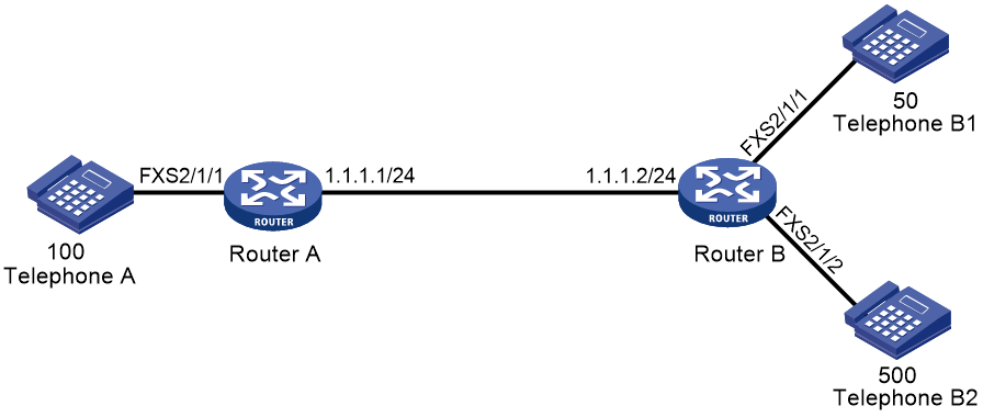
As shown in Figure 1, configure an IVR access number and customize call node functions on Router B to achieve the following purposes:
· After a subscriber originates a SIP call by dialing 300 (the IVR access number of Router B) at Telephone A, Router B plays the media file welcome.wav. Then, after the subscriber dials 50# at Telephone A to originate a secondary call, Telephone B1 rings.
· In the case of an input error, Router B plays the media file input_error.wav.
· In the case of an input timeout, Router B plays the media file timeout.wav.

Procedure
# Configure the local number as 100 for POTS entity 100, and bind FXS interface line 2/1/1 to the POTS entity.
<RouterA> system-view
[RouterA] voice-setup
[RouterA-voice] dial-program
[RouterA-voice-dial] entity 100 pots
[RouterA-voice-dial-entity100] match-template 100
[RouterA-voice-dial-entity100] line 2/1/1
[RouterA-voice-dial-entity100] quit
# Configure the called number as 300 for VoIP entity 300, and configure the destination IP address as 1.1.1.2.
[RouterA-voice-dial] entity 300 voip
[RouterA-voice-dial-entity300] match-template 300
[RouterA-voice-dial-entity300] address sip ip 1.1.1.2
[RouterA-voice-dial-entity300] outband sip
# Configure the local number as 500 for POTS entity 500, and bind FXS interface line 2/1/2 to the POTS entity.
<RouterB> system-view
[RouterB] voice-setup
[RouterB-voice] dial-program
[RouterB-voice-dial] entity 500 pots
[RouterB-voice-dial-entity500] match-template 500
[RouterB-voice-dial-entity500] line 2/1/2
[RouterB-voice-dial-entity500] quit
# Configure the local number as 50 for POTS entity 50, and bind FXS interface line 2/1/1 to the POTS entity.
[RouterB-voice-dial] entity 50 pots
[RouterB-voice-dial-entity50] match-template 50
[RouterB-voice-dial-entity50] line 2/1/1
[RouterB-voice-dial-entity50] quit
# Configure an access number of 300 for IVR entity 300, and specify node 10 as the root node.
[RouterB-voice-dial] entity 300 ivr
[RouterB-voice-dial-entity300] match-template 300
[RouterB-voice-dial-entity300] ivr-root 10
[RouterB-voice-dial-entity300] quit
[RouterB-voice-dial] quit
# Specify IDs for media files as follows:
¡ Specify ID 10001 for the media file cfa0:/wav/g729r8/welcome.wav.
¡ Specify ID 10002 for the media file cfa0:/wav/g729r8/timeout.wav.
¡ Specify ID 10003 for the media file cfa0:/wav/g729r8/input_error.wav.
[RouterB-voice] media-file g729r8
[RouterB-voice-media-g729r8] set-media 10001 file cfa0:/wav/g729r8/welcome.wav
[RouterB-voice-media-g729r8] set-media 10002 file cfa0:/wav/g729r8/timeout.wav
[RouterB-voice-media-g729r8] set-media 10003 file cfa0:/wav/g729r8/input_error.wav
[RouterB-voice-media-g729r8] quit
# Configure global policies for handling input errors and timeouts.
[RouterB-voice-ivr] global-input-error repeat 3 media-play 10003
[RouterB-voice-ivr] global-timeout repeat 4 expires 5 media-play 10002
# Configure call node 10 as follows:
¡ After the IVR access number 300 is matched, Router B plays the media file welcome.wav
¡ After the subscriber dials 50# at Telephone A, Router B originates a secondary call to Telephone B1.
[RouterB-voice-ivr] node 10 call
[RouterB-voice-ivr-node10] media-play 10001
[RouterB-voice-ivr-node10] call-normal terminator #
Verifying the configuration
# Dial the number 300 at Telephone A to verify that the media file welcome.wav is played.
# After the media file welcome.wav is played, dial 50# at Telephone A to verify that Telephone B1 rings.
Example: Configuring call node-based normal secondary calls by using number length match
Network configuration
As shown in Figure 2, configure an IVR access number and customize call node functions on Router B to achieve the following purposes:
· After a subscriber originates a call by dialing 300 (the IVR access number of Router B) at Telephone A, Router B plays the media file welcome.wav. Then, after the subscriber dials a 3-digit number 500, Telephone B2 rings.
· In the case of an input error, Router B plays the media file input_error.wav.
· In the case of an input timeout, Router B plays the media file timeout.wav.

Procedure
1. Configure Router A. For more information, see "Configure Router A:."
2. Configure Router B:
# Configure call node 10 as follows:
¡ After the IVR access number 300 is matched, Router B plays the media file welcome.wav
¡ After the subscriber dials a 3-digit number 500 at Telephone A, Router B originates a secondary call to Telephone B2.
[RouterB-voice-ivr] node 10 call
[RouterB-voice-ivr-node10] media-play 10001
[RouterB-voice-ivr-node10] call-normal length 3
# For other configurations, see "Configure Router B:."
Verifying the configuration
# Dial the number 300 at Telephone A to verify that the media file welcome.wav is played.
# After the media file welcome.wav is played, dial 500 at Telephone A to verify that Telephone B2 rings.
Example: Configuring call node-based normal secondary calls by using number match
Network configuration
As shown in Figure 3, configure an IVR access number and customize call node functions on Router B to achieve the following purposes:
· After a subscriber originates a call by dialing 300 (the IVR access number of Router B) at Telephone A, Router B plays the media file welcome.wav. Then, after the subscriber dials the phone number of Telephone B1, Telephone B1 rings.
· In the case of an input error, Router B plays the media file input_error.wav.
· In the case of an input timeout, Router B plays the media file timeout.wav.
Procedure
1. Configure Router A. For more information, see "Configure Router A:."
2. Configure Router B:
# Configure call node 10 as follows:
¡ After the IVR access number 300 is matched, Router B plays the media file welcome.wav.
¡ After the subscriber dials the number 50 at Telephone A, Router B originates a secondary call to Telephone B1.
[RouterB-voice-ivr] node 10 call
[RouterB-voice-ivr-node10] media-play 10001
[RouterB-voice-ivr-node10] call-normal matching
# For other configurations, see "Configure Router B:."
Verifying the configuration
# Dial the number 300 at Telephone A to verify that the media file welcome.wav is played.
# After the media file welcome.wav is played, dial 50 at Telephone A to verify that Telephone B1 rings.
Example: Configuring call node-based extension secondary calls
Network configuration
As shown in Figure 4, configure an IVR access number and customize call node functions on Router B to achieve the following purposes:
· After a subscriber dials 300 at Telephone A, Router B plays the media file welcome.wav. Then, after the subscriber dials 0 at Telephone A, Router B automatically originates a call to Telephone B (500).
· In the case of an input error, Router B plays the media file input_error.wav.
· In the case of an input timeout, Router B plays the media file timeout.wav.

Procedure
# Configure the local number as 100 for POTS entity 100, and bind FXS interface line 2/1/1 to the POTS entity.
<RouterA> system-view
[RouterA] voice-setup
[RouterA-voice] dial-program
[RouterA-voice-dial] entity 100 pots
[RouterA-voice-dial-entity100] match-template 100
[RouterA-voice-dial-entity100] line 2/1/1
[RouterA-voice-dial-entity100] quit
# Configure the called number as 300 for VoIP entity 300, and configure the destination IP address as 1.1.1.2.
[RouterA-voice-dial] entity 300 voip
[RouterA-voice-dial-entity300] match-template 300
[RouterA-voice-dial-entity300] address sip ip 1.1.1.2
[RouterA-voice-dial-entity300] outband sip
2. Configure Router B:
# Configure the local number as 500 for POTS entity 500, and bind FXS interface line 2/1/1 to the POTS entity.
<RouterB> system-view
[RouterB] voice-setup
[RouterB-voice] dial-program
[RouterB-voice-dial] entity 500 pots
[RouterB-voice-dial-entity500] match-template 500
[RouterB-voice-dial-entity500] line 2/1/1
[RouterB-voice-dial-entity500] quit
# Configure an access number of 300 for IVR entity 300, and specify node 10 as the root node.
[RouterB-voice-dial] entity 300 ivr
[RouterB-voice-dial-entity300] match-template 300
[RouterB-voice-dial-entity300] ivr-root 10
[RouterB-voice-dial-entity300] quit
[RouterB-voice-dial] quit
# Specify IDs for media files as follows:
¡ Specify ID 10001 for the file cfa0:/wav/g729r8/welcome.wav.
¡ Specify ID 10002 for the file cfa0:/wav/g729r8/timeout.wav.
¡ Specify ID 10003 for the file cfa0:/wav/g729r8/input_error.wav.
[RouterB-voice] media-file g729r8
[RouterB-voice-media-g729r8] set-media 10001 file cfa0:/wav/g729r8/welcome.wav
[RouterB-voice-media-g729r8] set-media 10002 file cfa0:/wav/g729r8/timeout.wav
[RouterB-voice-media-g729r8] set-media 10003 file cfa0:/wav/g729r8/input_error.wav
[RouterB-voice-media-g729r8] quit
# Configure global policies for handling input errors and timeouts.
[RouterB-voice-ivr] global-input-error repeat 3 media-play 10003
[RouterB-voice-ivr] global-timeout repeat 4 expires 5 media-play 10002
# Configure call node 10 as follows:
¡ After the IVR access number 300 is matched, Router B plays the media file welcome.wav.
¡ After the subscriber dials 0 at Telephone A, Router B automatically originates a call to Telephone B.
[RouterB-voice-ivr] node 10 call
[RouterB-voice-ivr-node10] media-play 10001
[RouterB-voice-ivr-node10] input 0 extension 500
Verifying the configuration
# Dial the number 300 at Telephone A to verify that the media file welcome.wav is played.
# After the media file welcome.wav is played, dial 0 at Telephone A to verify that Telephone B rings.
Example: Configuring jump nodes
Network configuration
As shown in Figure 5, configure an IVR access number and customize jump node functions on Router B to achieve the following purposes:
· After a subscriber dials 300 (the IVR access number of Router B) at Telephone A, Router B plays the media file welcome.wav. The subscriber performs jump operations according to the voice prompts. Then, after the subscriber presses the # key, Router B terminates the call.
· In the case of an input error, Router B plays the media file input_error.wav.
· In the case of an input timeout, Router B plays the media file timeout.wav.

Procedure
# Configure the local number as 100 for POTS entity 100, and bind FXS interface line 2/1/1 to the POTS entity.
<RouterA> system-view
[RouterA] voice-setup
[RouterA-voice] dial-program
[RouterA-voice-dial] entity 100 pots
[RouterA-voice-dial-entity100] match-template 100
[RouterA-voice-dial-entity100] line 2/1/1
[RouterA-voice-dial-entity100] quit
# Configure the called number as 300 for VoIP entity 300, and configure the destination IP address as 1.1.1.2.
[RouterA-voice-dial] entity 300 voip
[RouterA-voice-dial-entity300] match-template 300
[RouterA-voice-dial-entity300] address sip ip 1.1.1.2
[RouterA-voice-dial-entity300] outband sip
2. Configure Router B:
# Configure the local number as 500 for POTS entity 500, and bind FXS interface line 2/1/1 to the POTS entity.
<RouterB> system-view
[RouterB] voice-setup
[RouterB-voice] dial-program
[RouterB-voice-dial] entity 500 pots
[RouterB-voice-dial-entity500] match-template 500
[RouterB-voice-dial-entity500] line 2/1/1
[RouterB-voice-dial-entity500] quit
# Configure an access number of 300 for IVR entity 300, and specify node 10 as the root node.
[RouterB-voice-dial] entity 300 ivr
[RouterB-voice-dial-entity300] match-template 300
[RouterB-voice-dial-entity300] ivr-root 10
[RouterB-voice-dial-entity300] quit
[RouterB-voice-dial] quit
# Specify IDs for media files as follows:
¡ Specify ID 10001 for the file cfa0:/wav/g729r8/welcome.wav.
¡ Specify ID 10002 for the file cfa0:/wav/g729r8/timeout.wav.
¡ Specify ID 10003 for the file cfa0:/wav/g729r8/input_error.wav.
[RouterB-voice] media-file g729r8
[RouterB-voice-media-g729r8] set-media 10001 file cfa0:/wav/g729r8/welcome.wav
[RouterB-voice-media-g729r8] set-media 10002 file cfa0:/wav/g729r8/timeout.wav
[RouterB-voice-media-g729r8] set-media 10003 file cfa0:/wav/g729r8/input_error.wav
[RouterB-voice-media-g729r8] quit
# Configure global policies for handling input errors and timeouts.
[RouterB-voice-ivr] global-input-error repeat 3 media-play 10003
[RouterB-voice-ivr] global-timeout repeat 4 expires 5 media-play 10002
# Configure jump node 10 as follows:
¡ After the IVR access number 300 is matched, Router B plays the media file welcome.wav.
¡ After the subscriber presses the key # at Telephone A, Router B terminates the call.
[RouterB-voice-ivr] node 10 jump
[RouterB-voice-ivr-node10] media-play 10001
[RouterB-voice-ivr-node10] user-input # end-call
Verify the configuration
# Dial the number 300 at Telephone A to verify that the media file welcome.wav is played.
# After the media file welcome.wav is played, dial # at Telephone A to verify that the call is terminated.
Example: Configuring service node-based immediate secondary calls
Network configuration
As shown in Figure 6, configure an IVR access number and customize service node functions on Router B to achieve the following purposes:
· After a subscriber dials 300 (the IVR access number of Router B) at Telephone A, Router B places an immediate secondary call to Telephone B.
· In the case of an input error, Router B plays the media file input_error.wav.
· In the case of an input timeout, Router B plays the media file timeout.wav.

Procedure
1. Configure Router A:
# Configure the local number as 100 for POTS entity 100, and bind FXS interface line 2/1/1 to the POTS entity.
<RouterA> system-view
[RouterA] voice-setup
[RouterA-voice] dial-program
[RouterA-voice-dial] entity 100 pots
[RouterA-voice-dial-entity100] match-template 100
[RouterA-voice-dial-entity100] line 2/1/1
[RouterA-voice-dial-entity100] quit
# Configure the called number as 300 for VoIP entity 300, and configure the destination IP address as 1.1.1.2.
[RouterA-voice-dial] entity 300 voip
[RouterA-voice-dial-entity300] match-template 300
[RouterA-voice-dial-entity300] address sip ip 1.1.1.2
[RouterA-voice-dial-entity300] outband sip
2. Configure Router B:
# Configure the local number as 500 for POTS entity 500, and bind FXS interface line 2/1/1 to the POTS entity.
<RouterB> system-view
[RouterB] voice-setup
[RouterB-voice] dial-program
[RouterB-voice-dial] entity 500 pots
[RouterB-voice-dial-entity500] match-template 500
[RouterB-voice-dial-entity500] line 2/1/1
[RouterB-voice-dial-entity500] quit
# Configure an access number of 300 for IVR entity 300, and specify node 10 as the root node.
[RouterB-voice-dial] entity 300 ivr
[RouterB-voice-dial-entity300] match-template 300
[RouterB-voice-dial-entity300] ivr-root 10
[RouterB-voice-dial-entity300] quit
[RouterB-voice-dial] quit
# Specify IDs for media files as follows:
¡ Specify ID 10001 for the file cfa0:/wav/g729r8/welcome.wav.
¡ Specify ID 10002 for the file cfa0:/wav/g729r8/timeout.wav.
¡ Specify ID 10003 for the file cfa0:/wav/g729r8/input_error.wav.
[RouterB-voice] media-file g729r8
[RouterB-voice-media-g729r8] set-media 10001 file cfa0:/wav/g729r8/welcome.wav
[RouterB-voice-media-g729r8] set-media 10002 file cfa0:/wav/g729r8/timeout.wav
[RouterB-voice-media-g729r8] set-media 10003 file cfa0:/wav/g729r8/input_error.wav
[RouterB-voice-media-g729r8] quit
# Configure global policies for handling input errors and timeouts.
[RouterB-voice-ivr] global-input-error repeat 3 media-play 10003
[RouterB-voice-ivr] global-timeout repeat 4 expires 5 media-play 10002
# Configure Service node 10 execute the immediate secondary call to Telephone B (500) without playing the media file welcome.wav.
[RouterB-voice-ivr] node 10 service
[RouterB-voice-ivr-node10] operation 1 media-play 10001 1
[RouterB-voice-ivr-node10] operation 2 call-immediate 500
[RouterB-voice-ivr-node10] select-rule 2 1 3
Verifying the configuration
# Dial the number 300 at Telephone A to verify that Telephone B rings and the media file welcome.wav is not played.
Example: Configuring service node-based call ending
Network configuration
As shown in Figure 7, configure an IVR access number and customize service node functions on Router B to achieve the following purposes:
· After a subscriber dials 300 (the IVR access number of Router B) at Telephone A, Router B plays the media file bye.wav and then terminates the call.
· In the case of an input error, Router B plays the media file input_error.wav.
· In the case of an input timeout, Router B plays the media file timeout.wav.

Procedure
1. Configure Router A:
# Configure the local number as 100 for POTS entity 100, and bind FXS interface line 2/1/1 to the POTS entity.
<RouterA> system-view
[RouterA] voice-setup
[RouterA-voice] dial-program
[RouterA-voice-dial] entity 100 pots
[RouterA-voice-dial-entity100] match-template 100
[RouterA-voice-dial-entity100] line 2/1/1
[RouterA-voice-dial-entity100] quit
# Configure the called number as 300 for VoIP entity 300, and configure the destination IP address as 1.1.1.2.
[RouterA-voice-dial] entity 300 voip
[RouterA-voice-dial-entity300] match-template 300
[RouterA-voice-dial-entity300] address sip ip 1.1.1.2
[RouterA-voice-dial-entity300] outband sip
2. Configure Router B:
# Configure the local number as 500 for POTS entity 500, and bind FXS interface line 2/1/1 to the POTS entity.
<RouterB> system-view
[RouterB] voice-setup
[RouterB-voice] dial-program
[RouterB-voice-dial] entity 500 pots
[RouterB-voice-dial-entity500] match-template 500
[RouterB-voice-dial-entity500] line 2/1/1
[RouterB-voice-dial-entity500] quit
# Configure an access number of 300 for IVR entity 300, and specify node 10 as the root node.
[RouterB-voice-dial] entity 300 ivr
[RouterB-voice-dial-entity300] match-template 300
[RouterB-voice-dial-entity300] ivr-root 10
[RouterB-voice-dial-entity300] quit
[RouterB-voice-dial] quit
# Specify IDs for media files as follows:
¡ Specify ID 10002 for the file cfa0:/wav/g729r8/timeout.wav.
¡ Specify ID 10003 for the file cfa0:/wav/g729r8/input_error.wav.
¡ Specify ID 10004 for the file cfa0:/wav/g729r8/bye.wav.
[RouterB-voice] media-file g729r8
[RouterB-voice-media-g729r8] set-media 10002 file cfa0:/wav/g729r8/timeout.wav
[RouterB-voice-media-g729r8] set-media 10003 file cfa0:/wav/g729r8/input_error.wav
[RouterB-voice-media-g729r8] set-media 10004 file cfa0:/wav/g729r8/bye.wav
[RouterB-voice-media-g729r8] quit
# Configure global policies for handling input errors and timeouts.
[RouterB-voice-ivr] global-input-error repeat 3 media-play 10003
[RouterB-voice-ivr] global-timeout repeat 4 expires 5 media-play 10002
# Configure service node 10 to play the media file bye.wav and then terminate the call.
[RouterB-voice-ivr] node 10 service
[RouterB-voice-ivr-node10] operation 2 end-call
[RouterB-voice-ivr-node10] operation 3 media-play 10004 1
[RouterB-voice-ivr-node10] select-rule 3 2 1
Verifying the configuration
# Dial the number 300 at Telephone A to verify that Router B plays the media file bye.wav and then terminates the call.
Example: Configuring comprehensive IVR nodes
Network configuration
As shown in Figure 8, configure an IVR access number and customize call node, jump node and service node functions on Router B to achieve the following purposes:
· After a subscriber dials 300 (the IVR access number of Router B) at Telephone A, Router B plays the media file welcome.wav.
¡ If the subscriber presses the * key at Telephone A, the call jumps to the service node and the subscriber hears voice prompts of the media file bye.wav. Then, the service node releases the call.
¡ If the subscriber presses the # key at Telephone A, the call jumps to the call node and the subscriber hears the voice prompts of the media file call.wav. Then, if the subscriber dials 1, the call node executes an extension secondary call to Telephone B (500).

Procedure
1. Configure Router A:
# Configure the local number as 100 for POTS entity 100, and bind FXS interface line 2/1/1 to the POTS entity.
<RouterA> system-view
[RouterA] voice-setup
[RouterA-voice] dial-program
[RouterA-voice-dial] entity 100 pots
[RouterA-voice-dial-entity100] match-template 100
[RouterA-voice-dial-entity100] line 2/1/1
[RouterA-voice-dial-entity100] quit
# Configure the called number as 300 for VoIP entity 300, and configure the destination IP address as 1.1.1.2.
[RouterA-voice-dial] entity 300 voip
[RouterA-voice-dial-entity300] match-template 300
[RouterA-voice-dial-entity300] address sip ip 1.1.1.2
[RouterA-voice-dial-entity300] outband sip
2. Configure Router B:
# Configure the local number as 500 for POTS entity 500, and bind FXS interface line 2/1/1 to the POTS entity.
<RouterB> system-view
[RouterB] voice-setup
[RouterB-voice] dial-program
[RouterB-voice-dial] entity 500 pots
[RouterB-voice-dial-entity500] match-template 500
[RouterB-voice-dial-entity500] line 2/1/1
[RouterB-voice-dial-entity500] quit
[RouterB-voice-dial] quit
# Configure an access number of 300 for IVR entity 300, and specify node 1 as the root node.
[RouterB-voice-dial] entity 300 ivr
[RouterB-voice-dial-entity300] match-template 300
[RouterB-voice-dial-entity300] ivr-root 1
[RouterB-voice-dial-entity300] quit
[RouterB-voice-dial] quit
# Specify IDs for media files as follows:
¡ Specify ID 10001 for the file cfa0:/wav/g729r8/welcome.wav.
¡ Specify ID 10002 for the file cfa0:/wav/g729r8/timeout.wav.
¡ Specify ID 10003 for the file cfa0:/wav/g729r8/input_error.wav.
¡ Specify ID 10004 for the file cfa0:/wav/g729r8/bye.wav.
¡ Specify ID 10005 for the file cfa0:/wav/g729r8/call.wav.
[RouterB-voice] media-file g729r8
[RouterB-voice-media-g729r8] set-media 10001 file cfa0:/wav/g729r8/welcome.wav
[RouterB-voice-media-g729r8] set-media 10002 file cfa0:/wav/g729r8/timeout.wav
[RouterB-voice-media-g729r8] set-media 10003 file cfa0:/wav/g729r8/input_error.wav
[RouterB-voice-media-g729r8] set-media 10004 file cfa0:/wav/g729r8/bye.wav
[RouterB-voice-media-g729r8] set-media 10005 file cfa0:/wav/g729r8/call.wav
[RouterB-voice-media-g729r8] quit
# Configure global policies for handling input errors and timeouts.
[RouterB-voice-ivr] global-input-error repeat 3 media-play 10003
[RouterB-voice-ivr] global-timeout repeat 4 expires 5 media-play 10002
# Configure jump node 1 as follows:
¡ Play the media file welcome.wav after the IVR access number 300 is matched.
¡ Jump to node 20 if the subscriber presses the * key at Telephone A after the play of the media file welcome.wav ends.
¡ Jump to node 10 if the subscriber presses the # key at Telephone A after the play of the media file welcome.wav ends.
[RouterB-voice-ivr] node 1 jump
[RouterB-voice-ivr-node1] user-input # goto-node 10
[RouterB-voice-ivr-node1] user-input * goto-node 20
[RouterB-voice-ivr-node1] media-play 10001 force
[RouterB-voice-ivr-node1] quit
# Configure call node 10 as follows:
¡ First play the media file call.wav.
¡ Originate a call to number 500 if the subscriber dials 1 at Telephone A after the play of the media file call.wav ends.
[RouterB-voice-ivr] node 10 call
[RouterB-voice-ivr-node10] media-play 10005 force
[RouterB-voice-ivr-node10] input 1 extension 500
[RouterB-voice-ivr-node10] quit
# Configure service node 20 to play the media file bye.wav and then terminate the call.
[RouterB-voice-ivr] node 20 service
[RouterB-voice-ivr-node20] operation 2 media-play 10004
[RouterB-voice-ivr-node20] operation 3 end-call
[RouterB-voice-ivr-node20] select-rule 2 3 1
Verifying the configuration
# Dial the number 300 at Telephone A to verify that Router B plays the media file welcome.wav.
# After the media file welcome.wav is played, dial the * key at Telephone A to verify that the call jumps to node 20. (You hear the voice prompt of the media file bye.wav and then hear busy tones.)
# After the media file welcome.wav is played, dial the # key at Telephone A to verify that the call jumps to node 10. (You hear the voice prompt of the media file call.wav.)
# After the media file call.wav is played, dial 1 at Telephone A to verify that the node originates an extension secondary call to number 500 and Telephone B rings.
Troubleshooting IVR
Invalid node
Symptom
A subscriber dials the IVR access number 300, and the voice prompt is played. According to the voice prompt, the subscriber presses the # key to originate a secondary call, but the call is terminated. Following are the configurations:
[Sysname-voice-dial] entity 300 ivr
[Sysname-voice-dial-entity300] match-template 300
[Sysname-voice-dial-entity300] ivr-root 1
[Sysname-voice-dial-entity300] quit
[Sysname-voice-dial] quit
[Sysname-voice] ivr-system
[Sysname-voice-ivr] node 1 jump
[Sysname-voice-ivr-node1] user-input # goto-node 10
[Sysname-voice-ivr-node1] user-input * goto-node 20
[Sysname-voice-ivr-node1] media-play 10001 force
[Sysname-voice-ivr-node1] quit
[Sysname-voice-ivr] node 10 call
Analysis
After the subscriber presses the # key, the call jumps to node 10 and is terminated because node 10 does not contain any operations.
Solution
To resolve the problem:
1. Configure node 10 to play a media file.
2. Configure a number match mode for node 10 to place normal secondary calls.
3. If the problem persists, contact H3C Support.
Loopback node
Symptom
A subscriber dials the IVR access number 300 and presses the # key to jump to node 10, but the call is terminated.
Following are the configurations:
[Sysname-voice-dial] entity 300 ivr
[Sysname-voice-dial-entity300] match-template 300
[Sysname-voice-dial-entity300] ivr-root 1
[Sysname-voice-dial-entity300] quit
[Sysname-voice-dial] quit
[Sysname-voice] ivr-system
[Sysname-voice-ivr] node 1 jump
[Sysname-voice-ivr-node1] user-input # goto-node 10
[Sysname-voice-ivr-node1] quit
[Sysname-voice-ivr] node 10 service
[Sysname-voice-ivr-node10] operation 1 goto-node 11
[Sysname-voice-ivr-node10] quit
[Sysname-voice-ivr] node 11 service
[Sysname-voice-ivr-node11] operation 1 goto-node 12
[Sysname-voice-ivr-node11] quit
[Sysname-voice-ivr] node 12 service
[Sysname-voice-ivr-node12] operation 1 goto-node 10
Analysis
After the # key is pressed, the IVR process jumps to node 10, and then jumps to node 11, node 12, and jumps back to node 10 again. Node 10 is the loopback node that causes the termination of the call.
Solution
To resolve the problem:
1. Modify the configuration for node 10, such as configuring a calling operation for it.
2. If the problem persists, contact H3C Support.
Node depth exceeds eight levels
Symptom
When the IVR process jumps to node 8, the call is terminated.
Following are the configurations:
[Sysname-voice-dial] entity 300 ivr
[Sysname-voice-dial-entity300] match-template 300
[Sysname-voice-dial-entity300] ivr-root 1
[Sysname-voice-dial-entity300] quit
[Sysname-voice-dial] quit
[Sysname-voice] ivr-system
[Sysname-voice-ivr] node 1 jump
[Sysname-voice-ivr-node1] user-input # goto-node 2
[Sysname-voice-ivr-node1] quit
[Sysname-voice-ivr] node 2 jump
[Sysname-voice-ivr-node2] user-input # goto-node 3
[Sysname-voice-ivr-node2] quit
[Sysname-voice-ivr] node 3 jump
[Sysname-voice-ivr-node3] user-input # goto-node 4
[Sysname-voice-ivr-node3] quit
[Sysname-voice-ivr] node 4 jump
[Sysname-voice-ivr-node4] user-input # goto-node 5
[Sysname-voice-ivr-node4] quit
[Sysname-voice-ivr] node 5 jump
[Sysname-voice-ivr-node5] user-input # goto-node 6
[Sysname-voice-ivr-node5] quit
[Sysname-voice-ivr] node 6 jump
[Sysname-voice-ivr-node6] user-input # goto-node 7
[Sysname-voice-ivr-node6] quit
[Sysname-voice-ivr] node 7 jump
[Sysname-voice-ivr-node7] user-input # goto-node 8
[Sysname-voice-ivr-node7] quit
[Sysname-voice-ivr] node 8 jump
[Sysname-voice-ivr-node8] user-input # goto-node 9
[Sysname-voice-ivr-node8] quit
[Sysname-voice-ivr] node 9 call
[Sysname-voice-ivr-node9] extension 1 call 300
[Sysname-voice-ivr-node9] quit
Analysis
When the IVR process jumps to node 8, it has already executed eight nodes. The eight-level limit is reached, and the call is terminated.
Solution
To resolve the problem:
1. Reduce the IVR process jumps to a value less than eight.
2. If the problem persists, contact H3C Support.
Matching mistake I
Symptom
A node is configured to execute both a normal secondary call by exactly matching the called number and an extension secondary call. When the subscriber dials 1201, the node does not execute the secondary call to the number 7745231.
Following are the configurations:
[Sysname-voice-ivr] node 1 call
[Sysname-voice-ivr-node1] call-normal matching
[Sysname-voice-ivr-node1] input 1201 extension 7745231
Analysis
There are short numbers for special usage, such as 120, 110, and 114. When the subscriber dials the input number, the node executes a normal secondary call to the short number.
Solution
To resolve the problem:
1. Change the prefixes of input numbers for extension secondary calls to numbers other than special short numbers.
2. If the problem persists, contact H3C Support.
Matching mistake 2
Symptom
A node is configured to execute both a normal secondary call by matching number before the terminator # and an extension secondary call. When the subscriber dials the number 774566, the node always connects the subscriber to the number 7745231.
Following are the configurations:
[Sysname-voice-ivr] node 1 call
[Sysname-voice-ivr-node1] call-normal terminator #
[Sysname-voice-ivr-node1] input 7 extension 7745231
Analysis
When the dialed number matches both the extension secondary call and the normal secondary call, the system places the extension secondary call. When the subscriber dials the number 7, the node matches it with the extension number 7, and connects the subscriber to the number 7745231 instead of 7745666.
Solution
To resolve the problem:
1. Change the extension number 7 to *7.
2. Change the matching terminator of the normal secondary call to a character other than an asterisk (*).
3. If the problem persists, contact H3C Support.