- Table of Contents
- Related Documents
-
| Title | Size | Download |
|---|---|---|
| 05-Call services configuration | 330.41 KB |
Restrictions: Hardware compatibility with call services
Restrictions: Licensing requirements for call services
Restrictions and guidelines: Call services configuration
Configuring the call hold mode
Restrictions and guidelines for MWI
Display and maintenance commands for MWI
Call services configuration examples
Example: Configuring call waiting
Example: Configuring call forwarding
Example: Configuring call transfer
Example: Configuring call backup
Example: Configuring three-party conference
Configuring call services
About call services
Call services are extended features for voice calls.
Call waiting
Call waiting allows a called party to suspend or end the current call and switch to a new incoming call. For example, subscriber A receives a call from subscriber C while subscriber A is in conversation with subscriber B. Instead of playing busy tones to subscriber C, the system plays ringback tones to subscriber C, and plays waiting tones to subscriber A.
Subscriber A can answer the new call by using either of the following methods:
· Pressing hookflash. In this case, subscriber B is held.
· Hanging up to end the call with subscriber B. In this case, subscriber A is immediately alerted and can pick up the phone to answer the call originated by subscriber C.
Call hold
Call hold allows a called party to place the current call on hold by pressing hookflash and place a new call.
For example, when subscriber A, who is in a conversation with subscriber B, presses hookflash, subscriber B is held (in silent state or listening to waiting tones). The system plays dial tones to subscriber A, waiting for subscriber A to initiate a new call. If subscriber A does not dial any number within a period of time, the system stops playing dial tones, and subscriber A cannot initiate a new call. Subscriber A can resume the call with subscriber B by pressing hookflash again.
Call forwarding
Call forwarding allows a called party to forward a call by notifying the calling party of the forward-to number.
For example, subscriber A calls subscriber B, who is busy, and subscriber B forwards the call to subscriber C. Then, a connection is established between subscriber A and subscriber C. Subscriber B is the initiator of call forwarding, subscriber A is the recipient, and subscriber C is the final recipient.
The system supports the following types of call forwarding:
· Call forwarding unconditional—Forwards an incoming call to the predetermined destination, regardless of the state of the called party.
· Call forwarding busy—Forwards an incoming call to the predetermined destination when the called party is busy.
· Call forwarding no reply—Forwards an incoming call to the predetermined destination when the called party provides no answer within a configurable period of time.
· Call forwarding unavailable—Forwards an incoming call to the predetermined destination when the voice interface of the called party is shut down by executing the shutdown command.
Call transfer
Call transfer allows a subscriber on an active call to connect the other party to a new call.
For example, subscriber A (the originator) and subscriber B (the recipient) are in a conversation. Subscriber A presses hookflash to place the call on hold and dials another number to originate a call to subscriber C (the final recipient). After subscriber A hangs up, the call between subscriber B and subscriber C is established.
Call transfer includes the following types:
· Unattended transfer—The originator hangs up before receiving ringback tones from the final recipient.
· Half-attended transfer—The originator hangs up after receiving ringback tones from the final recipient and before speaking with the final recipient.
· Attended transfer—The originator hangs up after speaking with the final recipient.
During the call transfer process, if the recipient does not support call transfer or the final recipient is busy or provides no reply, the initiator can re-establish the original call.
Call backup
The primary link might be unavailable when the calling party initiates a call through the IP or PSTN network. In this case, if there is a backup link (PSTN link or VoIP link) to the called party, the calling party can reinitiate a call to the called party over the backup link.
MWI
Message Waiting Indication (MWI) notifies a user that there are new messages in the voice mailbox by playing an MWI tone when the user picks up the phone. This feature works with the voice mailbox function of the voice mail server, allowing users to be informed of mailbox status without performing query operations.
The process for MWI is as follows:
1. If a subscriber misses a call, the call is redirected to the voice mailbox.
2. The voice mail server sends a NOTIFY message to notify the SIP UA.
3. The SIP UA notifies the user that there is a change in mailbox status by playing an MWI tone when the user picks up the phone.
Other indication methods such as LED are not supported.
Three-party conference
The process for initiating a three-party conference is as follows:
1. In an active two-party call, one party presses hookflash as the conference initiator and dials a third party to establish a new call.
2. The conference initiator presses hookflash again and then presses 3 to start a three-party conference.
The other two parties are called conference participants.
When the conference initiator hangs up, the three-party conference is released, and all calls are disconnected. When a conference participant hangs up, the other two parties can continue their call.
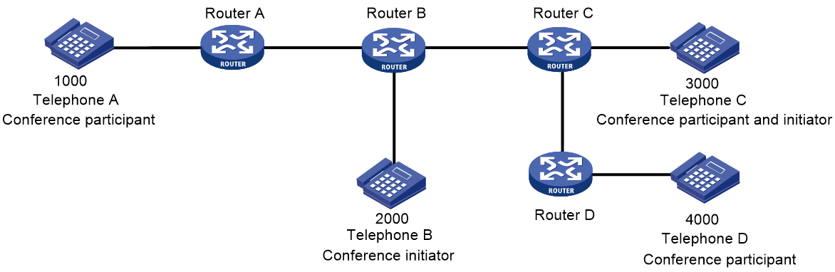
As shown in Figure 1, a three-party conference is established among Telephone A, Telephone B, and Telephone C. Telephone B is the conference initiator.
The conference initiator can switch between the three-party conference and multiparty call hold service as follows:
1. Presses hookflash and presses 2. Each party restores its state before entering the three-party conference. The call between Telephone B and Telephone A (the other party in the original active call) is held, and the call between Telephone B and Telephone C can continue.
2. Presses hookflash again and presses 3. The three parties re-enter the three-party conference.
A participant of the three-party conference can invite another party to join the conference to implement conference chaining. For example:
1. Telephone C presses hookflash and dials Telephone D.
2. Telephone D goes off-hook.
3. Telephone C presses hookflash again and presses 3.
Telephone A, Telephone B, Telephone C, and Telephone D can speak to each other. Telephone A, Telephone B, and Telephone C can be considered to be in a three-party conference, with Telephone B as the conference initiator. Telephone B, Telephone C, and Telephone D can be considered to be in a three-party conference, with Telephone C as the conference initiator.
When you implement conference chaining, follow these restrictions and guidelines:
· Make sure voice processing modules (VPMs) are installed on the devices of the conference initiators. You can use the display version command to view the installed VPMs.
· Only a conference participant that establishes a call with the initiator over IP can implement conference chaining.
Restrictions: Hardware compatibility with call services
|
Hardware |
Call service compatibility |
|
MSR810, MSR810-W, MSR810-W-DB, MSR810-LM, MSR810-W-LM, MSR810-10-PoE, MSR810-LM-HK, MSR810-W-LM-HK, MSR810-LM-CNDE-SJK, MSR810-CNDE-SJK |
Yes for only call backup |
|
MSR810-LMS, MSR810-LUS |
No |
|
MSR810-LMS-EA, MSR810-LME |
No |
|
MSR2600-6-X1 |
No |
|
MSR2600-10-X1 |
Yes |
|
MSR 2630 |
Yes |
|
MSR3600-28, MSR3600-51 |
Yes |
|
MSR3600-28-SI, MSR3600-51-SI |
No |
|
MSR3600-28-X1, MSR3600-28-X1-DP, MSR3600-51-X1, MSR3600-51-X1-DP |
No |
|
MSR3610-I-DP, MSR3610-IE-DP, MSR3610-IE-ES, MSR3610-IE-EAD |
No |
|
MSR3610-X1, MSR3610-X1-DP, MSR3610-X1-DC, MSR3610-X1-DP-DC |
Yes |
|
MSR 3610, MSR 3620, MSR 3620-DP, MSR 3640, MSR 3660 |
Yes |
|
MSR3610-G, MSR3620-G |
No |
|
Hardware |
Call service compatibility |
|
MSR810-W-WiNet, MSR810-LM-WiNet |
Yes for only call backup |
|
MSR830-4LM-WiNet |
No |
|
MSR830-5BEI-WiNet, MSR830-6EI-WiNet, MSR830-10BEI-WiNet |
No |
|
MSR830-6BHI-WiNet, MSR830-10BHI-WiNet |
No |
|
MSR2600-6-WiNet |
No |
|
MSR2600-10-X1-WiNet |
Yes |
|
MSR2630-WiNet |
Yes |
|
MSR3600-28-WiNet |
Yes |
|
MSR3610-X1-WiNet |
Yes |
|
MSR3610-WiNet, MSR3620-10-WiNet, MSR3620-DP-WiNet, MSR3620-WiNet, MSR3660-WiNet |
Yes |
|
Hardware |
Call service compatibility |
|
MSR2630-XS |
No |
|
MSR3600-28-XS |
No |
|
MSR3610-XS |
Yes |
|
MSR3620-XS |
Yes |
|
MSR3610-I-XS |
No |
|
MSR3610-IE-XS |
No |
|
Hardware |
Call service compatibility |
|
MSR810-LM-GL |
Yes for call backup |
|
MSR810-W-LM-GL |
Yes for call backup |
|
MSR830-6EI-GL |
No |
|
MSR830-10EI-GL |
No |
|
MSR830-6HI-GL |
No |
|
MSR830-10HI-GL |
No |
|
MSR2600-6-X1-GL |
No |
|
MSR3600-28-SI-GL |
No |
Restrictions: Licensing requirements for call services
To support call services, some device models require the Voice Software License. For more information, see license management in Fundamentals Configuration Guide.
Restrictions and guidelines: Call services configuration
Call waiting, call hold, call transfer, call backup, and three-party conference are always enabled on the device. You cannot use commands to enable or disable them.
You can use commands to configure call forwarding and MWI.
When you configure three-party conference, follow these restrictions and guidelines:
· Make sure voice processing modules (VPMs) are installed on the devices of the conference initiators. You can use the display version command to view the installed VPMs.
· Only a conference participant that establishes a call with the initiator over IP can implement conference chaining.
Configuring the call hold mode
About this task
Perform this task on the holding party (the initiator of call hold).
There are two call hold modes.
· Silent mode (inactive)—During call hold, the held party hears silence. This mode is configured to signal the held party to close the transmit and receive media channels of the held party.
· Unidirectional playing mode (sendonly)—During call hold, the held party hears tones or music played by a third-party music server. To play tones, configure the sendonly keyword to open its transmit media channel and close its receive media channel. To play music on hold by the third-party music server, configure the inactive keyword on the holding party and also configure the sendonly moh-number string option on the SIP trunk device. For information about configuring a SIP trunk device, see "Configuring SIP trunk."
Procedure
1. Enter system view.
system-view
2. Enter voice view.
voice-setup
3. Configure the call hold mode.
call-hold-format { inactive | sendonly [ moh-number string ] }
By default, silent mode is used for call hold.
Configuring call forwarding
Prerequisites
Before configuring call forwarding, make sure there is a route from the initiator to the final recipient.
Restrictions and guidelines
You must correctly plan forward-to numbers to avoid incorrect numbers and circular calls.
A call can be forwarded a maximum of five times.
Procedure
1. Enter system view.
system-view
2. Enter voice view.
voice-setup
3. Enter dial program view.
dial-program
4. Create a POTS entity and enter POTS entity view.
entity entity-number pots
5. Configure call forwarding.
call-forwarding { no-reply | on-busy | unavailable | unconditional } number number
By default, call forwarding is disabled.
The unconditional, unavailable, on-busy, and no-reply call forwarding types can be configured at the same time and have a descending order of priority.
Configuring MWI
About MWI
MWI includes the following types:
· Unsolicited—The SIP UA has subscribed to a voice mail server during registration and can receive NOTIFY messages from the server without sending SUBSCRIBE messages.
· Solicited—The SIP UA needs to subscribe to a voice mail server by sending SUBSCRIBE messages before it can receive NOTIFY messages from the server.
Restrictions and guidelines for MWI
If MWI is configured for one phone number in different voice entities, only the voice entity with the lowest number can successfully subscribe to the voice mail server.
Enabling MWI
1. Enter system view.
system-view
2. Enter voice interface view.
subscriber-line line-number
3. Enable MWI.
mwi
By default, MWI is disabled.
Configuring solicited MWI
1. Enter system view.
system-view
2. Enter voice view.
voice-setup
3. Enter SIP view.
sip
4. Specify the voice mail server.
mwi-server { dns domain-name | ip ip-address } [ port port-number ] [ expires seconds ] [ transport { tcp [ tls ] | udp } ] [ scheme { sip | sips } ]
By default, no voice mail server is specified.
Configuring unsolicited MWI
1. Enter system view.
system-view
2. Enter voice view.
voice-setup
3. Enter SIP view.
sip
4. Configure the voice mail server.
mwi-server { dns domain-name | ip ip-address } [ port port-number ] [ expires seconds ] [ transport { tcp [ tls ] | udp } ] [ scheme { sip | sips } ] unsolicited
By default, no voice mail server is configured.
5. Specify a registrar.
registrar registrar-index { ip ip-address | dns domain-name } [ port port-number ] [ expires seconds ] [ refresh-ratio ratio-percentage ]
Display and maintenance commands for MWI
Execute the display commands in any view.
|
Task |
Command |
|
Display MWI information for phone numbers with subscription. |
display voice mwi { all | number number } |
|
Display subscription information for phone numbers. |
display voice sip subscribe-state |
Call services configuration examples
Example: Configuring call waiting
Network configuration
As shown in Figure 2, configure call waiting so when a subscriber places a call from Telephone C to Telephone A (that is in a conversation with Telephone B), the subscriber at Telephone C hears ringback tones, and the subscriber at Telephone A hears call waiting tones.

Procedure
Before performing the following configuration, make sure Router A, Router B and Router C can reach each other.
1. Configure Router A:
# Create VoIP entity 2000, configure the destination IP address as 10.1.1.2, and configure the called number as 2000.
<RouterA> system-view
[RouterA] voice-setup
[RouterA-voice] dial-program
[RouterA-voice-dial] entity 2000 voip
[RouterA-voice-dial-entity2000] address sip ip 10.1.1.2
[RouterA-voice-dial-entity2000] match-template 2000
[RouterA-voice-dial-entity2000] quit
# Create VoIP entity 3000, configure the destination IP address as 20.1.1.2, and configure the called number as 3000.
[RouterA-voice-dial] entity 3000 voip
[RouterA-voice-dial-entity3000] address sip ip 20.1.1.2
[RouterA-voice-dial-entity3000] match-template 3000
[RouterA-voice-dial-entity3000] quit
# Configure the local number as 1000 for POTS entity 1000, and bind FXS interface line 2/1/1 to the POTS entity.
[RouterA-voice-dial] entity 1000 pots
[RouterA-voice-dial-entity1000] line 2/1/1
[RouterA-voice-dial-entity1000] match-template 1000
2. Configure Router B:
# Create VoIP entity 1000, configure the destination IP address as 10.1.1.1, and configure the called number as 1000.
<RouterB> system-view
[RouterB] voice-setup
[RouterB-voice] dial-program
[RouterB-voice-dial] entity 1000 voip
[RouterB-voice-dial-entity1000] address sip ip 10.1.1.1
[RouterB-voice-dial-entity1000] match-template 1000
[RouterB-voice-dial-entity1000] quit
# Configure the local number as 2000 for POTS entity 2000, and bind FXS interface line 2/1/1 to the POTS entity.
[RouterB-voice-dial] entity 2000 pots
[RouterB-voice-dial-entity2000] line 2/1/1
[RouterB-voice-dial-entity2000] match-template 2000
3. Configure Router C:
# Configure the local number as 3000 for POTS entity 3000, and bind FXS interface line 2/1/1 to the POTS entity.
<RouterC> system-view
[RouterC] voice-setup
[RouterC-voice] dial-program
[RouterC-voice-dial] entity 3000 pots
[RouterC-voice-dial-entity3000] line 2/1/1
[RouterC-voice-dial-entity3000] match-template 3000
[RouterC-voice-dial-entity3000] quit
# Create VoIP entity 1000, configure the destination IP address as 10.1.1.1, and configure the called number as 1000.
[RouterB-voice-dial] entity 1000 voip
[RouterB-voice-dial-entity1000] address sip ip 10.1.1.1
[RouterB-voice-dial-entity1000] match-template 1000
Verifying the configuration
Operation 1: When the subscriber at Telephone C dials 1000 to call Telephone A that is in a conversation with Telephone B, the subscriber at Telephone C hears ringback tones, and the subscriber at Telephone A hears call waiting tones. If then the subscriber at Telephone A hangs up, Telephone A rings, and the subscriber at Telephone A can pick up the phone to start a conversation with Telephone C.
Operation 2: When the subscriber at Telephone C dials 1000 to call Telephone A that is in a conversation with Telephone B, the subscriber at Telephone A can press hookflash to start a conversation with Telephone C, and Telephone B is held. The subscriber at Telephone A can press hookflash again to continue the talk with Telephone B, and then Telephone C is held.
Example: Configuring call forwarding
Network configuration
As shown in Figure 3, configure call forwarding on Router B so when a subscriber places a call from Telephone A to Telephone B:
· Router B forwards the call to Telephone C when Telephone B is busy.
· Telephone A can establish a call with Telephone C.
Procedure
Before performing the following configuration, make sure Router A, Router B and Router C can reach each other.
1. Configure Router A:
# Create VoIP entity 2000. Configure the destination IP address as 10.1.1.2, and configure the called number as 2000.
<RouterA> system-view
[RouterA] voice-setup
[RouterA-voice] dial-program
[RouterA-voice-dial] entity 2000 voip
[RouterA-voice-dial-entity2000] address sip ip 10.1.1.2
[RouterA-voice-dial-entity2000] match-template 2000
[RouterA-voice-dial-entity2000] quit
# Configure the local number as 1000 for POTS entity 1000, and bind FXS interface line 2/1/1 to the POTS entity.
[RouterA-voice-dial] entity 1000 pots
[RouterA-voice-dial-entity1000] line 2/1/1
[RouterA-voice-dial-entity1000] match-template 1000
2. Configure Router B:
# Create VoIP entity 3000. Configure the destination IP address as 20.1.1.2, and configure the number template as 3000.
<RouterB> system-view
[RouterB] voice-setup
[RouterB-voice] dial-program
[RouterB-voice-dial] entity 3000 voip
[RouterB-voice-dial-entity3000] address sip ip 20.1.1.2
[RouterB-voice-dial-entity3000] match-template 3000
[RouterB-voice-dial-entity3000] quit
# Configure the local number as 2000 for POTS entity 2000, and bind FXS interface line 2/1/1 to the POTS entity.
[RouterB-voice-dial] entity 2000 pots
[RouterB-voice-dial-entity2000] line 2/1/1
[RouterB-voice-dial-entity2000] match-template 2000
# Configure call forwarding.
[RouterB-voice-dial-entity2000] call-forwarding on-busy number 3000
3. On Router C, configure the local number as 3000 for POTS entity 3000, and bind FXS interface line 2/1/1 to the POTS entity.
<RouterC> system-view
[RouterC] voice-setup
[RouterC-voice] dial-program
[RouterC-voice-dial] entity 3000 pots
[RouterC-voice-dial-entity3000] line 2/1/1
[RouterC-voice-dial-entity3000] match-template 3000
Verifying the configuration
# When Telephone B is busy, place a call from Telephone A to Telephone B to verify that Telephone A can establish a call with Telephone C. (Details not shown.)
Example: Configuring call transfer
Network configuration
As shown in Figure 4, configure call transfer to achieve the following purpose:
When Telephone A and Telephone B are in a conversation, the subscriber at Telephone A can press hookflash to put the call on hold. Then the subscriber at Telephone A dials 3000 to call Telephone C. After the subscriber at Telephone A hangs up, Telephone B and Telephone C start a conversation.

Procedure
Before performing the following configuration, make sure Router A, Router B and Router C can reach each other.
1. Configure Router A:
# Create VoIP entity 2000. Configure the destination IP address as 10.1.1.2, and configure the called number as 2000.
<RouterA> system-view
[RouterA] voice-setup
[RouterA-voice] dial-program
[RouterA-voice-dial] entity 2000 voip
[RouterA-voice-dial-entity2000] address sip ip 10.1.1.2
[RouterA-voice-dial-entity2000] match-template 2000
[RouterA-voice-dial-entity2000] quit
# Create VoIP entity 3000. Configure the destination IP address as 20.1.1.2, and configure the called number as 3000.
[RouterA-voice-dial] entity 3000 voip
[RouterA-voice-dial-entity3000] address sip ip 20.1.1.2
[RouterA-voice-dial-entity3000] match-template 3000
[RouterA-voice-dial-entity3000] quit
# Configure the local number as 1000 for POTS entity 1000, and bind FXS interface line 2/1/1 to the POTS entity.
[RouterA-voice-dial] entity 1000 pots
[RouterA-voice-dial-entity1000] line 2/1/1
[RouterA-voice-dial-entity1000] match-template 1000
2. On Router B, configure the local number as 2000 for POTS entity 2000, and bind FXS interface line 2/1/1 to the POTS entity.
<RouterB> system-view
[RouterB] voice-setup
[RouterB-voice] dial-program
[RouterB-voice-dial] entity 2000 pots
[RouterB-voice-dial-entity2000] line 2/1/1
[RouterB-voice-dial-entity2000] match-template 2000
3. On Router C, configure the local number as 3000 for POTS entity 3000, and bind FXS interface line 2/1/1 to the POTS entity.
<RouterC> system-view
[RouterC] voice-setup
[RouterC-voice] dial-program
[RouterC-voice-dial] entity 3000 pots
[RouterC-voice-dial-entity3000] line 2/1/1
[RouterC-voice-dial-entity3000] match-template 3000
Verifying the configuration
# Verify that Telephone B and Telephone C can establish a call by using call transfer. (Details not shown.)
Example: Configuring call backup
Network configuration
As shown in Figure 5, Router A and Router B are connected through two IP links. One of the two links has a higher priority and acts as the primary link. Configure call backup so when the primary link goes down, the backup link can take over.

Procedure
1. Configure Router A:
# Create VoIP entity 2000 with a priority of 1. Configure the destination IP address as 10.1.1.2, and configure the called number as 2000.
<RouterA> system-view
[RouterA] voice-setup
[RouterA-voice] dial-program
[RouterA-voice-dial] entity 2000 voip
[RouterA-voice-dial-entity2000] address sip ip 10.1.1.2
[RouterA-voice-dial-entity2000] match-template 2000
[RouterA-voice-dial-entity2000] priority 1
[RouterA-voice-dial-entity2000] quit
# Create VoIP entity 3000 with a priority of 2. Configure the destination IP address as 20.1.1.2, and configure the called number as 2000.
[RouterA-voice-dial] entity 3000 voip
[RouterA-voice-dial-entity3000] address sip ip 20.1.1.2
[RouterA-voice-dial-entity3000] match-template 2000
[RouterA-voice-dial-entity2000] priority 2
[RouterA-voice-dial-entity3000] quit
# Configure the local number as 1000 for POTS entity 1000, and bind FXS interface line 2/1/1 to the POTS entity.
[RouterA-voice-dial] entity 1000 pots
[RouterA-voice-dial-entity1000] line 2/1/1
[RouterA-voice-dial-entity1000] match-template 1000
2. On Router B, configure the local number as 2000 for POTS entity 2000, and bind FXS interface line 2/1/1 to the POTS entity.
<RouterB> system-view
[RouterB] voice-setup
[RouterB-voice] dial-program
[RouterB-voice-dial] entity 2000 pots
[RouterB-voice-dial-entity2000] line 2/1/1
[RouterB-voice-dial-entity2000] match-template 2000
Verifying the configuration
# When the primary link (corresponding to VoIP entity 2000) fails, place a call from Telephone A to Telephone B to verify that Telephone A can establish a call with Telephone B through the backup link (corresponding to VoIP entity 3000). (Details not shown.)
Example: Configuring three-party conference
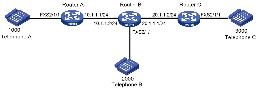
Network configuration
As shown in Figure 6, configure Router A, Router B, and Router C so that Telephone B as the conference initiator can establish a three-party conference with Telephone A and Telephone C.

Procedure
Make sure Router A, Router B, and Router C can reach each other before you configure them.
1. Configure Router A:
# Configure the destination IP address as 10.1.1.2 for VoIP entity 2000, and configure the called number as 2000.
<RouterA> system-view
[RouterA] voice-setup
[RouterA-voice] dial-program
[RouterA-voice-dial] entity 2000 voip
[RouterA-voice-dial-entity2000] address sip ip 10.1.1.2
[RouterA-voice-dial-entity2000] match-template 2000
[RouterA-voice-dial-entity2000] quit
# Configure the local number as 1000 for POTS entity 1000, and bind FXS interface line 2/1/1 to the POTS entity.
[RouterA-voice-dial] entity 1000 pots
[RouterA-voice-dial-entity1000] line 2/1/1
[RouterA-voice-dial-entity1000] match-template 1000
2. Configure Router B:
# Configure the destination IP address as 20.1.1.2 for VoIP entity 3000, and configure the called number as 3000.
<RouterB> system-view
[RouterB] voice-setup
[RouterB-voice] dial-program
[RouterB-voice-dial] entity 3000 voip
[RouterB-voice-dial-entity3000] address sip ip 20.1.1.2
[RouterB-voice-dial-entity3000] match-template 3000
[RouterB-voice-dial-entity3000] quit
# Configure the destination IP address as 10.1.1.1 for VoIP entity 1000, and configure the called number as 1000.
[RouterB-voice-dial] entity 1000 voip
[RouterB-voice-dial-entity1000] address sip ip 10.1.1.1
[RouterB-voice-dial-entity1000] match-template 1000
[RouterB-voice-dial-entity1000] quit
# Configure the local number as 2000 for POTS entity 2000, and bind FXS interface line 2/1/1 to the POTS entity.
[RouterB-voice-dial] entity 2000 pots
[RouterB-voice-dial-entity2000] line 2/1/1
[RouterB-voice-dial-entity2000] match-template 2000
3. Configure Router C:
# Configure the local number as 3000 for POTS entity 3000, and bind FXS interface line 2/1/1 to the POTS entity.
<RouterC> system-view
[RouterC] voice-setup
[RouterC-voice] dial-program
[RouterC-voice-dial] entity 3000 pots
[RouterC-voice-dial-entity3000] line 2/1/1
[RouterC-voice-dial-entity3000] match-template 3000
[RouterC-voice-dial-entity3000] quit
# Configure the destination IP address as 20.1.1.1 for VoIP entity 2000, and configure the called number as 2000.
[RouterC-voice-dial] entity 2000 voip
[RouterC-voice-dial-entity2000] address sip ip 20.1.1.1
[RouterC-voice-dial-entity2000] match-template 2000
Verifying the configuration
# Verify that Telephone B as the conference initiator can hold a three-party conference with Telephone A and Telephone C. (Details not shown.)
Example: Configuring MWI
Network configuration
As shown in Figure 7, Telephone A and Telephone B are registered with the VCX server (voice mail server) through Router A and Router B, respectively.
Configure voice mailbox access number 9000 for Telephone A on the VCX server. Configure unsolicited MWI on Router A, so that Telephone A can receive MWI messages.

Configuring the VCX server
· Configure the call processing server:
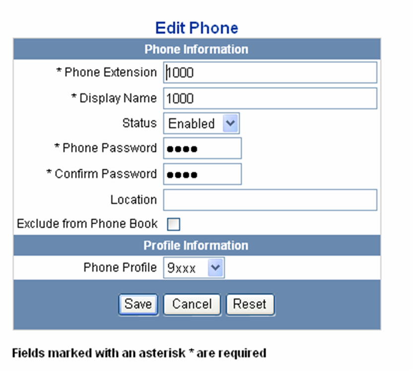
Open the Web interface of the server and select Central Management Console. Configure the telephone information of Telephone A and Telephone B, with the subscriber passwords as 1000 and 2000, respectively. Figure 8 uses Telephone A as an example.
Figure 8 Configuration page of call processing server (1)
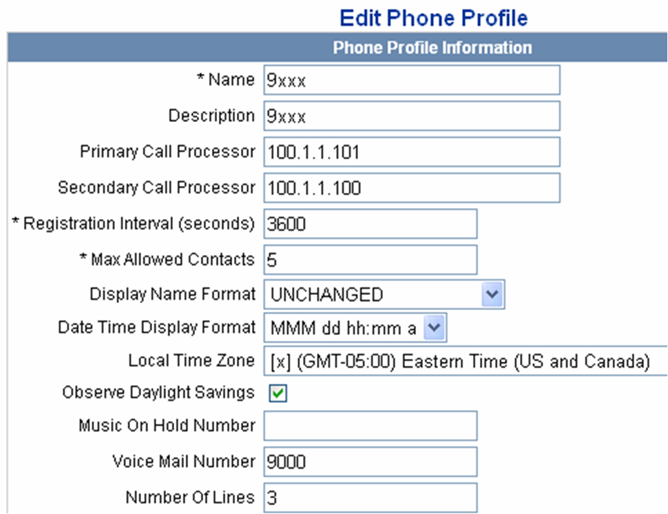
When you access the Edit Phone Profile page, as shown in Figure 9, type 9000 in the Voice Mail Number field.
Figure 9 Configuration page of call processing server (2)
· Configure the unified messaging server:
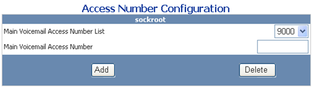
# Configure the mailbox access number as 9000.
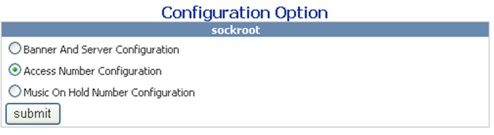
Open the Web interface of the server, select IP Messaging Web Provisioning to log in to the unified messaging server, and click the Configuration link. The Configuration Option box appears, as shown in Figure 10.
Figure 10 Configuration page of unified messaging server
Select 9000 from the Main Voicemail Access Number List, as shown in Figure 11.
Figure 11 Access number configuration page
# Configure the voice mailbox of Telephone A
Click the Edit A Mailbox link, enter the mailbox access number 9000 of Telephone A, and then check whether the mailbox is created successfully. If you are prompted that the mailbox is not present, click the Create/Delete Mailboxes link to create the mailbox of Telephone A, with the mailbox number as 9000.
Configuring Router A
# Configure VoIP entity 9000 to obtain the destination IP address through the SIP proxy server, and configure the called number as 9000 (mailbox access number) for the VoIP entity. This VoIP entity is used for Telephone A to dial the mailbox access number to log in to the voice mailbox.
<RouterA> system-view
[RouterA] voice-setup
[RouterA-voice] dial-program
[RouterA-voice-dial] entity 9000 voip
[RouterA-voice-dial-entity9000] address sip proxy
[RouterA-voice-dial-entity9000] match-template 9000
[RouterA-voice-dial-entity9000] quit
# Configure the local number as 1000 for POTS entity 1000, and bind FXS interface line 2/1/1 to the POTS entity.
[RouterA-voice-dial] entity 1000 pots
[RouterA-voice-dial-entity1000] line 2/1/1
[RouterA-voice-dial-entity1000] match-template 1000
[RouterA-voice-dial-entity1000] quit
[RouterA-voice-dial] quit
[RouterA] quit
# Enable MWI on FXS interface line 2/1/1.
[RouterA] subscriber-line 2/1/1
[RouterA-subscriber-line1/0] mwi
[RouterA-subscriber-line1/0] quit
# Specify the IP addresses for the proxy server, voice mail server, and registrar.
[RouterA] voice-setup
[RouterA-voice] sip
[RouterA-voice-sip] proxy ip 100.1.1.101
[RouterA-voice-sip] mwi-server ip 100.1.1.101 unsolicited
[RouterA-voice-sip] registrar 1 ip 100.1.1.101
Configuring Router B
# Configure VoIP entity 1000 to obtain the destination IP address through the SIP proxy server, and configure the called number as 1000 for the VoIP entity.
<RouterB> system-view
[RouterB] voice-setup
[RouterB-voice] dial-program
[RouterB-voice-dial] entity 1000 voip
[RouterB-voice-dial-entity1000] address sip proxy
[RouterB-voice-dial-entity1000] match-template 1000
[RouterB-voice-dial-entity1000] quit
# Configure the local number as 2000 for POTS entity 2000, and bind FXS interface line 2/1/1 to the POTS entity.
[RouterB-voice-dial] entity 2000 pots
[RouterB-voice-dial-entity2000] line 2/1/1
[RouterB-voice-dial-entity2000] match-template 2000
[RouterB-voice-dial-entity2000] quit
[RouterB-voice-dial] quit
[RouterB-voice] quit
[RouterB-voice] quit
# Specify the IP addresses for the proxy server and registrar.
[RouterB-voice] sip
[RouterB-voice-sip] proxy ip 100.1.1.101
[RouterB-voice-sip] registrar 1 ip 100.1.1.101
Verifying the configuration
# Use the display voice mwi command to verify the MWI setting for phone number 1000.
# Make a call from Telephone B to Telephone A, and do not pick up Telephone A. The call is forwarded to the voice mailbox after the ringing timer expires. Then, the subscriber of Telephone B can leave a message and hang up. The server sends a NOTIFY indicating that there is a new message in the mailbox of Telephone A to the voice gateway. By picking up the phone, the subscriber of Telephone A can hear the MWI tone, and then dial the voice mailbox access number to get the message.