- Table of Contents
- Related Documents
-
| Title | Size | Download |
|---|---|---|
| 01-Text | 1011.24 KB |
Establishing Layer 2 connectivity between a VM and an external device through a vTap NIC
Establishing Layer 2 connectivity between a VM and an external device through an SR-IOV NIC
Establishing Layer 3 connectivity between a VM and an external device through a vTap NIC
Setting up the deployment environment
Connecting the management host and the router
Configuring management IP addresses
Setting the number of CPU cores allocated to VMs
Identifying the file system format of the router
Selecting an automatic deployment procedure
Automatically deploying a VM from the CLI
Transferring the .pkg VM file to the destination router
Installing the .pkg file to deploy the VM
Automatically deploying a VM from a USB flash drive
Configuring VM networking settings
Configuring the vTap NIC of a VM
Configuring the SR-IOV PF of a VM
Manual VM deployment procedure
Importing the guest OS image file
Verifying that the vNICs are added successfully
Configuring VM network settings
Configuring the vTap NIC of a VM
Configuring the SR-IOV PF of a VM
Enabling or disabling VM auto-start
Introduction
This document guides you to deploy virtual machines (VMs) on RPE-X5E MPUs installed on an SR6600 router.
Supported VM operations
The router supports the following VM operations:
· Creating, deleting, or maintaining VM resources from the CLI.
· Installing and debugging the operating systems of VMs (guest OSs) from their Web GUI through VNC Viewer.
· Configuring the VMs to provide services.
About VM deployment
The router supports two MPUs, which are installed in the following slots:
· Slot 0 and slot 1 on the SR6604 and SR6608 routers.
· Slot 4 and slot 5 on the SR6616 router.
You can deploy VMs on any RPE-X5E MPUs in an SR6600 router or SR6600 IRF fabric. This guide uses an RPE-X5E MPU installed in slot 0 of a standalone SR6600 router as an example to describe the deployment procedures.
Supported vNICs
The VMs on the RPE-X5E MPU communicate with the router and connect to the network through vNICs.
The vNICs can be vTap NICs or physical functions (PFs) provided by single-root I/O virtualization (SR-IOV) NICs.
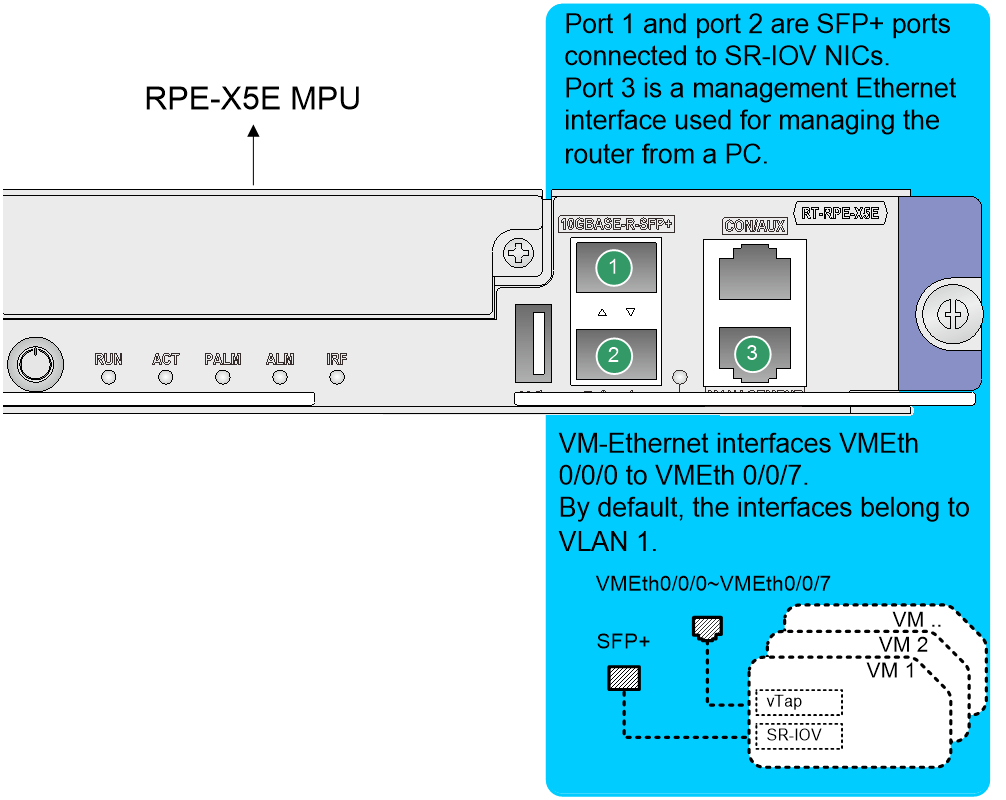
· A vTap NIC provides software-based forwarding through a VMEth interface on the router. It is slower than an SR-IOV vNIC. However, you do not need to install a driver for the vTap NICs. The system automatically binds a vTap NIC to a random VMEth interface when it is added to a VM. The VMEth interfaces available on the router are VMEth0/0/0 through VMEth0/0/7.
· An SR-IOV NIC provides hardware-based forwarding for VMs through its physical functions (PFs). It forwards traffic at a higher speed than vTap NICs. The RPE-X5E MPU has two SR-IOV NICs, which are available to VMs as SR-IOV PF0 and SR-IOV PF1. SR-IOV PF0 and PF1 are bound to the SFP+ port 0 and SFP+ port 1 on the MPU, respectively. To use the SR-IOV PFs, you must install transceiver modules in the SPF+ ports and connect them to the network.
Figure 1 Interfaces on the RPE-X5E MPU
VM networking
A VM can communicate with an external device in bridged mode at Layer 2 or in routed mode at Layer 3 depending on your networking method.
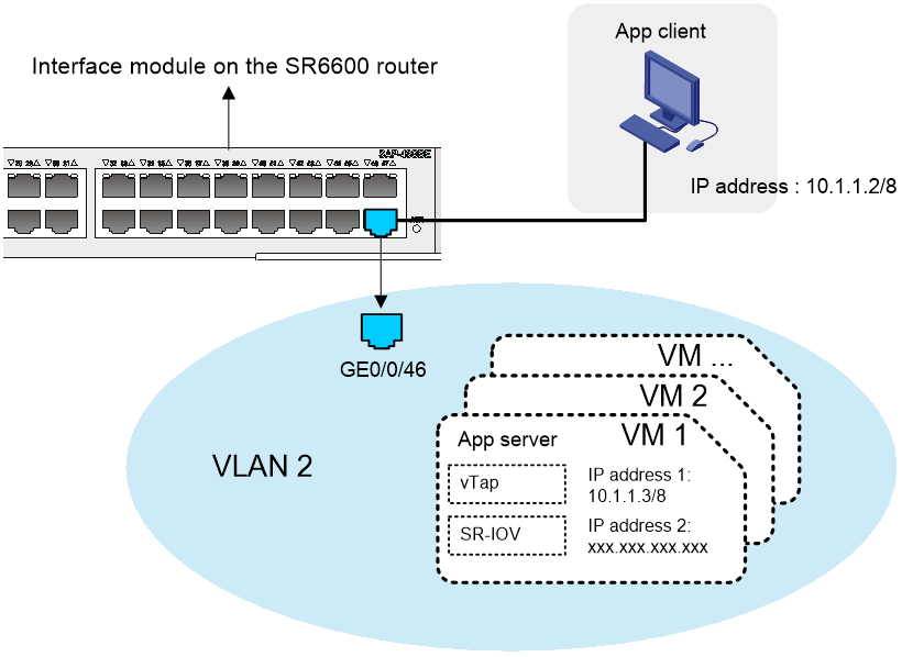
Establishing Layer 2 connectivity between a VM and an external device through a vTap NIC
To enable a VM to communicate with an external device at Layer 2 through a vTap NIC:
1. Connect the external device to a Layer 2 Ethernet interface on the router.
2. Add this interface to the same VLAN as the vNIC.
3. Assign the vNIC an IP address in the same subnet as the external device.
Figure 2 Network setup for Layer 2 connectivity through a vTap NIC
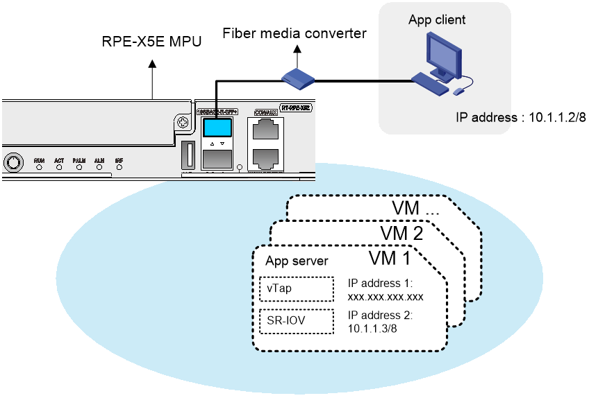
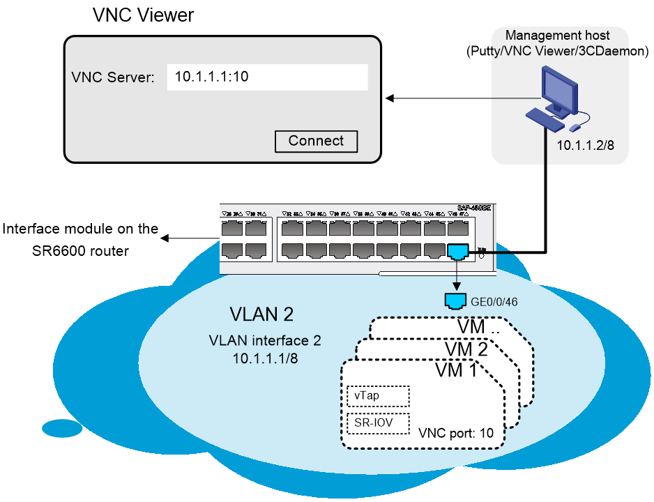
Establishing Layer 2 connectivity between a VM and an external device through an SR-IOV NIC
To enable a VM to communicate with an external device at Layer 2 through an SR-IOV NIC:
1. Connect the external device to an SFP+ port on the RPE-X5E MPU.
2. Assign the vNIC an IP address in the same subnet as the external device.
Figure 3 Network setup for Layer 2 connectivity through an SR-IOV NIC
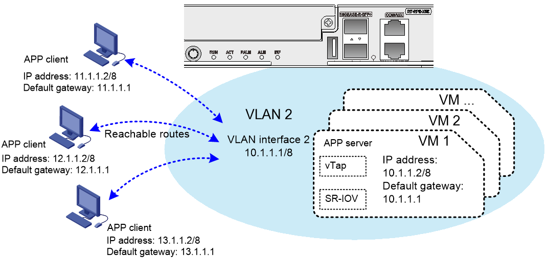
Establishing Layer 3 connectivity between a VM and an external device through a vTap NIC
To enable a VM to communicate with an external device in different subnets through a vTap NIC, establish Layer 3 connectivity between them as follows:
1. Connect the external device to a Layer 2 or Layer 3 Ethernet interface on the router.
2. If a Layer 2 Ethernet interface is used, assign this interface to a VLAN, create the VLAN interface, and assign an IP address to the VLAN interface. If a Layer 3 Ethernet interface is used, assign an IP address to it.
3. Set the default gateway of the external device to the IP address of the VLAN interface or Layer 3 Ethernet interface.
4. Assign the vNIC of the VM to a VLAN, create the VLAN interface, and assign an IP address to the VLAN interface.
5. Set the default gateway of the VM to the IP address of the VLAN interface.
Figure 4 Network setup for Layer 3 connectivity through a vTap NIC
VM deployment modes
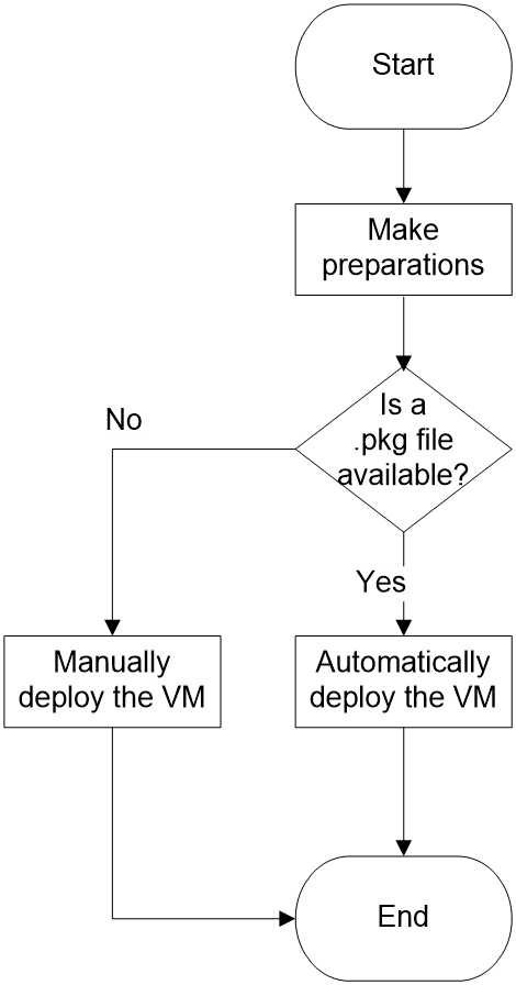
The router supports both automatic and manual VM deployment modes, as shown in Figure 5.
· Automatic VM deployment—Bulk-deploy VMs by using a .pkg VM file. A .pkg file contains all files that make up a VM. All VMs created from a .pkg file have the same parameter settings as the source VM, including their guest OS, CPU and memory settings. After a VM is deployed, you can tune its settings as needed. For more information about automatic VM deployment, see "Automatically deploying a VM."
Depending on the storage medium used to store the .pkg VM file, the following automatic deployment methods are available:
¡ CLI-based automatic VM deployment—If you store the .pkg file on a disk of the router, use this method to deploy the VM from the CLI of the router.
¡ USB-based automatic VM deployment—If you store the .pkg file on a USB flash drive, use this method. To install the VM, you only need to reboot the router after you insert the USB flash drive.
· Manual VM deployment—Create and set up VMs from the CLI of the router. Manual VM deployment is more complicated than automatic VM deployment. Typically, use manual deployment only if you do not have a .pkg VM file or cannot export one from an existing VM. Manual VM deployment allows you to customize VM parameters on a per-VM basis, such as the number of vCPUs, memory size, and operating system. For more information about manual VM deployment, see "Manually deploying a VM."
VM GUI login method
Use VNC Viewer to log in to the GUI of a VM by connecting to the VNC server on the router. In VNC Viewer, enter the server address in VNC server IP address:VNC port number format.
· VNC server IP address—The IP address of a Layer 3 Ethernet interface or a VLAN interface on the router.
· VNC port number—The VNC port number configured when the VM is deployed.
|
|
NOTE: The VNC server IP address in this document is the IP address of a Layer 3 interface on the router. |
Figure 6 VM GUI login through a Layer 3 Ethernet interface
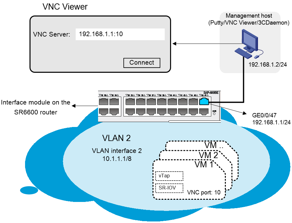
Figure 7 VM GUI login through a VLAN interface
Preparing for VM deployment
Before you deploy VMs, perform the following tasks:
· Setting up the deployment environment
· Connecting the management host and the router
· Configuring management IP addresses
· Setting the number of CPU cores allocated to VMs
· Identifying the file system format of the router
Setting up the deployment environment
· Prepare a management host, a network cable, and a serial cable.
· To access the router through the console port, install a terminal emulation program (for example, Putty) on the management host.
· To access the GUI of the VM, install VNC Viewer.
· To transfer VM deployment files to the router, install FTP software, 3CDaemon for example.
Connecting the management host and the router
· Use the serial cable to connect the host to the console port of the router.
· Connect the management host to an Ethernet port on the router for file transfer and data transmission.
Figure 8 Network scheme
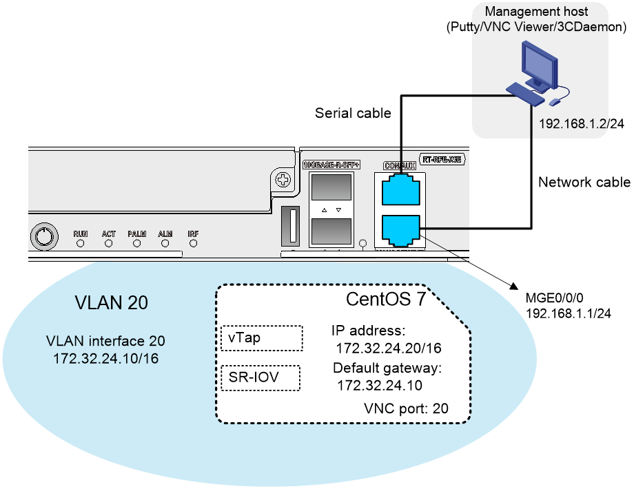
Table 1 Component description
|
Component name |
Description |
|
Management host |
The host from which you deploy VMs and log in to the GUI of a VM. |
|
MGE0/0/0 |
Management Ethernet interface. |
|
vTap |
vTap NIC. |
|
SR-IOV |
SR-IOV NIC. |
Configuring management IP addresses
1. Configure IP address settings for the management host:
a. On the management host, open the Network and Sharing Center and select Local Area Connection.
b. In the dialog box that opens, click Properties.
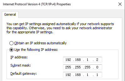
c. In the dialog box that opens, select Internet Protocol Version 4 (TCP/IPv4) and click Properties.
d. In the dialog box that opens, configure the IP address settings.
In this example, the IP address is 192.168.1.2/24.
Figure 9 Configuring IP address settings for the management host
2. On the router, assign an IP address to the management Ethernet interface:
# Enter system view, and then enter the view of the management Ethernet interface.
<H3C> system-view
[H3C] interface m-gigabitethernet0/0/0
# Assign 192.168.1.1/24 to the interface, and then return to system view..
[H3C-m-gigabitethernet0/0/0] ip address 192.168.1.1 24
[H3C-m-gigabitethernet0/0/0] quit
Setting the number of CPU cores allocated to VMs
The router software has the control plane, data plane, and VM plane. By default, the control plane uses one CPU core, and the data plane uses the remaining CPU cores. To deploy VMs, you must first allocate CPU cores to the VM plane. The RPE-X5E MPU has eight CPU cores. To ensure correct operation, assign a maximum of six CPU cores to the VM plane.
To modify the number of CPU cores allocated to VMs:
1. Enter system view, and then allocate two CPU cores to the VM plane.
<H3C> system-view
[H3C] set vcpu-pool slot 0 2
……
2. Reboot the router for the allocation to take effect.
<H3C> reboot
Identifying the file system format of the router
About storage devices
The router provides built-in disk sda for VM deployment. By default, sda is partitioned into sda0 and sda1. You can deploy VMs on partition sda1, which is used to store configuration files of VMs. If you attach external disk hda0 to the RPE-X5E MPU, you can alternatively deploy VMs on this disk.
Partition sda0 typically stores the Comware software image files and configuration files of the router.
Procedure
1. Verify that the file system format of partition sda1 is EXT4 on the router:
<H3C> dir slot0#sda1:/
Directory of sda1: (EXT4)
……
|
|
NOTE: For more information about the dir command, see Fundamentals Command Reference in H3C SR6600[SR6600-X] Routers Command References. |
2. If the format of a file system is not EXT4, use the format command to format it and reboot the router.
|
|
CAUTION: If the disk contains useful data, back up the data before you format the disk. This command will clear data from the file system. |
<H3C> format slot0#sda1: ext4
All data on sda1: will be lost, continue? [Y/N]:Y
……
<H3C> reboot
|
|
NOTE: For more information about the format command, see Fundamentals Command Reference in H3C SR6600[SR6600-X] Routers Command References. |
Automatically deploying a VM
Selecting an automatic deployment procedure
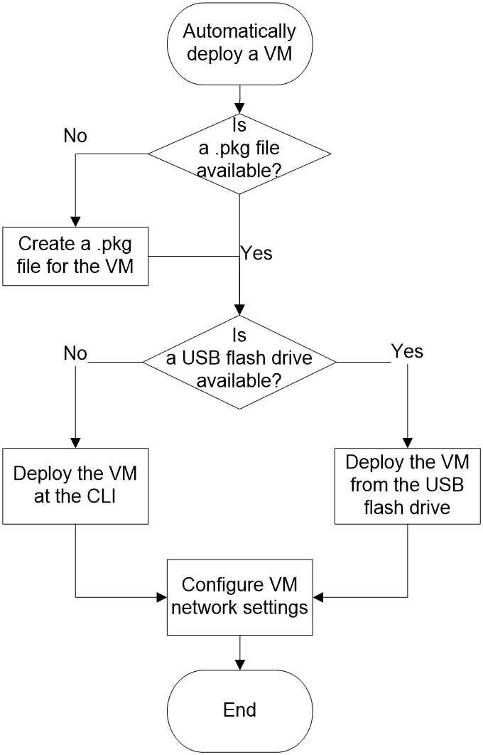
Figure 10 shows the automatic VM deployment workflow.
If you have a USB flash drive, select USB-based automatic deployment.
If you do not have a USB flash drive or do not need to reboot the router, select CLI-based automatic deployment.
Figure 10 Automatic VM deployment workflow
Creating a .pkg VM file
About this task
This task exports an existing VM as a .pkg file.
Procedure
1. Verify that the source VM is operating correctly and shut it down:
a. Log in to the source VM from VNC Viewer to verify that the VM is operating correctly.
b. Shut down the VM.
<H3C> system-view
[H3C] vmm
[H3C-vmm] stop vm slot 0 centos7
c. Verify that the VM has shut down.
[H3C-vmm] display vmlist slot 0
Id Name Status
------------------------------------------
1 centos7 shut off
2. Create a .pkg VM file.
[H3C-vmm] export slot 0 vm centos7 slot0#sda1:/centos7.pkg
3. Copy the .pkg file to the destination directory.
¡ Copy the file to the sda1:/VmImages/ directory on the local router.
<H3C> copy slot0#sda1:/centos7.pkg slot0#sda1:/VmImages/
¡ Copy the file to a USB flash drive.
# (Optional.) Format the USB flash drive.
|
|
IMPORTANT: If the size of the .pkg file exceeds 4 GB, you must first change the file system format of the USB flash drive to EXT4. |
<H3C> format usba0: ext4
All data on usba0: will be lost, continue? [Y/N]:Y
……
# Copy the file to a directory on the USB flash drive.
<H3C> copy slot0#sda1:/centos7.pkg usba0:/
|
|
NOTE: For more information about the format and copy commands, see Fundamentals Command Reference in H3C SR6600[SR6600-X] Routers Command References. |
Automatically deploying a VM from the CLI
Transferring the .pkg VM file to the destination router
About this task
You can transfer the .pkg VM file from the source router to the destination router through a USB flash drive or through FTP.
Prerequisites
Make sure you have exported a VM as a .pkg VM file on the source router. For more information about the procedure, see "Creating a .pkg VM file."
Transferring the .pkg file through a USB flash drive
1. Insert the USB flash drive into the source router, and copy the .pkg file to the USB flash drive.
2. Insert the USB flash drive in the destination router.
3. Copy the .pkg file to the root directory of partition sda1 on the router.
<H3C> copy usba0:/centos7.pkg slot0#sda1:/
Transferring the .pkg file through FTP
This procedure uses the management host as the FTP server and the destination router as the FTP client.
1. Set up an FTP server on the management host with 3CDaemon. (Details not shown.)
2. On the destination router, download the .pkg file by using FTP:
# Change the current working directory to the root directory of partition sda1 on the router.
<H3C> cd slot0#sda1:/
# Access the FTP server.
<H3C> ftp 192.168.1.2
Press CTRL+C to abort.
Connected to 192.168.1.2 (192.168.1.2).
220 3CDaemon FTP Server Version 2.0
# Enter the FTP username and password.
User (192.168.1.2:(none)): 1234
331 password required for 1234
Password:
230 User logged in
Remote system type is UNIX.
Using binary mode to transfer files.
# Set the file transfer mode to binary.
ftp> binary
# Download the .pkg file to the root directory of partition sda1 on the router and save the file.
ftp> get centos7.pkg
……
226 Closing data connection; File transfer successful.
4521459712 bytes received in 385.518 seconds (11.18 Mbytes/s)
ftp> quit
|
|
NOTE: For more information about the get command, see Fundamentals Command Reference in H3C SR6600[SR6600-X] Routers Command References. |
Installing the .pkg file to deploy the VM
About this task
The amount of time used to deploy a VM depends on the size of the .pkg VM file.
For a VM to communicate with external devices, assign its NICs to a VLAN, for example, VLAN 20.
Procedure
1. Enter system view, and then execute the vmm command to enter VMM view.
<H3C> system-view
[H3C] vmm
[H3C-vmm]
2. Execute the install vm-pkg command to install the VM.
For example, install VM centos7 on slot 0.
[H3C-vmm] install slot 0 vm-pkg slot0#sda1:/centos7.pkg
install VM package centos7.pkg...
After the VM is installed successfully, the system displays the following VMM view prompt:
[H3C-vmm]
3. Execute the display vminterface command to identify the MAC address of the vTap NIC on the VM. You will need this information when you assign the vTap NIC to a VLAN.
For example, identify the MAC address of the vTap NIC on VM centos7.
[H3C-vmm] display vminterface vm slot 0 centos7
Interface Type Model MAC
-----------------------------------------------------------
VMEth0/0/0 ethernet e1000 4077-A9A1-5453
PF0 hostdev - 04D7-A557-9603
[H3C-vmm] quit
4. Enter system view, and then create VLAN 20 and its VLAN interface. Then, assign an IP address to VLAN-interface 20.
[H3C] vlan 20
[H3C-vlan 20] quit
[H3C] interface vlan-interface 20
[H3C-vlan-interface 20] ip address 172.32.24.10 16
[H3C-vlan-interface 20] quit
5. Enter VMM view, and then execute the set vtap vm command to assign the vTap NIC of the VM to VLAN 20.
[H3C] vmm
[H3C-vmm] set vtap vm slot 0 centos7 mac 4077-A9A1-5453 vlan 20
Automatically deploying a VM from a USB flash drive
1. Create a .pkg VM file from a VM on the source router and store the file in a USB flash drive.
For information about the procedure, see "Creating a .pkg VM file."
2. Insert the USB drive into the USB port on an RPE-X5E MPU of the destination router.
For example, insert the USB drive into the MPU in slot 0.
3. Reboot the MPU for VM deployment.
<H3C> reboot slot 0
|
|
NOTE: The amount of time used to deploy a VM depends on the size of the .pkg VM file. |
After the VM is installed, the following user view prompt appears:
[H3C]
4. Enter system view, and then execute the vmm command to enter VMM view.
<H3C> system-view
[H3C] vmm
[H3C-vmm]
5. Execute the display vminterface command to identify the MAC address of the vTap NIC on the VM. You will need this information when you assign the vTap NIC to a VLAN.
For example, identify the MAC address of the vTap NIC on VM centos7.
[H3C-vmm] display vminterface vm slot 0 centos7
Interface Type Model MAC
-----------------------------------------------------------
VMEth0/0/0 ethernet e1000 4077-A9A1-5453
PF0 hostdev - 04D7-A557-9603
[H3C-vmm] quit
6. Enter system view, and then create VLAN 20 and its VLAN interface. Then, assign an IP address to VLAN-interface 20.
[H3C] vlan 20
[H3C-vlan 20] quit
[H3C] interface vlan-interface 20
[H3C-vlan-interface 20] ip address 172.32.24.10 16
[H3C-vlan-interface 20] quit
7. Enter VMM view, and then execute the set vtap vm command to assign the vTap NIC of the VM to VLAN 20.
[H3C] vmm
[H3C-vmm] set vtap vm slot 0 centos7 mac 4077-A9A1-5453 vlan 20
Configuring VM networking settings
To configure the network settings of a VM:
3. Configuring the SR-IOV PF of a VM
|
|
NOTE: The following information uses a CentOS to describe the network setup procedure. The GUIs differ depending on the guest OS. |
Logging in to the VM GUI
1. Enter system view, and then execute the vmm command to enter VMM view.
<H3C> system-view
[H3C] vmm
[H3C-vmm]
2. Execute the start vm command to start the VM.
For example, start VM centos7 on slot 0.
[H3C-vmm] start vm slot 0 centos7
Domain centos7 started
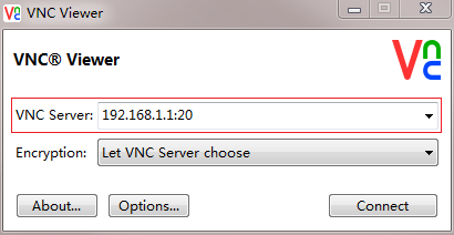
3. On the management host, open VNC Viewer, and log in to the VM GUI in the format of VNC server IP address:VNC port number, as shown in Figure 11.
Figure 11 VM login interface in VNC Viewer

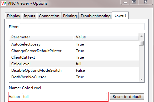
4. If VNC Viewer closes incorrectly, re-open it and set the VNC configuration color level to full, as shown in Figure 12.
Figure 12 Modifying the color level

Configuring the vTap NIC of a VM
About this task
After a VM is deployed, you must assign a vTap NIC to the VM and assign an IP address to the vTap NIC for the VM to communicate with external devices.
Procedure
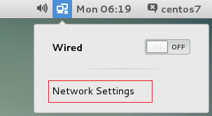
1. On the desktop of the guest OS (CentOS 7 in this example), click Network Settings, as shown in Figure 13.
Figure 13 Network Settings option
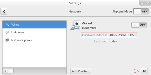
2. Find the vTap NIC based on its MAC address, and then click the gear icon in the lower right corner to configure the NIC. In this example, the MAC address of the vTap NIC is 4077-A9A1-5453.
Figure 14 Configuring the vTap NIC
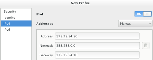
3. Select an IP version and configure the IP address and gateway settings for the vTap NIC, as shown in Figure 15. In this example, select IPv4.
Figure 15 Configuring IP address and gateway settings
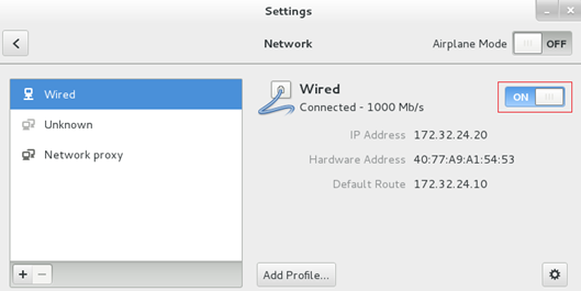
4. Disable and then re-enable the vTap NIC for the configuration to take effect, as shown in Figure 16.
Figure 16 Disabling and re-enabling a vNIC
5. Verify the network connectivity to the management host and the router.
a. Examine the settings of the firewall in the guest OS. Disable the firewall or configure the firewall to permit the traffic between the VM and the router and the traffic between the VM and the management host.
b. Execute the ping command to verify that the VM can communicate with the management host and the router.
Configuring the SR-IOV PF of a VM
|
|
IMPORTANT: You must assign IP addresses from different subnets to the vTap NIC and SR-IOV PF of a VM. |
1. Connect the fiber ports on the VM hosting MPU to the network.
The SR-IOV NICs on an MPU become available when you connect the fiber ports on the MPU to the network.
2. Assign an IP address to the SR-IOV PF used by a VM on the MPU.
For more information about the IP assignment procedure, see "Configuring the vTap NIC of a VM."
Manually deploying a VM
Manual VM deployment procedure
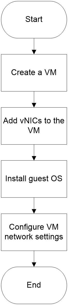
To deploy a VM manually:
4. Configuring VM network settings
Figure 17 Manual VM deployment workflow
Creating a VM
To create a VM:
1. Importing the guest OS image file
Importing the guest OS image file
Restrictions and guidelines
The guest OS image file name is case sensitive and cannot exceed 63 characters.
Procedure
1. Put the guest OS image file in a file path on the FTP server.
2. On the router, download the image file to the root directory of a disk, for example, to the root directory of disk sda1.
# Change the current working directory to the root directory of disk sda1 on slot 0.
<H3C> cd slot0#sda1:/
# Connect to the FTP server.
<H3C> ftp 192.168.1.2
Press CTRL+C to abort.
Connected to 192.168.1.2 (192.168.1.2).
220 3CDaemon FTP Server Version 2.0
# Enter the FTP username and password. The FTP username and password must be the same as those configured on the FTP server.
User (192.168.1.2:(none)): 1234
331 password required for 1234
Password:
230 User logged in
Remote system type is UNIX.
Using binary mode to transfer files.
# Set the file transfer mode to binary to ensure the integrity of the transferred file.
ftp> binary
# Download the image file. The image file will be stored in the root directory of disk sda1 on slot 0, which is the current working directory. In this example, the image file is centos7.iso.
ftp> get centos7.iso
……
When the file transfer finishes successfully, the router displays the following messages:
226 Closing data connection; File transfer successful.
4521459712 bytes received in 385.518 seconds (11.18 Mbytes/s)
# Terminate the FTP connection.
ftp> quit
Installing the VM
1. Enter system view, and then execute the vmm command to enter VMM view.
<H3C> system-view
[H3C] vmm
[H3C-vmm]
2. Execute the create-disk command to create a disk for the VM.
In this example, the disk file path is sda1:/centos7.qcow on slot 0, disk size is 30 GB, and file system format is QCOW2.
[H3C-vmm] create-disk slot0#sda1:/centos7.qcow size 30 format qcow2
|
|
NOTE: VMs cannot share disks. The disks created for a VM can be used only by that VM. |
3. Execute the install vm-name command to install the VM.
This example creates a VM named centos7 and assigns two vCPUs and a memory size of 1 GB to it. Its VNC port number is 12. Its disk path is sda1:/centos7.qcow on slot 0, file system format is QCOW2, and disk BUS type is IDE. Its CD-ROM image path is sda1:/centos7.iso on slot 0.
[H3C-vmm] install slot 0 vm-name centos7 vcpu 2 memory 1024000 vncport 20 disk slot0#sda1:/centos7.qcow format qcow2 disk-bus ide cdrom slot0#sda1:/centos7.iso
If the VM is installed successfully, the router displays the following message:
Domain centos7 defined successfully
Adding vNICs to a VM
To add vNICs to a VM:
2. Adding an SR-IOV PF to a VM
3. Verifying that the vNICs are added successfully
Adding a vTap NIC to a VM
About this task
A vTap NIC is uniquely identified by its MAC address. The router has reserved eight MAC addresses for vTap NICs. You can add a vTap NIC only to one VM.
Procedure
For example, create VLAN 20 and its VLAN interface. Then, assign an IP address to VLAN-interface 20.
<H3C> system-view
[H3C] vlan 20
[H3C-vlan 20] quit
[H3C] interface vlan-interface 20
[H3C-vlan-interface 20] ip address 172.32.24.10 16
[H3C-vlan-interface 20] quit
2. Enter system view, and then execute the vmm command to enter VMM view.
[H3C] vmm
[H3C-vmm]
3. Obtain the MAC addresses of vTap NICs.
[H3C-vmm] add vtap vm slot 0 centos7 mac ?
04D7-A557-96FB
04D7-A557-96FC
04D7-A557-96A1
04D7-A557-96B2
04D7-A557-96D1
04D7-A557-96F6
04D7-A557-96C3
04D7-A557-9662
4. Select the MAC address of an unused vTap NIC to the VM and bind the NIC to VLAN 20.
This example selects the vTap NIC with MAC address 04D7-A557-96FB.
[H3C-vmm] add vtap vm slot 0 centos7 mac 04D7-A557-96FB vlan 20
Adding an SR-IOV PF to a VM
About this task
The RPE-X5E MPU has two SR-IOV NICs, which are available to VMs as SR-IOV PF 0 and SR-IOV PF 1.
When you add an SR-IOV PF to a VM, you do not need to assign it to a VLAN.
Procedure
1. Enter system view, and then execute the vmm command to enter VMM view.
<H3C> system-view
[H3C] vmm
[H3C-vmm]
2. Add an SR-IOV PF to the VM.
For example, add SR-IOV PF 0 to VM centos7.
[H3C-vmm] add sriov vm slot 0 centos7 pf 0
Verifying that the vNICs are added successfully
Execute the display vminterface command to verify that the vNICs have been added.
<H3C> display vminterface vm slot 0 centos7
Interface Type Model MAC
-----------------------------------------------------------------
VMEth0/0/0 ethernet e1000 04D7-A557-96FB
PF0 hostdev - 04D7-A557-9603
Installing a guest OS
To install a guest OS:
2. Installing the guest OS in the VM
Logging in to the VM GUI
1. Execute the start vm command to start the VM.
For example, start VM centos7 on slot 0.
<H3C> system-view
[H3C] vmm
[H3C-vmm] start vm slot 0 centos7
Domain centos7 started
2. On the management host, open VNC Viewer, and log in to the VM GUI in the format of VNC server IP address:VNC port number, as shown in Figure 18.
Figure 18 VM login interface in VNC Viewer
3. If VNC Viewer closes incorrectly, re-open it and set the VNC configuration color level to full, as shown in Figure 19.
Figure 19 Modifying the color level
Installing the guest OS in the VM
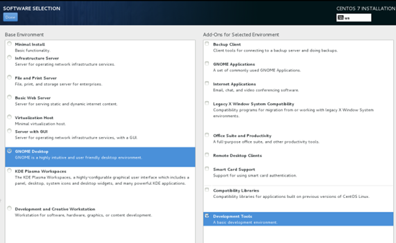
After you log in to the VM GUI, install the guest OS as instructed. When you select software, select the GNOME Desktop and Development Tools options.
Figure 20 Selecting software
Configuring VM network settings
Configuring the vTap NIC of a VM
For more information about the vTap NIC configuration procedure, see "Configuring the vTap NIC of a VM."
Configuring the SR-IOV PF of a VM
About this task
For the SR-IOV PF of a VM to operate correctly, you must install the SR-IOV driver in the guest OS.
· If the guest OS is Linux, install Intel® Network Adapter Driver for PCIe* Intel® 10 Gigabit Ethernet Network Connections Under Linux*.
· If the guest OS is Windows Server 2012, install the SR-IOV driver for Windows Server 2012 is Intel® Network Adapter Driver for Windows Server 2012*.
To assign an IP address to an SR-IOV PF, you must make sure the SFP+ port bound to it has a physical connection.
Prerequisites
1. Make sure you have configured the vTap NIC of the VM to provide network services.
2. Download the SR-IOV driver to a directory on the FTP server. In this example, FTP server is on the management host.
¡ To download Intel® Network Adapter Driver for PCIe* Intel® 10 Gigabit Ethernet Network Connections Under Linux*, access
https://downloadcenter.intel.com/zh-cn/download/14687
¡ To download the Intel® Network Adapter Driver for Windows Server 2012*, access
https://downloadcenter.intel.com/zh-cn/download/21694
|
|
NOTE: If the download links are inaccessible, access the Intel download center to download the SR-IOV driver. |
3. To use the make command for SR-IOV driver compilation and installation, you must make sure the guest OS contains a compiler and the kernel header file. If they are not available, search the Internet for Linux compiler and kernel file installation methods, and install them as instructed.
4. Install transceiver modules in the SFP+ ports bound to the SR-IOV NICs, and then connect the ports to the network. This step enables the SR-IOV PFs.
Procedure
1. Installing the SR-IOV driver
2. Assigning an IP address to an SR-IOV PF of the VM
3. Verifying the connectivity of the SR-IOV NIC
Installing the SR-IOV driver
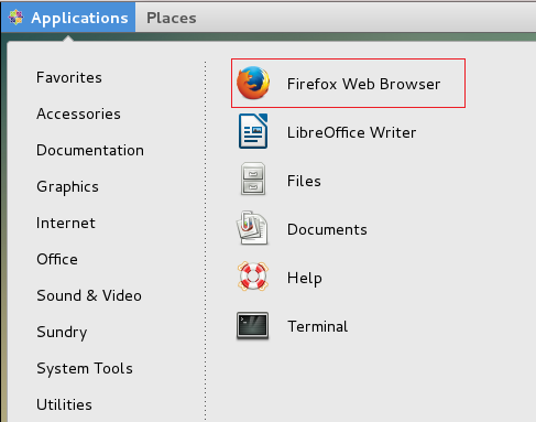
1. Open the Firefox browser in the CentOS system.
Figure 21 Opening the Firefox browser
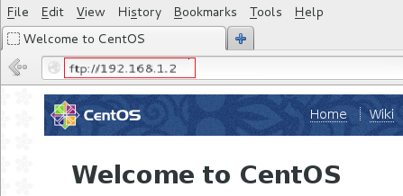
2. Enter the FTP server address, find the driver file, and save the file on the VM. In this example, the driver file is ixgbe-5.3.4.tar.gz.
Figure 22 Accessing the FTP server
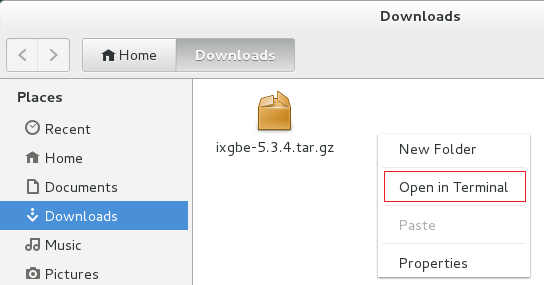
3. Open the directory that stores the driver file, select the driver file, right-click in the blank space, and then select Open in Terminal.
Figure 23 Opening the driver file
4. Access the CentOS CLI to install the driver.
[centos7@localhost~]# su
password:
[root@localhost~]# mv ixgbe-5.3.4.tar.gz /tmp
[root@localhost~]# cd /tmp
[root@localhost tmp]# tar –xzvf ixgbe-5.3.4.tar.gz
[root@localhost tmp]# cd ixgbe-5.3.4/src
[root@localhost src]# make
[root@localhost src]# make install
Assigning an IP address to an SR-IOV PF of the VM
See "Configuring the vTap NIC of a VM."
Verifying the connectivity of the SR-IOV NIC
Execute the ping command to verify that the VM can communicate with the management host and the router through the SR-IOV PF.
Managing VMs
This document provides only basic information about VM management tasks.
For detailed information about VM resource management tasks, see Virtual Technologies Configuration Guide in H3C SR6600[SR6600-X] Routers Configuration Guides.
For detailed information about VM management commands and parameters, see Virtual Technologies Command Reference in H3C SR6600[SR6600-X] Routers Command References.
Starting a VM
1. Enter system view, and then execute the vmm command to enter VMM view.
<H3C> system-view
[H3C] vmm
2. Execute the start vm slot slot-number vm-name command to start a VM.
For example, start VM centos7 on slot 0.
[H3C-vmm] start vm slot 0 centos7
Shutting down a VM
About this task
Shutting down a VM takes about 6 minutes.
If a VM cannot be normally shut down, use either of the following methods to forcibly shut down the VM:
· Execute the stop command with the force keyword.
· Use the power button on the RPE-X5E MPU to power off and then power on the MPU.
Procedure
1. Enter system view, and then execute the vmm command to enter VMM view.
<H3C> system-view
[H3C] vmm
2. Execute the stop vm slot slot-number vm-name [ force ] command to shut down the VM.
For example, shut down VM centos7 on slot 0.
[H3C-vmm] stop vm slot 0 centos7
Enabling or disabling VM auto-start
About this task
To have a VM automatically start up when the router or its hosting RPE-X5E MPU starts up, enable VM auto-start.
You can change the enabling state of VM auto-start while the VM is running or is down.
· If you change the feature state while the VM is running, you must restart the VM for the change to take effect.
· If you change the feature state while the VM is down, the setting takes effect when the VM starts up.
Procedure
1. Enter system view, and then execute the vmm command to enter VMM view.
<H3C> system-view
[H3C] vmm
2. Enable auto-start for a VM:
¡ To enable VM auto-start, execute the autostart vm slot slot-number vm-name command.
For example, enable VM auto-start for VM centos7 on slot 0.
[H3C-vmm] autostart vm slot 0 centos7
¡ To disable VM auto-start, execute the undo autostart vm slot slot-number vm-name command.
For example, disable VM auto-start for VM centos7 on slot 0.
[H3C-vmm] undo autostart vm slot 0 centos7
3. If you change the feature state while the VM is running, execute the stop command and then the start command to restart the VM for the setting to take effect. Alternatively, you can restart the VM from the VM desktop.
Backing up a VM
About this task
To back up a VM for future use such as VM restoration, you must first shut down that VM. The backup file is a .vmb file.
Procedure
1. Enter system view, and then execute the vmm command to enter VMM view.
<H3C> system-view
[H3C] vmm
2. Execute the backup vm slot slot-number vm-name backup-path command to back up a VM.
For example, back up VM centos7 on slot 0.
[H3C-vmm] backup vm slot 0 centos7 slot0#sda1:/centos7.vmb
Restoring a VM
About this task
Perform this task to restore a VM from a .vmb backup file.
This operation reverts the VM to the state when the .vmb backup file was generated.
Procedure
1. Enter system view, and then execute the vmm command to enter VMM view.
<H3C> system-view
[H3C] vmm
2. Execute the restore slot slot-number pakagepath backup-image-path command to restore a VM.
For example, restore VM centos7 on slot 0.
[H3C-vmm] restore slot 0 pakagepath slot0#sda1:/centos7.vmb
Exporting a .pkg VM file for automatic deployment
About this task
To deploy identical VMs on multiple SR6600 routers, perform this task.
This task enables you to create a .pkg file from a VM on one SR6600 router. Then, you can use that .pkg file to deploy VMs identical to the source VM on other SR6600 routers.
Procedure
1. Enter system view, and then execute the vmm command to enter VMM view.
<H3C> system-view
[H3C] vmm
2. Execute the stop vm slot slot-number vm-name [ force ] command to shut down a VM.
For example, shut down VM centos7 on slot 0.
[H3C-vmm] stop vm slot 0 centos7
3. Execute the export vm slot slot-number vm-name pkg-path command to export the VM to a .pkg file.
For example, export VM centos7 to the centos7.pkg file.
[H3C-vmm] export vm slot 0 centos7 slot0#sda1:/centos7.pkg
Uninstalling a VM
Prerequisites
Make sure the VM has been shut down.
Procedure
1. Enter system view, and then execute the vmm command to enter VMM view.
<H3C> system-view
[H3C] vmm
2. Execute the uninstall vm slot slot-number vm-name command to uninstall a VM.
For example, uninstall VM centos7 on slot 0.
[H3C-vmm] uninstall vm slot 0 centos7
Adding disks to expand a VM
About this task
You can change the enabling state of VM auto-start while the VM is running or is down.
· If you add disks while the VM is running, you must restart the VM for the change to take effect.
· If you add disks while the VM is down, the setting takes effect when the VM starts up.
Procedure
1. Enter system view, and then execute the vmm command to enter VMM view.
<H3C> system-view
[H3C] vmm
2. Execute the create-disk disk-file size size format { raw | qcow2 } command to create a disk.
For example, create a 30 GB disk in QCOW2 format to VM centos7. The disk file name is centos7.qcow.
[H3C-vmm] create-disk slot0#sda1:/centos7.qcow size 30 format qcow2
3. Execute the add disk vm vm-name format { raw | qcow2 } disk-file path-file disk-bus { ide | virtio } command to add the disk to a VM.
For example, add disk centos7.qcow to VM centos7 and set the disk hub type to IDE.
[H3C-vmm] add disk vm slot 0 centos7 format qcow2 disk-file slot0#sda1:/centos7.qcow disk-bus ide
4. If you add a disk while the VM is running, execute the stop command and then the start command to restart the VM for the setting to take effect. Alternatively, you can restart the VM from the VM desktop
Display and maintenance commands for VM management
Execute display commands in any view.
|
Command |
|
|
Display the VM list. |
In standalone mode: display vmlist [ slot slot-number ] In IRF mode: display vmlist [ chassis chassis-number slot slot-number ] |
|
Display detailed information about a VM. |
In standalone mode: display vm slot slot-number vm-name [ static-configuration ] In IRF mode: display vm chassis chassis-number slot slot-number vm-name [ static-configuration ] |
|
Display the VNC port number of a VM. |
In standalone mode: display vncport vm slot slot-number vm-name In IRF mode: display vncport vm chassis chassis-number slot slot-number vm-name |
|
Display information about the disks and CD-ROM of a VM. |
In standalone mode: display vmdisklist vm slot slot-number vm-name In IRF mode: display vmdisklist vm chassis chassis-number slot slot-number vm-name |
|
Display disk usage information about a VM. |
In standalone mode: display vmdisk-usage vm slot slot-number vm-name In IRF mode: display vmdisk-usage vm chassis chassis-number slot slot-number vm-name |
|
Display network interface information about a VM. |
In standalone mode: display vminterface vm slot slot-number vm-name In IRF mode: display vminterface vm chassis chassis-number slot slot-number vm-name |
|
Display the number of vCPUs allocated to the VMs on an MPU. |
In standalone mode: display vcpu-pool slot slot-number In IRF mode: display vcpu-pool chassis chassis-number slot slot-number |
|
Display the CPU usage of a VM. |
In standalone mode: display vmcpu-usage vm slot slot-number vm-name In IRF mode: display vmcpu-usage vm chassis chassis-number slot slot-number vm-name |
|
Display the vCPU and physical CPU bindings for a VM. |
In standalone mode: display vmcpupin vm slot slot-number vm-name In IRF mode: display vmcpupin vm chassis chassis-number slot slot-number vm-name |
|
Display the memory usage of a VM. |
In standalone mode: display vmmem-usage vm slot slot-number vm-name In IRF mode: display vmmem-usage vm chassis chassis-number slot slot-number vm-name |
|
Display information about the physical NICs on an MPU. |
In standalone mode: display passthrough slot slot-number In IRF mode: display passthrough chassis chassis-number slot slot-number |
