- Related Documents
-
| Title | Size | Download |
|---|---|---|
| 01-H3C_ATM_Configuration_Examples | 77.80 KB |
H3C ATM Configuration Examples
Software version: Release 7951P01
Document version: 6W100-20200625
Copyright © 2020 New H3C Technologies Co., Ltd. All rights reserved.
No part of this manual may be reproduced or transmitted in any form or by any means without prior written consent of New H3C Technologies Co., Ltd.
Except for the trademarks of New H3C Technologies Co., Ltd., any trademarks that may be mentioned in this document are the property of their respective owners.
The information in this document is subject to change without notice.
Contents
Introduction
This document provides an IP over ATM (IPoA) configuration example.
Prerequisites
The configuration examples in this document were created and verified in a lab environment, and all the devices were started with the factory default configuration. When you are working on a live network, make sure you understand the potential impact of every command on your network.
This document assumes that you have basic knowledge of ATM.
Restrictions and guidelines
This configuration is available only on the ATM subcard of the CMPE-1104CSPEX-1304X, CSPEX-1404X, CSPEX-1504X, and CSPEX-1104-E cards.
Example: Configuring IPoA
Network configuration
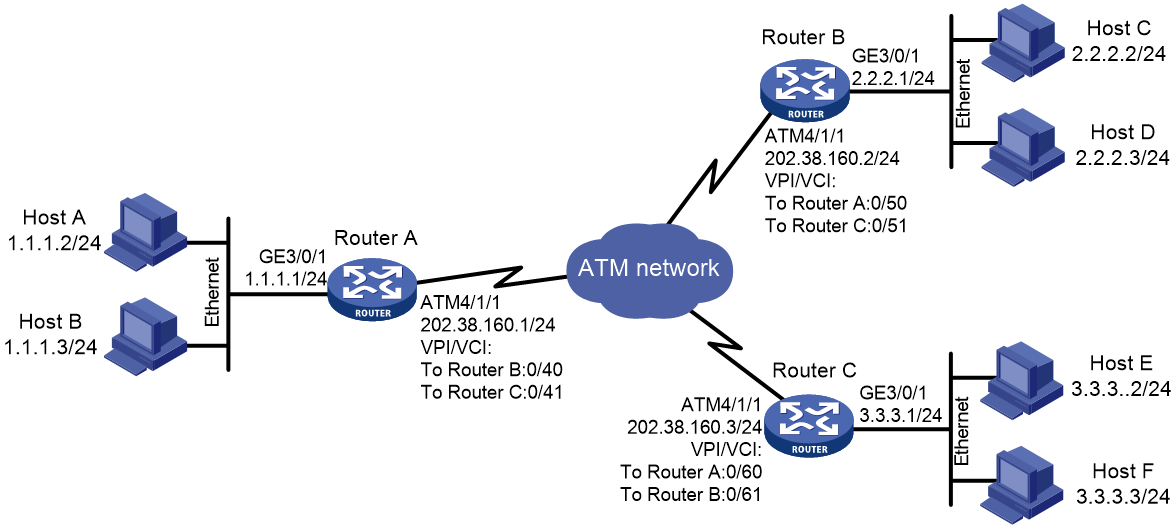
As shown in Figure 1, Router A is the egress gateway for the headquarters of an enterprise. Router B and Router C are egress gateways for the branch sites of the enterprise. Configure IPoA for communication among the three LANs across an ATM network.
Analysis
To enable the upper-layer protocols to find a remote device by its IP address, map the IP address of the remote device to the local PVC.
Restrictions and guidelines
When you configure IPoA, follow these restrictions and guidelines:
· ATM interfaces support only manually created permanent virtual circuits (PVCs), not switched virtual circuits (SVCs) created through the exchange of signals.
· You can configure only one PVC for an ATM P2P subinterface.
· Only one IP address can be mapped to a PVC. From the static IP mapping, default mapping, or InARP mapping methods, you can choose only one IP mapping method.
· Different PVCs on the same interface cannot be mapped to the same IP address.
· The PVCs on the same interface can be configured with only one default mapping.
· If the interfaces of two routers are connected back-to-back, the local PVC mapped to the remote IP address must have the same VPI/VCI value as the remote PVC mapped to the local IP address.
Procedures
1. Configure Router A:
# Enter the view of interface ATM 4/1/1 and configure an IP address for it.
[RouterA] interface atm 4/1/1
[RouterA-ATM4/1/1] ip address 202.38.160.1 255.255.255.0
# Create PVCs, and enable them to carry IP.
[RouterA-ATM4/1/1] pvc to_b 0/40
[RouterA-ATM4/1/1-pvc-to_b-0/40] map ip 202.38.160.2
[RouterA-ATM4/1/1-pvc-to_b-0/40] quit
[RouterA-ATM4/1/1] pvc to_c 0/41
[RouterA-ATM4/1/1-pvc-to_c-0/41] map ip 202.38.160.3
2. Configure Router B:
# Enter the view of interface ATM 4/1/1 and configure an IP address for it.
[RouterB] interface atm 4/1/1
[RouterB-ATM4/1/1] ip address 202.38.160.2 255.255.255.0
# Create PVCs, and enable them to carry IP.
[RouterB-ATM4/1/1] pvc to_a 0/50
[RouterB-ATM4/1/1-pvc-to_a-0/50] map ip 202.38.160.1
[RouterB-ATM4/1/1-pvc-to_a-0/50] quit
[RouterB-ATM4/1/1] pvc to_c 0/51
[RouterB-ATM4/1/1-pvc-to_c-0/51] map ip 202.38.160.3
3. Configure Router C:
# Enter the view of interface ATM 4/1/1 and configure an IP address for it.
[RouterC] interface atm 4/1/1
[RouterC-ATM4/1/1] ip address 202.38.160.3 255.255.255.0
# Create PVCs, and enable them to carry IP.
[RouterC-ATM4/1/1] pvc to_a 0/60
[RouterC-ATM4/1/1-pvc-to_a-0/60] map ip 202.38.160.1
[RouterC-ATM4/1/1-pvc-to_a-0/60] quit
[RouterC-ATM4/1/1] pvc to_b 0/61
[RouterC-ATM4/1/1-pvc-to_b-0/61] map ip 202.38.160.2
Verifying the configuration
# Execute the display atm map-info command on Router A to verify that all PVCs are up.
<RouterA> display atm map-info
ATM4/1/1
PVC 0/40:
Protocol: IP, IP address: 202.38.160.2, State: UP
PVC 0/41:
Protocol: IP, IP address: 202.38.160.3, State: UP
# Use the ping command to verify that Router A and Router B can ping each other successfully.
Ping 202.38.160.2 (202.38.160.2): 56 data bytes, press CTRL_C to break
56 bytes from 202.38.160.2: icmp_seq=0 ttl=255 time=76.007 ms
56 bytes from 202.38.160.2: icmp_seq=1 ttl=255 time=8.790 ms
56 bytes from 202.38.160.2: icmp_seq=2 ttl=255 time=1.630 ms
56 bytes from 202.38.160.2: icmp_seq=3 ttl=255 time=0.841 ms
56 bytes from 202.38.160.2: icmp_seq=4 ttl=255 time=1.012 ms
--- Ping statistics for 202.38.160.2---
5 packets transmitted, 5 packets received, 0.0% packet loss
round-trip min/avg/max/std-dev = 0.841/17.656/76.007/29.326 ms
Configuration files
· Router A:
#
interface GigabitEthernet3/0/1
port link-mode route
ip address 1.1.1.1 255.255.255.0
#
interface ATM4/1/1
pvc to_b 0/40
map ip 202.38.160.2
pvc to_c 0/41
map ip 202.38.160.3
ip address 202.38.160.1 255.255.255.0
#
· Router B:
#
interface GigabitEthernet3/0/1
port link-mode route
ip address 2.2.2.1 255.255.255.0
#
interface ATM4/1/1
pvc to_a 0/50
map ip 202.38.160.1
pvc to_c 0/51
map ip 202.38.160.3
ip address 202.38.160.2 255.255.255.0
#
· Router C:
#
interface GigabitEthernet3/0/1
port link-mode route
ip address 3.3.3.1 255.255.255.0
#
interface ATM4/1/1
pvc to_a 0/60
map ip 202.38.160.1
pvc to_c 0/61
map ip 202.38.160.2
ip address 202.38.160.3 255.255.255.0
#
Related documentation
· H3C CR16000-F Routers Layer 2—WAN Access Command Reference-R7951P01
· H3C CR16000-F Routers Layer 2—WAN Access Configuration Guide-R7951P01
