- Related Documents
-
| Title | Size | Download |
|---|---|---|
| 01-H3C_IRF_Configuration_Examples | 174.11 KB |
|
|
|
H3C IRF Configuration Examples |
|
|
|
|
|
|
Software version: Release 7951P01
Document version: 6W100-20200625
Copyright © 2020 New H3C Technologies Co., Ltd. All rights reserved.
No part of this manual may be reproduced or transmitted in any form or by any means without prior written consent of New H3C Technologies Co., Ltd.
Except for the trademarks of New H3C Technologies Co., Ltd., any trademarks that may be mentioned in this document are the property of their respective owners.
The information in this document is subject to change without notice.
Contents
General restrictions and guidelines
Example: Setting up a LACP MAD-enabled IRF fabric
Verifying the link backup function of multichassis aggregations
Verifying the link backup function of IRF connections
Introduction
This document provides examples for deploying two-chassis IRF fabrics.
Prerequisites
The configuration examples in this document were created and verified in a lab environment, and all the devices were started with the factory default configuration. When you are working on a live network, make sure you understand the potential impact of every command on your network.
This document assumes that you have basic knowledge of H3C IRF.
General restrictions and guidelines
When you set up and configure an IRF fabric, follow the restrictions and guidelines in this section. For more information about IRF configuration restrictions and guidelines, see Virtual Technologies Configuration Guide for your devices.
Hardware compatibility with IRF
To establish an IRF fabric successfully, make sure the member device models, their IRF physical interfaces, and switching fabric modules meet the compatibility requirements in Table 1.
Table 1 Hardware compatibility matrix for IRF establishment
|
Hardware platform |
IRF members |
IRF physical interfaces |
Switching fabric module requirements |
|
CR16006-F CR16010-F CR16014-F |
Any combination of these router models. |
10-GE or 40-GE Ethernet fiber ports on CSPC cards except the following cards: · CSPC-GE16XP4L-E. · CSPC-GE24L-E. · CSPC-GP24GE8XP2L-E. |
Use either of the following schemes: · Use Type-A switching fabric modules across the entire IRF fabric. · Use Type-B and Type-D switching fabric modules. ¡ On a member device, use Type-B or Type-D modules, but not both. ¡ Different types of switching fabric modules can be used between member devices. |
|
CR16006-F CR16010-F CR16010H-F CR16014-F CR16018-F |
All members are the same model. |
10-GE, 40-GE, or 100-GE Ethernet fiber ports on CEPC cards or CSPEX cards except the following cards: · CSPEX-1204. · CSPEX-1104-E. · CSPEX-1512X. · CSPEX-1612X. · CSPEX-1812X. |
All member devices use same model switching fabric modules. |
MPU requirements for IRF
To form a CR16000-F IRF fabric, every member device must use the same model of MPUs.
Software requirements for IRF
All IRF member devices must run the same software image version. Make sure the software auto-update feature is enabled on all member devices.
IRF fabric size
An CR16000-F IRF fabric supports a maximum of two member devices.
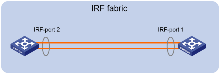
IRF port connection
When you connect neighboring IRF members, connect the physical interfaces of IRF-port 1 on one member to the physical interfaces of IRF-port 2 on the other (see Figure 1). On neighboring members, IRF ports with the same port index cannot have physical connections.
Figure 1 Connecting IRF physical interfaces
Example: Setting up a LACP MAD-enabled IRF fabric
Network configuration
As shown in Figure 2:
· Use Device A and Device B to set up an IRF fabric at the core layer of the network.
· Use multichassis link aggregations to connect the IRF fabric to the access switches and the upstream egress routers.
· Use LACP MAD to detect IRF split.
· Run OSPF between the IRF fabric and the egress routers.
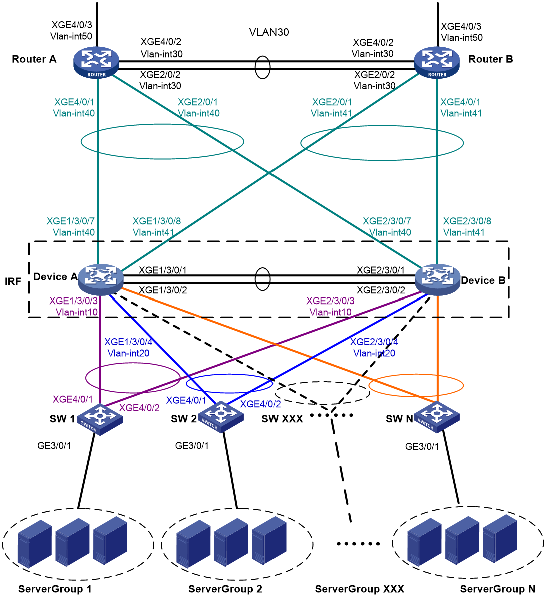
Table 2 VLAN and IP address assignment
|
Device |
VLAN interface |
IP address |
|
Router A |
VLAN-interface 30 |
172.24.2.2/24 |
|
VLAN-interface 40 |
172.24.40.2/24 |
|
|
VLAN-interface 50 |
172.24.1.2/24 |
|
|
Router B |
VLAN-interface 30 |
172.24.2.3/24 |
|
VLAN-interface 41 |
172.24.41.3/24 |
|
|
VLAN-interface 50 |
172.24.4.2/24 |
|
|
IRF fabric |
VLAN-interface 10 |
172.24.10.254/24 |
|
VLAN-interface 20 |
172.24.20.254/24 |
|
|
VLAN-interface 40 |
172.24.40.254/24 |
|
|
VLAN-interface 41 |
172.24.41.254/24 |
Analysis
For LACP MAD to run correctly, ensure that the intermediate device (SW 1 in this example) supports extended LACPDUs for LACP MAD.
To avoid single points of failure, use multichassis link aggregations to connect the IRF fabric to the downstream and upstream devices.
You do not need to run LACP MAD on all link aggregations. You can detect IRF split effectively by running LACP MAD on one dynamic link aggregation.
Procedures
Setting up the IRF fabric
1. Configure Device A:
# Assign member ID 1 to Device A.
<DeviceA> system-view
[DeviceA] irf member 1
# Bind Ten-GigabitEthernet 3/0/1 and Ten-GigabitEthernet 3/0/2 to IRF-port 2.
[DeviceA] interface ten-gigabitethernet 3/0/1
[DeviceA-Ten-GigabitEthernet3/0/1] port link-mode bridge
[DeviceA-Ten-GigabitEthernet3/0/1] quit
[DeviceA] interface ten-gigabitethernet 3/0/2
[DeviceA-Ten-GigabitEthernet3/0/2] port link-mode bridge
[DeviceA-Ten-GigabitEthernet3/0/2] quit
[DeviceA] irf-port 2
[DeviceA-irf-port2] port group interface ten-gigabitethernet 3/0/1
[DeviceA-irf-port2] port group interface ten-gigabitethernet 3/0/2
[DeviceA-irf-port2] quit
# Save the running configuration to the main next-startup configuration file before changing the operating mode to IRF.
|
|
IMPORTANT: IRF mode change requires a system reboot. This step prevents the loss of unsaved settings upon system reboot. |
[DeviceA] save
# Enable IRF mode.
[DeviceA] chassis convert mode irf
The device will switch to IRF mode and reboot.
You are recommended to save the current running configuration and specify the configuration file for the next startup. Continue? [Y/N]:y
Do you want to convert the content of the next startup configuration file cfa0:/
irf.cfg to make it available in stack mode? [Y/N]:y
Now rebooting, please wait...
2. Configure Device B:
# Assign member ID 2 to Device B.
<DeviceB> system-view
[DeviceB] irf member 2
# Bind Ten-GigabitEthernet 3/0/1 and Ten-GigabitEthernet 3/0/2 to IRF-port 1.
[DeviceB] interface ten-gigabitethernet 3/0/1
[DeviceB-Ten-GigabitEthernet3/0/1] port link-mode bridge
[DeviceB-Ten-GigabitEthernet3/0/1] quit
[DeviceB] interface ten-gigabitethernet 3/0/2
[DeviceB-Ten-GigabitEthernet3/0/2] port link-mode bridge
[DeviceB-Ten-GigabitEthernet3/0/2] quit
[DeviceB] irf-port 1
[DeviceB-irf-port1] port group interface ten-gigabitethernet 3/0/1
[DeviceB-irf-port1] port group interface ten-gigabitethernet 3/0/2
[DeviceB-irf-port1] quit
# Save the configuration.
[DeviceB] save
# Connect the physical interfaces of IRF-port 2 on Device A to the physical interfaces of IRF-port 1 on Device B, as shown in Figure 2. (Details not shown.)
# Enable IRF mode.
[DeviceB] chassis convert mode irf
The device will switch to IRF mode and reboot.
You are recommended to save the current running configuration and specify the configuration file for the next startup. Continue? [Y/N]:y
Do you want to convert the content of the next startup configuration file cfa0:/
irf.cfg to make it available in stack mode? [Y/N]:y
Now rebooting, please wait...
Configuring software features
This example provides only basic software feature configuration.
Configuring the IRF fabric
After the IRF fabric is formed, the master's system name becomes the fabric's system name. You can configure software features on the fabric as you do on a standalone device.
1. Configure link aggregations:
# Create Layer 2 aggregate interface Bridge-Aggregation 1, set its mode to dynamic, and enable LACP MAD on the aggregate interface.
<DeviceA> system-view
[DeviceA] interface bridge-aggregation 1
[DeviceA-Bridge-Aggregation1] link-aggregation mode dynamic
[DeviceA-Bridge-Aggregation1] mad enable
You need to assign a domain ID (range: 0-4294967295)
[Current domain is: 0]:
The assigned domain ID is: 0
MAD LACP only enable on dynamic aggregation interface.
[DeviceA-Bridge-Aggregation1] quit
# Assign the downlink ports that connect to SW 1 to the aggregation group of Bridge-Aggregation 1.
[DeviceA] interface ten-gigabitethernet 1/3/0/3
[DeviceA-Ten-GigabitEthernet1/3/0/3] port link-mode bridge
[DeviceA-Ten-GigabitEthernet1/3/0/3] port link-aggregation group 1
[DeviceA-Ten-GigabitEthernet1/3/0/3] quit
[DeviceA] interface ten-gigabitethernet 2/3/0/3
[DeviceA-Ten-GigabitEthernet2/3/0/3] port link-mode bridge
[DeviceA-Ten-GigabitEthernet2/3/0/3] port link-aggregation group 1
[DeviceA-Ten-GigabitEthernet2/3/0/3] quit
# Create Bridge-Aggregation 2 and assign the downlink ports that connect to SW 2 to the aggregation group.
[DeviceA] interface bridge-aggregation 2
[DeviceA-Bridge-Aggregation2] quit
[DeviceA] interface ten-gigabitethernet 1/3/0/4
[DeviceA-Ten-GigabitEthernet1/3/0/4] port link-mode bridge
[DeviceA-Ten-GigabitEthernet1/3/0/4] port link-aggregation group 2
[DeviceA-Ten-GigabitEthernet1/3/0/4] quit
[DeviceA] interface ten-gigabitethernet 2/3/0/4
[DeviceA-Ten-GigabitEthernet2/3/0/4] port link-mode bridge
[DeviceA-Ten-GigabitEthernet2/3/0/4] port link-aggregation group 2
[DeviceA-Ten-GigabitEthernet2/3/0/4] quit
# Create Bridge-Aggregation 1023 and assign the uplink ports that connect to Router A to Bridge-Aggregation 1023.
[DeviceA] interface bridge-aggregation 1023
[DeviceA-Bridge-Aggregation1023] quit
[DeviceA] interface ten-gigabitethernet 1/3/0/7
[DeviceA-Ten-GigabitEthernet1/3/0/7] port link-mode bridge
[DeviceA-Ten-GigabitEthernet1/3/0/7] port link-aggregation group 1023
[DeviceA-Ten-GigabitEthernet1/3/0/7] quit
[DeviceA] interface ten-gigabitethernet 2/3/0/7
[DeviceA-Ten-GigabitEthernet2/3/0/7] port link-mode bridge
[DeviceA-Ten-GigabitEthernet2/3/0/7] port link-aggregation group 1023
[DeviceA-Ten-GigabitEthernet2/3/0/7] quit
# Create Bridge-Aggregation 1024 and assign the uplink ports that connect to Router B to Bridge-Aggregation 1024.
[DeviceA] interface bridge-aggregation 1024
[DeviceA-Bridge-Aggregation1024] quit
[DeviceA] interface ten-gigabitethernet 1/3/0/8
[DeviceA-Ten-GigabitEthernet1/3/0/8] port link-mode bridge
[DeviceA-Ten-GigabitEthernet1/3/0/8] port link-aggregation group 1024
[DeviceA-Ten-GigabitEthernet1/3/0/8] quit
[DeviceA] interface ten-gigabitethernet 2/3/0/8
[DeviceA-Ten-GigabitEthernet2/3/0/8] port link-mode bridge
[DeviceA-Ten-GigabitEthernet2/3/0/8] port link-aggregation group 1024
[DeviceA-Ten-GigabitEthernet2/3/0/8] quit
2. Configure VLAN, IP address, and routing settings:
# Create VLAN 10, assign an IP address to VLAN-interface 10, and assign Bridge-Aggregation 1 (the interface connected to SW 1) to VLAN 10.
[DeviceA] vlan 10
[DeviceA-vlan10] quit
[DeviceA] interface vlan-interface 10
[DeviceA-Vlan-interface10] ip address 172.24.10.254 24
[DeviceA-Vlan-interface10] quit
[DeviceA] interface bridge-aggregation 1
[DeviceA-Bridge-Aggregation1] port link-type trunk
[DeviceA-Bridge-Aggregation1] undo port trunk permit vlan 1
[DeviceA-Bridge-Aggregation1] port trunk permit vlan 10
[DeviceA-Bridge-Aggregation1] quit
# Create VLAN 20, assign an IP address to VLAN-interface 20, and assign Bridge-Aggregation 2 (the interface connected to SW 2) to VLAN 20.
[DeviceA] vlan 20
[DeviceA-vlan20] quit
[DeviceA] interface vlan-interface 20
[DeviceA-Vlan-interface20] ip address 172.24.20.254 24
[DeviceA-Vlan-interface20] quit
[DeviceA] interface bridge-aggregation 2
[DeviceA-Bridge-Aggregation2] port link-type trunk
[DeviceA-Bridge-Aggregation2] undo port trunk permit vlan 1
[DeviceA-Bridge-Aggregation2] port trunk permit vlan 20
[DeviceA-Bridge-Aggregation2] quit
# Create VLAN 40, assign an IP address to VLAN-interface 40, and assign Bridge-Aggregation 1023 (the interface connected to Router A) to VLAN 40.
[DeviceA] vlan 40
[DeviceA-vlan40] quit
[DeviceA] interface vlan-interface 40
[DeviceA-Vlan-interface40] ip address 172.24.40.254 24
[DeviceA-Vlan-interface40] quit
[DeviceA] interface bridge-aggregation 1023
[DeviceA-Bridge-Aggregation1023] port access vlan 40
[DeviceA-Bridge-Aggregation1023] quit
# Create VLAN 41, assign an IP address to VLAN-interface 41, and assign Bridge-Aggregation 1024 (the interface connected to Router B) to VLAN 41.
[DeviceA] vlan 41
[DeviceA-vlan41] quit
[DeviceA] interface vlan-interface 41
[DeviceA-Vlan-interface41] ip address 172.24.41.254 24
[DeviceA-Vlan-interface41] quit
[DeviceA] interface bridge-aggregation 1024
[DeviceA-Bridge-Aggregation1024] port access vlan 41
[DeviceA-Bridge-Aggregation1024] quit
3. Configure OSPF between the IRF fabric and the egress routers.
[DeviceA] ospf
[DeviceA-ospf-1] import-route direct
[DeviceA-ospf-1] area 0
[DeviceA-ospf-1-area-0.0.0.0] network 172.24.40.0 0.0.0.255
[DeviceA-ospf-1-area-0.0.0.0] network 172.24.41.0 0.0.0.255
[DeviceA-ospf-1-area-0.0.0.0] quit
[DeviceA-ospf-1] quit
Configuring SW 1
1. Configure a link aggregation:
# Create Bridge-Aggregation 1 and enable the dynamic aggregation mode. You must enable the dynamic aggregation mode because this link aggregation will be used for LACP MAD.
<SW1> system-view
[SW1] interface bridge-aggregation 1
[SW1-Bridge-Aggregation1] link-aggregation mode dynamic
[SW1-Bridge-Aggregation1] quit
# Assign the uplink ports that connect to the IRF fabric to Bridge-Aggregation 1.
[SW1] interface ten-gigabitethernet 4/0/1
[SW1-Ten-GigabitEthernet4/0/1] port link-aggregation group 1
[SW1-Ten-GigabitEthernet4/0/1] quit
[SW1] interface ten-gigabitethernet 4/0/2
[SW1-Ten-GigabitEthernet4/0/2] port link-aggregation group 1
[SW1-Ten-GigabitEthernet4/0/2] quit
2. Configure VLAN settings:
# Create all VLANs.
[SW1] vlan all
# Configure VLAN settings on the uplink aggregate interface that connects to the IRF fabric.
[SW1] interface bridge-aggregation 1
[SW1-Bridge-Aggregation1] port link-type trunk
[SW1-Bridge-Aggregation1] undo port trunk permit vlan 1
[SW1-Bridge-Aggregation1] port trunk permit vlan 10
[SW1-Bridge-Aggregation1] quit
# Configure VLAN settings on the port that connects to Server Group 1.
[SW1] interface gigabitethernet 3/0/1
[SW1-GigabitEthernet3/0/1] port link-type trunk
[SW1-GigabitEthernet3/0/1] port trunk permit vlan all
[SW1-GigabitEthernet3/0/1] undo port trunk permit vlan 1
[SW1-GigabitEthernet3/0/1] quit
Configuring SW 2
1. Configure a link aggregation:
# Create Bridge-Aggregation 1.
<SW2>system-view
[SW2] interface bridge-aggregation 1
[SW2-Bridge-Aggregation1] quit
# Assign the uplink ports that connect to the IRF fabric to Bridge-Aggregation 1.
[SW2] interface ten-gigabitethernet 4/0/1
[SW2-Ten-GigabitEthernet4/0/1] port link-aggregation group 1
[SW2-Ten-GigabitEthernet4/0/1] quit
[SW2] interface ten-gigabitethernet 4/0/2
[SW2-Ten-GigabitEthernet4/0/2] port link-aggregation group 1
[SW2-Ten-GigabitEthernet4/0/2] quit
2. Configure VLAN settings:
# Create all VLANs.
[SW2] vlan all
# Configure VLAN settings on the uplink aggregate interface that connects to the IRF fabric.
[SW2] interface bridge-aggregation 1
[SW2-Bridge-Aggregation1] port link-type trunk
[SW2-Bridge-Aggregation1] undo port trunk permit vlan 1
[SW2-Bridge-Aggregation1] port trunk permit vlan 20
[SW2-Bridge-Aggregation1] quit
# Configure VLAN settings on the port that connects to Server Group 2.
[SW2] interface gigabitethernet 3/0/1
[SW2-GigabitEthernet3/0/1] port link-type trunk
[SW2-GigabitEthernet3/0/1] port trunk permit vlan all
[SW2-GigabitEthernet3/0/1] undo port trunk permit vlan 1
[SW2-GigabitEthernet3/0/1] quit
Configuring Router A
This example provides only settings for connectivity to the IRF fabric. Settings for external connectivity are beyond the scope of this example.
1. Configure link aggregations:
# Create Bridge-Aggregation 1 and assign the downlink ports that connect to the IRF fabric to Bridge-Aggregation 1.
<RouterA> system-view
[RouterA] interface bridge-aggregation 1
[RouterA-Bridge-Aggregation1] quit
[RouterA] interface ten-gigabitethernet 4/0/1
[RouterA-Ten-GigabitEthernet4/0/1] port link-mode bridge
[RouterA-Ten-GigabitEthernet4/0/1] port link-aggregation group 1
[RouterA-Ten-GigabitEthernet4/0/1] quit
[RouterA] interface ten-gigabitethernet 2/0/1
[RouterA-Ten-GigabitEthernet2/0/1] port link-mode bridge
[RouterA-Ten-GigabitEthernet2/0/1] port link-aggregation group 1
[RouterA-Ten-GigabitEthernet2/0/1] quit
# Create Bridge-Aggregation 2 and assign the ports that connect to Router B to Bridge-Aggregation 2.
[RouterA] interface bridge-aggregation 2
[RouterA-Bridge-Aggregation2] quit
[RouterA] interface ten-gigabitethernet 4/0/2
[RouterA-Ten-GigabitEthernet4/0/2] port link-mode bridge
[RouterA-Ten-GigabitEthernet4/0/2] port link-aggregation group 2
[RouterA-Ten-GigabitEthernet4/0/2] quit
[RouterA] interface ten-gigabitethernet 2/0/2
[RouterA-Ten-GigabitEthernet2/0/2] port link-mode bridge
[RouterA-Ten-GigabitEthernet2/0/2] port link-aggregation group 2
[RouterA-Ten-GigabitEthernet2/0/2] quit
2. Configure VLAN, IP address, and internal routing protocol settings:
# Create VLAN 40, assign an IP address to VLAN-interface 40, and assign Bridge-Aggregation 1 (the interface connected to the IRF fabric) to VLAN 40.
[RouterA] vlan 40
[RouterA-vlan40] quit
[RouterA] interface vlan-interface 40
[RouterA-vlan-interface40] ip address 172.24.40.2 24
[RouterA-vlan-interface40] quit
[RouterA] interface bridge-aggregation 1
[RouterA-Bridge-Aggregation1] port access vlan 40
[RouterA-Bridge-Aggregation1] quit
# Create VLAN 30, assign an IP address to VLAN-interface 30, and assign Bridge-Aggregation 2 (the interface connected to Router B) to VLAN 30.
[RouterA] vlan 30
[RouterA-vlan30] quit
[RouterA] interface vlan-interface 30
[RouterA-vlan-interface30] ip address 172.24.2.2 24
[RouterA-vlan-interface30] quit
[RouterA] interface bridge-aggregation 2
[RouterA-Bridge-Aggregation2] port link-type access
[RouterA-Bridge-Aggregation2] port access vlan 30
[RouterA-Bridge-Aggregation2] quit
# Create VLAN 50, assign an IP address to VLAN-interface 50, and assign Ten-GigabitEthernet 4/0/3 (the interface connected to the external network) to VLAN 50.
[RouterA] vlan 50
[RouterA-vlan50] quit
[RouterA] interface vlan-interface 50
[RouterA-vlan-interface50] ip address 172.24.1.2 24
[RouterA-vlan-interface50] quit
[RouterA] interface ten-gigabitethernet 4/0/3
[RouterA-Ten-GigabitEthernet4/0/3] port link-mode bridge
[RouterA-Ten-GigabitEthernet4/0/3] port access vlan 50
[RouterA-Ten-GigabitEthernet4/0/3] quit
3. Configure OSPF between Router A and the IRF fabric.
[RouterA] ospf
[RouterA-ospf-1] import-route direct
[RouterA-ospf-1] area 0
[RouterA-ospf-1-area-0.0.0.0] network 172.24.40.0 0.0.0.255
[RouterA-ospf-1-area-0.0.0.0] network 172.24.2.0 0.0.0.255
[RouterA-ospf-1-area-0.0.0.0] quit
[RouterA-ospf-1] quit
Configuring Router B
This example provides only settings for connectivity to the IRF fabric. Settings for external connectivity are beyond the scope of this example.
1. Configure link aggregations:
# Create Bridge-Aggregation 1 and assign the downlink ports that connect to the IRF fabric to Bridge-Aggregation 1.
<RouterB> system-view
[RouterB] interface bridge-aggregation 1
[RouterB-Bridge-Aggregation1] quit
[RouterB] interface ten-gigabitethernet 4/0/1
[RouterB-Ten-GigabitEthernet4/0/1] port link-mode bridge
[RouterB-Ten-GigabitEthernet4/0/1] port link-aggregation group 1
[RouterB-Ten-GigabitEthernet4/0/1] quit
[RouterB] interface ten-gigabitethernet 2/0/1
[RouterB-Ten-GigabitEthernet2/0/1] port link-mode bridge
[RouterB-Ten-GigabitEthernet2/0/1] port link-aggregation group 1
[RouterB-Ten-GigabitEthernet2/0/1] quit
# Create Bridge-Aggregation 2 and assign the ports that connect to Router A to Bridge-Aggregation 2.
[RouterB] interface bridge-aggregation 2
[RouterB-Bridge-Aggregation2] quit
[RouterB] interface ten-gigabitethernet 4/0/2
[RouterB-Ten-GigabitEthernet4/0/2] port link-mode bridge
[RouterB-Ten-GigabitEthernet4/0/2] port link-aggregation group 2
[RouterB-Ten-GigabitEthernet4/0/2] quit
[RouterB] interface ten-gigabitethernet 2/0/2
[RouterB-Ten-GigabitEthernet2/0/2] port link-mode bridge
[RouterB-Ten-GigabitEthernet2/0/2] port link-aggregation group 2
[RouterB-Ten-GigabitEthernet2/0/2] quit
2. Configure VLAN, IP address, and internal routing protocol settings:
# Create VLAN 41, assign an IP address to VLAN-interface 41, and assign Bridge-Aggregation 1 (the interface connected to the IRF fabric) to VLAN 41.
[RouterB] vlan 41
[RouterB-vlan41] quit
[RouterB] interface vlan-interface 41
[RouterB-vlan-interface41] ip address 172.24.41.3 24
[RouterB-vlan-interface41] quit
[RouterB] interface bridge-aggregation 1
[RouterB-Bridge-Aggregation1] port access vlan 41
[RouterB-Bridge-Aggregation1] quit
# Create VLAN 30, assign an IP address to VLAN-interface 30, and assign Bridge-Aggregation 2 (the interface connected to Router A) to VLAN 30.
[RouterB] vlan 30
[RouterB-vlan30] quit
[RouterB] interface vlan-interface 30
[RouterB-vlan-interface30] ip address 172.24.2.3 24
[RouterB-vlan-interface30] quit
[RouterB] interface bridge-aggregation 2
[RouterB-Bridge-Aggregation2] port link-type access
[RouterB-Bridge-Aggregation2] port access vlan 30
[RouterB-Bridge-Aggregation2] quit
# Create VLAN 50, assign an IP address to VLAN-interface 50, and assign Ten-GigabitEthernet 4/0/3 (the interface connected to the external network) to VLAN 50.
[RouterB] vlan 50
[RouterB-vlan50] quit
[RouterB] interface vlan-interface 50
[RouterB-vlan-interface50] ip address 172.24.4.3 24
[RouterB-vlan-interface50] quit
[RouterB] interface ten-gigabitethernet 4/0/3
[RouterB-Ten-GigabitEthernet4/0/3] port link-mode bridge
[RouterB-Ten-GigabitEthernet4/0/3] port access vlan 50
[RouterB-Ten-GigabitEthernet4/0/3] quit
3. Configure OSPF between Router B and the IRF fabric.
[RouterB] ospf
[RouterB-ospf-1] import-route direct
[RouterB-ospf-1] area 0
[RouterB-ospf-1-area-0.0.0.0] network 172.24.41.0 0.0.0.255
[RouterB-ospf-1-area-0.0.0.0] network 172.24.2.0 0.0.0.255
[RouterB-ospf-1-area-0.0.0.0] quit
[RouterB-ospf-1] quit
Verifying the configuration
Verifying the IRF function
# Verify that the IRF fabric has been established.
[DeviceA] display irf
MemberID Slot Role Priority CPU-Mac Description
*+1 0 Master 1 0210-fc01-0000 ---
2 0 Standby 1 0210-fc02-0000 ---
--------------------------------------------------
* indicates the device is the master.
+ indicates the device through which the user logs in.
The Bridge MAC of the IRF is: 3822-d60f-2800
Auto upgrade : yes
Mac persistent : always
Domain ID : 0
Auto merge : yes
Verifying the link backup function of multichassis aggregations
# Shut down Ten-GigabitEthernet 1/3/0/8, the port connected to the egress router.
[DeviceA] interface ten-gigabitethernet 1/3/0/8
[DeviceA-Ten-GigabitEthernet1/3/0/8] shutdown
# Ping an IP address on the public network from a PC in Server Group 1.
C:\Users>ping 202.108.22.5 -t
Pinging 202.108.22.5 with 32 bytes of data:
Reply from 202.108.22.5: bytes=32 time=1ms TTL=122
Reply from 202.108.22.5: bytes=32 time=13ms TTL=122
Reply from 202.108.22.5: bytes=32 time<1ms TTL=122
Request timed out.
Request timed out.
Request timed out.
Reply from 202.108.22.5: bytes=32 time<1ms TTL=122
Reply from 202.108.22.5: bytes=32 time<1ms TTL=122
Reply from 202.108.22.5: bytes=32 time<1ms TTL=122
The output shows that the address can be pinged after transient traffic disruption.
# Bring up Ten-GigabitEthernet 1/3/0/8 and shut down Ten-GigabitEthernet 2/3/0/8.
[DeviceA-Ten-GigabitEthernet1/3/0/8] undo shutdown
[DeviceA-Ten-GigabitEthernet1/3/0/8] quit
[DeviceA] interface ten-gigabitethernet 2/3/0/8
[DeviceA-Ten-GigabitEthernet2/3/0/8] shutdown
# Ping the IP address on the public network from the PC.
C:\Users>ping 202.108.22.5 -t
Pinging 202.108.22.5 with 32 bytes of data:
Reply from 202.108.22.5: bytes=32 time=1ms TTL=122
Reply from 202.108.22.5: bytes=32 time=13ms TTL=122
Reply from 202.108.22.5: bytes=32 time<1ms TTL=122
Request timed out.
Request timed out.
Request timed out.
Reply from 202.108.22.5: bytes=32 time<1ms TTL=122
Reply from 202.108.22.5: bytes=32 time<1ms TTL=122
Reply from 202.108.22.5: bytes=32 time<1ms TTL=122
The output shows that the address can be pinged after transient traffic disruption.
Verifying the link backup function of IRF connections
# Verify that the IRF fabric does not split and can forward traffic across member chassis after one IRF connection cable is removed. (Details not shown.)
Configuration files
· IRF fabric:
#
irf mac-address persistent always
irf auto-update enable
irf auto-merge enable
undo irf link-delay
irf member 1 priority 1
irf member 2 priority 1
#
ospf 1
import-route direct
area 0.0.0.0
network 172.24.40.0 0.0.0.255
network 172.24.41.0 0.0.0.255
#
vlan 10
#
vlan 20
#
vlan 40
#
vlan 41
#
irf-port 1/2
port group interface Ten-GigabitEthernet1/3/0/1 mode enhanced
port group interface Ten-GigabitEthernet1/3/0/2 mode enhanced
#
irf-port 2/1
port group interface Ten-GigabitEthernet2/3/0/1 mode enhanced
port group interface Ten-GigabitEthernet2/3/0/2 mode enhanced
#
interface bridge-aggregation 1
port link-type trunk
undo port trunk permit vlan 1
port trunk permit vlan 10
link-aggregation mode dynamic
mad enable
#
interface bridge-aggregation 2
port link-type trunk
undo port trunk permit vlan 1
port trunk permit vlan 20
#
interface bridge-aggregation 1023
port access vlan 40
#
interface bridge-aggregation 1024
port access vlan 41
#
interface vlan-interface 10
ip address 172.24.10.254 255.255.255.0
#
interface vlan-interface 20
ip address 172.24.20.254 255.255.255.0
#
interface vlan-interface 40
ip address 172.24.40.254 255.255.255.0
#
interface vlan-interface 41
ip address 172.24.41.254 255.255.255.0
#
interface Ten-GigabitEthernet 1/3/0/3
port link-mode bridge
port link-type trunk
undo port trunk permit vlan 1
port trunk permit vlan 10
port link-aggregation group 1
#
interface Ten-GigabitEthernet 1/3/0/4
port link-mode bridge
port link-type trunk
undo port trunk permit vlan 1
port trunk permit vlan 20
port link-aggregation group 2
#
interface Ten-GigabitEthernet 1/3/0/7
port link-mode bridge
port access vlan 40
port link-aggregation group 1023
#
interface Ten-GigabitEthernet 1/3/0/8
port link-mode bridge
port access vlan 41
port link-aggregation group 1024
#
interface Ten-GigabitEthernet 2/3/0/3
port link-mode bridge
port link-type trunk
undo port trunk permit vlan 1
port trunk permit vlan 10
port link-aggregation group 1
#
interface Ten-GigabitEthernet 2/3/0/4
port link-mode bridge
port link-type trunk
undo port trunk permit vlan 1
port trunk permit vlan 20
port link-aggregation group 2
#
interface Ten-GigabitEthernet 2/3/0/7
port link-mode bridge
port access vlan 40
port link-aggregation group 1023
#
interface Ten-GigabitEthernet 2/3/0/8
port link-mode bridge
port access vlan 41
port link-aggregation group 1024
#
· SW 1:
#
vlan 10
#
interface Bridge-Aggregation 1
port link-type trunk
undo port trunk permit vlan 1
port trunk permit vlan 10
link-aggregation mode dynamic
#
interface GigabitEthernet 3/0/1
port link-mode bridge
port link-type trunk
undo port trunk permit vlan 1
port trunk permit vlan 2 to 4093
#
interface Ten-GigabitEthernet 4/0/1
port link-mode bridge
port link-type trunk
undo port trunk permit vlan 1
port trunk permit vlan 10
port link-aggregation group 1
#
interface Ten-GigabitEthernet 4/0/2
port link-mode bridge
port link-type trunk
undo port trunk permit vlan 1
port trunk permit vlan 10
port link-aggregation group 1
#
· SW 2:
#
vlan 20
#
interface Bridge-Aggregation 1
port link-type trunk
undo port trunk permit vlan 1
port trunk permit vlan 20
#
interface GigabitEthernet 3/0/1
port link-mode bridge
port link-type trunk
undo port trunk permit vlan 1
port trunk permit vlan 2 to 4093
#
interface Ten-GigabitEthernet 4/0/1
port link-mode bridge
port link-type trunk
undo port trunk permit vlan 1
port trunk permit vlan 20
port link-aggregation group 1
#
interface Ten-GigabitEthernet 4/0/2
port link-mode bridge
port link-type trunk
undo port trunk permit vlan 1
port trunk permit vlan 20
port link-aggregation group 1
#
· Router A:
#
ospf 1
import-route direct
area 0.0.0.0
network 172.24.2.0 0.0.0.255
network 172.24.40.0 0.0.0.255
#
vlan 30
#
vlan 40
#
vlan 50
#
interface bridge-aggregation 1
port access vlan 40
#
interface bridge-aggregation 2
port access vlan 30
#
interface vlan-interface 30
ip address 172.24.2.2 255.255.255.0
#
interface vlan-interface 40
ip address 172.24.40.2 255.255.255.0
#
interface vlan-interface 50
ip address 172.24.1.2 255.255.255.0
#
interface Ten-GigabitEthernet 2/0/1
port link-mode bridge
port access vlan 40
port link-aggregation group 1
#
interface Ten-GigabitEthernet 2/0/2
port link-mode bridge
port access vlan 30
port link-aggregation group 2
#
interface Ten-GigabitEthernet 4/0/1
port link-mode bridge
port access vlan 40
port link-aggregation group 1
#
interface Ten-GigabitEthernet 4/0/2
port link-mode bridge
port access vlan 30
port link-aggregation group 2
#
interface Ten-GigabitEthernet 4/0/3
port link-mode bridge
port access vlan 50
#
· Router B:
#
ospf 1
import-route direct
area 0.0.0.0
network 172.24.2.0 0.0.0.255
network 172.24.41.0 0.0.0.255
#
vlan 30
#
vlan 41
#
vlan 50
#
interface bridge-aggregation 1
port access vlan 41
#
interface bridge-aggregation 2
port access vlan 30
#
interface vlan-interface 30
ip address 172.24.2.3 255.255.255.0
#
interface vlan-interface 41
ip address 172.24.41.3 255.255.255.0
#
interface vlan-interface 50
ip address 172.24.4.3 255.255.255.0
#
interface Ten-GigabitEthernet 2/0/1
port link-mode bridge
port access vlan 41
port link-aggregation group 1
#
interface Ten-GigabitEthernet 2/0/2
port link-mode bridge
port access vlan 30
port link-aggregation group 2
#
interface Ten-GigabitEthernet 4/0/1
port link-mode bridge
port access vlan 41
port link-aggregation group 1
#
interface Ten-GigabitEthernet 4/0/2
port link-mode bridge
port access vlan 30
port link-aggregation group 2
#
interface Ten-GigabitEthernet 4/0/3
port link-mode bridge
port access vlan 50
#
Related documentation
· H3C CR16000-F Routers Virtual Technologies Command Reference-R7951P01
· H3C CR16000-F Routers Virtual Technologies Configuration Guide-R7951P01
