- Table of Contents
-
- 10-Security Configuration Guide
- 00-Preface
- 01-AAA configuration
- 02-802.1X configuration
- 03-MAC authentication configuration
- 04-Portal configuration
- 05-Port security configuration
- 06-Password control configuration
- 07-Keychain configuration
- 08-Public key management
- 09-PKI configuration
- 10-IPsec configuration
- 11-SSH configuration
- 12-SSL configuration
- 13-Attack detection and prevention configuration
- 14-TCP attack prevention configuration
- 15-IP source guard configuration
- 16-ARP attack protection configuration
- 17-ND attack defense configuration
- 18-uRPF configuration
- 19-MFF configuration
- 20-FIPS configuration
- 21-MACsec configuration
- 22-802.1X client configuration
- 23-Web authentication configuration
- 24-Object group configuration
- 25-Triple authentication configuration
- Related Documents
-
| Title | Size | Download |
|---|---|---|
| 15-IP source guard configuration | 189.54 KB |
Configuration restrictions and guidelines
Configuring the IPv4SG feature
Enabling IPv4SG on an interface
Configuring a static IPv4SG binding
Excluding IPv4 packets from IPSG filtering
Configuring the IPv6SG feature
Enabling IPv6SG on an interface
Configuring a static IPv6SG binding
Displaying and maintaining IPSG
Static IPv4SG configuration example
Dynamic IPv4SG using DHCP snooping configuration example
Dynamic IPv4SG using DHCP relay agent configuration example
Static IPv6SG configuration example
Dynamic IPv6SG using DHCPv6 snooping configuration example
Dynamic IPv6SG using DHCPv6 relay agent configuration example
Configuring IP source guard
Overview
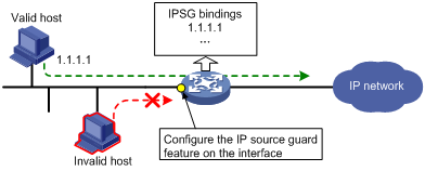
IP source guard (IPSG) prevents spoofing attacks by using an IPSG binding table to match legitimate packets. It drops packets that do not match the table. IPSG is a per-interface packet filter. Configuring the feature on one interface does not affect packet forwarding on another interface.
The IPSG binding table can include global and interface-specific bindings. IPSG first uses the interface-specific bindings to match packets. If no match is found, IPSG uses the global bindings. The IPSG bindings fall into the following types:
· IP.
· MAC.
· IP-MAC.
IPSG bindings can be static or dynamic.
· Static bindings—Configured manually. Global IPSG supports only static IP-MAC bindings. For more information about global static IPSG bindings, see "Static IPSG bindings."
· Dynamic bindings—Generated based on information from other modules. For more information about dynamic bindings, see "Dynamic IPSG bindings."
As shown in Figure 1, IPSG forwards only the packets that match an IPSG binding.
Figure 1 IPSG application
Static IPSG bindings
Static IPSG bindings are configured manually. They are suitable for scenarios where few hosts exist on a LAN and their IP addresses are manually configured. For example, you can configure a static IPSG binding on an interface that connects to a server. This binding allows the interface to receive packets only from the server.
Static IPSG bindings on an interface implement the following functions:
· Filter incoming IPv4 or IPv6 packets on the interface.
· Cooperate with ARP attack detection in IPv4 and ND attack detection in IPv6 for user validity checking.
For information about ARP attack detection, see "Configuring ARP attack protection." For information about ND attack detection, see "Configuring ND attack defense."
Static IPSG bindings can be global or interface-specific.
· Global static binding—Binds the IP address and MAC address in system view. The binding takes effect on all interfaces to filter packets for user spoofing attack prevention.
· Interface-specific static binding—Binds the IP address, MAC address, or any combination of the items in interface view. The binding takes effect only on the interface to check the validity of users who are attempting to access the interface.
Dynamic IPSG bindings
IPSG automatically obtains user information from other modules to generate dynamic bindings. The source modules include ARP snooping, 802.1X, DHCP relay agent, DHCPv6 relay agent, DHCP snooping, DHCPv6 snooping, DHCP server, and ND snooping.
For example, DHCP-based IPSG bindings are suitable for scenarios where hosts on a LAN obtain IP addresses through DHCP. IPSG is configured on the DHCP server, the DHCP snooping device, or the DHCP relay agent. It generates dynamic bindings based on the client bindings on the DHCP server, the DHCP snooping entries, or the DHCP relay entries. IPSG allows only packets from the DHCP clients to pass through.
Dynamic IPv4SG
Dynamic bindings generated based on different source modules are for different usages:
|
Interface types |
Source modules |
Binding usage |
|
Layer 2 Ethernet interface Layer 2 aggregate interface |
DHCP snooping ARP snooping |
Packet filtering. |
|
802.1X |
For cooperation with modules to provide security services. |
|
|
Layer 3 Ethernet interface VLAN interface |
DHCP relay agent |
Packet filtering. |
|
DHCP server |
For cooperation with modules (such as the authorized ARP module) to provide security services. |
|
|
ARP flood suppression |
Reporting bindings to the controller to provide online and offline user information. |
For more information about 802.1X, see "Configuring 802.1X." For information about ARP snooping, see Layer 3—IP Services Configuration Guide. For more information about ARP flood suppression, see VXLAN Configuration Guide. For more information about DHCP snooping, DHCP relay, and DHCP server, see Layer 3—IP Services Configuration Guide.
Dynamic IPv6SG
Dynamic IPv6SG bindings generated based on the following source modules are for packet filtering:
|
Interface types |
Source modules |
Binding usage |
|
Layer 2 Ethernet interface |
DHCPv6 snooping ND snooping |
Packet filtering. |
|
802.1X |
For cooperation with modules to provide security services. |
|
|
Layer 3 Ethernet interface VLAN interface |
DHCPv6 relay agent ND RA prefix entry recording |
Packet filtering. |
|
ND flood suppression DHCPv6 server |
Reporting bindings to the controller to provide online and offline user information. |
For more information about 802.1X, see "Configuring 802.1X." For more information about DHCPv6 snooping, ND snooping, DHCPv6 relay agent, DHCPv6 server, and ND RA prefix entry recording, see Layer 3—IP Services Configuration Guide. For more information about ND flood suppression, see VXLAN Configuration Guide.
Configuration restrictions and guidelines
Layer 3 Ethernet subinterfaces do not support enabling the IPSG feature or configuring static IPSG bindings.
In an IRF 3.1 system, do not configure IPSG on PEXs.
IPSG configuration task list
To configure IPv4SG, perform the following tasks:
|
Tasks at a glance |
|
(Required.) Enabling IPv4SG on an interface |
|
(Optional.) Configuring a static IPv4SG binding |
|
(Optional.) Excluding IPv4 packets from IPSG filtering |
To configure IPv6SG, perform the following tasks:
|
Tasks at a glance |
|
(Required.) Enabling IPv6SG on an interface |
|
(Optional.) Configuring a static IPv6SG binding |
Configuring the IPv4SG feature
You cannot configure the IPv4SG feature on a service loopback interface. If IPv4SG is enabled on an interface, you cannot assign the interface to a service loopback group.
Enabling IPv4SG on an interface
When you enable IPSG on an interface, the static and dynamic IPSG are both enabled.
· Static IPv4SG uses static bindings configured by using the ip source binding command.
· Dynamic IPv4SG generates dynamic bindings from related source modules. IPv4SG uses the bindings to filter incoming IPv4 packets based on the matching criteria specified in the ip verify source command.
To implement dynamic IPv4SG, make sure ARP snooping, DHCP snooping, DHCP relay agent, or DHCP server operates correctly on the network.
To enable the IPv4SG feature on an interface:
|
Step |
Command |
Remarks |
|
1. Enter system view. |
system-view |
N/A |
|
2. Enter interface view. |
interface interface-type interface-number |
The following interface types are supported: · Layer 2 Ethernet interface. · Layer 2 aggregate interface. · Layer 3 Ethernet interface. · Layer 3 Ethernet subinterface. · Layer 3 aggregate interface. · Layer 3 aggregate subinterface. · VLAN interface. |
|
3. Enable the IPv4SG feature. |
ip verify source { ip-address | ip-address mac-address | mac-address } |
By default, the IPv4SG feature is disabled on an interface. If you configure this command on an interface multiple times, the most recent configuration takes effect. |
Configuring a static IPv4SG binding
You can configure global static and interface-specific static IPv4SG bindings.
Global static bindings take effect on all interfaces.
Interface-specific static bindings take priority over global static bindings. An interface first uses the static bindings on the interface to match packets. If no match is found, the interface uses the global bindings.
Configuring a global static IPv4SG binding
|
Step |
Command |
Remarks |
|
1. Enter system view. |
system-view |
N/A |
|
2. Configure a global static IPv4SG binding. |
ip source binding ip-address ip-address mac-address mac-address |
No global static IPv4SG bindings exist. |
Configuring a static IPv4SG binding on an interface
|
Step |
Command |
Remarks |
|
1. Enter system view. |
system-view |
N/A |
|
2. Enter interface view. |
interface interface-type interface-number |
The following interface types are supported: · Layer 2 Ethernet interface. · Layer 2 aggregate interface. · Layer 3 Ethernet interface. · Layer 3 Ethernet subinterface. · Layer 3 aggregate interface. · Layer 3 aggregate subinterface. · VLAN interface. |
|
3. Configure a static IPv4SG binding. |
ip source binding { ip-address ip-address | ip-address ip-address mac-address mac-address | mac-address mac-address } [ vlan vlan-id ] |
By default, no static IPv4SG bindings exist on an interface. The vlan vlan-id option is supported only in Layer 2 Ethernet interface view. To configure a static IPv4SG binding for the ARP attack detection feature, make sure the following conditions are met: · The ip-address ip-address option, the mac-address mac-address option, and the vlan vlan-id option must be specified. · ARP attack detection must be enabled for the specified VLAN. You can configure the same static IPv4SG binding on different interfaces. |
Excluding IPv4 packets from IPSG filtering
Typically, IPv4SG processes all incoming IPv4 packets and discards the packets that do not match IPSG bindings on an interface. This task excludes IPv4 packets with specific source items from IPSG filtering. You can specify source VLANs for IPSG filtering exemption in the current software version. All IPv4 packets from the specified VLANs are forwarded without being processed by IPSG.
To exclude IPv4 packets with the specified source items from IPSG filtering:
|
Step |
Command |
Remarks |
|
1. Enter system view. |
system-view |
N/A |
|
2. Exclude IPv4 packets with the specified source items from IPSG filtering. |
ip verify source exclude vlan start-vlan-id [ to end-vlan-id ] |
By default, no excluded source items are configured. You can execute this command multiple times to specify multiple excluded VLANs. The specified excluded VLANs cannot overlap. |
Configuring the IPv6SG feature
You cannot configure the IPv6SG feature on a service loopback interface. If IPv6SG is enabled on an interface, you cannot assign the interface to a service loopback group.
Enabling IPv6SG on an interface
When you enable IPv6SG on an interface, the static and dynamic IPv6SG are both enabled.
· Static IPv6SG uses static bindings configured by using the ipv6 source binding command.
· Dynamic IPv6SG generates dynamic bindings from related source modules. IPv6SG uses the bindings to filter incoming IPv6 packets based on the matching criteria specified in the ipv6 verify source command.
To implement dynamic IPv6SG, make sure DHCPv6 snooping, DHCPv6 relay agent, or ND snooping operates correctly on the network.
To enable the IPv6SG feature on an interface:
|
Step |
Command |
Remarks |
|
1. Enter system view. |
system-view |
N/A |
|
2. Enter interface view. |
interface interface-type interface-number |
The following interface types are supported: · Layer 2 Ethernet interface. · Layer 3 Ethernet interface. · Layer 3 Ethernet subinterface. · Layer 3 aggregate interface. · Layer 3 aggregate subinterface. · VLAN interface. |
|
3. Enable the IPv6SG feature. |
ipv6 verify source { ip-address | ip-address mac-address | mac-address } |
By default, the IPv6SG feature is disabled on an interface. If you configure this command on an interface multiple times, the most recent configuration takes effect. |
Configuring a static IPv6SG binding
You can configure global static and interface-specific static IPv6SG bindings.
Global static bindings take effect on all interfaces.
Interface-specific static bindings take priority over global static bindings. An interface first uses the static bindings on the interface to match packets. If no match is found, the interface uses the global bindings.
Configuring a global static IPv6SG binding
|
Step |
Command |
Remarks |
|
1. Enter system view. |
system-view |
N/A |
|
2. Configure a global static IPv6SG binding. |
ipv6 source binding ip-address ipv6-address mac-address mac-address |
No global static IPv6SG bindings exist. |
Configuring a static IPv6SG binding on an interface
|
Step |
Command |
Remarks |
|
1. Enter system view. |
system-view |
N/A |
|
2. Enter interface view. |
interface interface-type interface-number |
The following interface types are supported: · Layer 2 Ethernet interface. · Layer 3 Ethernet interface. · Layer 3 Ethernet subinterface. · Layer 3 aggregate interface. · Layer 3 aggregate subinterface. · VLAN interface. |
|
3. Configure a static IPv6SG binding. |
ipv6 source binding { ip-address ipv6-address | ip-address ipv6-address mac-address mac-address | mac-address mac-address } |
By default, no static IPv6SG bindings exist on an interface. You can configure the same static IPv6SG binding on different interfaces. |
Displaying and maintaining IPSG
Execute display commands in any view and reset commands in user view.
|
Task |
Command |
|
(In standalone mode.) Display IPv4SG bindings. |
display ip source binding [ static | [ vpn-instance vpn-instance-name ] [ arp-snooping-vlan | arp-snooping-vsi | dhcp-relay | dhcp-server | dhcp-snooping | dot1x ] ] [ ip-address ip-address ] [ mac-address mac-address ] [ vlan vlan-id ] [ interface interface-type interface-number ] [ slot slot-number ] |
|
(In IRF mode.) Display IPv4SG bindings. |
display ip source binding [ static | [ vpn-instance vpn-instance-name ] [ arp-snooping-vlan | arp-snooping-vsi | dhcp-relay | dhcp-server | dhcp-snooping | dot1x ] ] [ ip-address ip-address ] [ mac-address mac-address ] [ vlan vlan-id ] [ interface interface-type interface-number ] [ chassis chassis-number slot slot-number ] |
|
(In standalone mode.) Display source items that have been configured to be excluded from IPSG filtering. |
display ip verify source excluded [ vlan start-vlan-id [ to end-vlan-id ] ] [ slot slot-number ] |
|
(In IRF mode.) Display source items that have been configured to be excluded from IPSG filtering. |
display ip verify source excluded [ vlan start-vlan-id [ to end-vlan-id ] ] [ chassis chassis-number slot slot-number ] |
|
(In standalone mode.) Display IPv6SG address bindings. |
display ipv6 source binding [ static | [ vpn-instance vpn-instance-name ] [ dhcpv6-relay | dhcpv6-server | dhcpv6-snooping | nd-snooping-vlan | nd-snooping-vsi ] ] [ ip-address ipv6-address ] [ mac-address mac-address ] [ vlan vlan-id ] [ interface interface-type interface-number ] [ slot slot-number ] |
|
(In IRF mode.) Display IPv6 address bindings. |
display ipv6 source binding [ static | [ vpn-instance vpn-instance-name ] [ dhcpv6-relay | dhcpv6-server | dhcpv6-snooping | nd-snooping-vlan | nd-snooping-vsi ] ] [ ip-address ipv6-address ] [ mac-address mac-address ] [ vlan vlan-id ] [ interface interface-type interface-number ] [ chassis chassis-number slot slot-number ] |
|
(In standalone mode.) Display IPv6SG prefix bindings. |
display ipv6 source binding pd [ vpn-instance vpn-instance-name ] [ prefix prefix/prefix-length ] [ mac-address mac-address ] [ vlan vlan-id ] [ interface interface-type interface-number ] [ slot slot-number ] |
|
Display IPv6SG prefix bindings. |
display ipv6 source binding pd [ vpn-instance vpn-instance-name ] [ prefix prefix/prefix-length ] [ mac-address mac-address ] [ vlan vlan-id ] [ interface interface-type interface-number ] [ chassis chassis-number slot slot-number ] |
IPSG configuration examples
Static IPv4SG configuration example
Network requirements
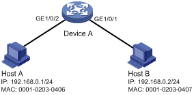
As shown in Figure 2, all hosts use static IP addresses.
Configure static IPv4SG bindings on Device A to meet the following requirements:
· All interfaces of Device A allow IP packets from Host A to pass.
· GigabitEthernet 1/0/1 of Device A allows IP packets from Host B to pass.
Configuration procedure
# Configure IP addresses for the interfaces. (Details not shown.)
# Enable IPv4SG on GigabitEthernet 1/0/2.
<DeviceA> system-view
[DeviceA] interface gigabitethernet 1/0/2
[DeviceA-GigabitEthernet1/0/2] ip verify source ip-address mac-address
[DeviceA-GigabitEthernet1/0/2] quit
# Configure a static IPv4SG binding for Host A.
[DeviceA] ip source binding ip-address 192.168.0.1 mac-address 0001-0203-0406
# Enable IPv4SG on GigabitEthernet 1/0/1.
[DeviceA] interface gigabitethernet 1/0/1
[DeviceA-GigabitEthernet1/0/1] ip verify source ip-address mac-address
# On GigabitEthernet 1/0/1, configure a static IPv4SG binding for Host B.
[DeviceA-GigabitEthernet1/0/1] ip source binding mac-address 0001-0203-0407
[DeviceA-GigabitEthernet1/0/1] quit
Verifying the configuration
# Verify that the static IPv4SG bindings are configured successfully on Device A.
<DeviceA> display ip source binding static
Total entries found: 2
IP Address MAC Address Interface VLAN Type
192.168.0.1 0001-0203-0406 N/A N/A Static
N/A 0001-0203-0407 GE1/0/1 N/A Static
Dynamic IPv4SG using DHCP snooping configuration example
Network requirements
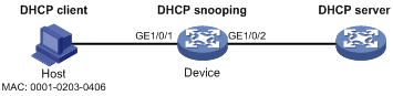
As shown in Figure 3, the host (the DHCP client) obtains an IP address from the DHCP server. Perform the following tasks:
· Enable DHCP snooping on the device to make sure the DHCP client obtains an IP address from the authorized DHCP server. To generate a DHCP snooping entry for the DHCP client, enable recording of client information in DHCP snooping entries.
· Enable dynamic IPv4SG on GigabitEthernet 1/0/1 to filter incoming packets by using the IPv4SG bindings generated based on DHCP snooping entries. Only packets from the DHCP client are allowed to pass.
Configuration procedure
1. Configure DHCP snooping:
# Configure IP addresses for the interfaces. (Details not shown.)
# Enable DHCP snooping.
<Device> system-view
[Device] dhcp snooping enable
# Configure GigabitEthernet 1/0/2 as a trusted interface.
[Device] interface gigabitethernet 1/0/2
[Device-GigabitEthernet1/0/2] dhcp snooping trust
[Device-GigabitEthernet1/0/2] quit
2. Configure IPv4SG on GigabitEthernet 1/0/1:
# Enable IPv4SG on GigabitEthernet 1/0/1 and verify the source IP address and MAC address for dynamic IPSG.
[Device] interface gigabitethernet 1/0/1
[Device-GigabitEthernet1/0/1] ip verify source ip-address mac-address
# Enable recording of client information in DHCP snooping entries on GigabitEthernet 1/0/1.
[Device-GigabitEthernet1/0/1] dhcp snooping binding record
[Device-GigabitEthernet1/0/1] quit
Verifying the configuration
# Display dynamic IPv4SG bindings generated based on DHCP snooping entries.
[Device] display ip source binding dhcp-snooping
Total entries found: 1
IP Address MAC Address Interface VLAN Type
192.168.0.1 0001-0203-0406 GE1/0/1 1 DHCP snooping
The output shows that GigabitEthernet 1/0/1 will filter packets based on the IPv4SG binding.
Dynamic IPv4SG using DHCP relay agent configuration example
Network requirements
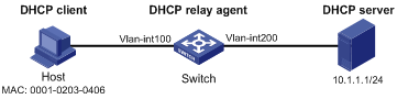
As shown in Figure 4, DHCP relay agent is enabled on the switch. The host obtains an IP address from the DHCP server through the DHCP relay agent.
Enable dynamic IPv4SG on VLAN-interface 100 to filter incoming packets by using the IPv4SG bindings generated based on DHCP relay entries.
Configuration procedure
1. Configure dynamic IPv4SG:
# Configure IP addresses for the interfaces. (Details not shown.)
# Enable IPv4SG on VLAN-interface 100 and verify the source IP address and MAC address for dynamic IPSG.
<Switch> system-view
[Switch] interface vlan-interface 100
[Switch-Vlan-interface100] ip verify source ip-address mac-address
[Switch-Vlan-interface100] quit
2. Configure the DHCP relay agent:
# Enable the DHCP service.
[Switch] dhcp enable
# Enable recording DHCP relay entries.
[Switch] dhcp relay client-information record
# Configure VLAN-interface 100 to operate in DHCP relay mode.
[Switch] interface vlan-interface 100
[Switch-Vlan-interface100] dhcp select relay
# Specify the IP address of the DHCP server.
[Switch-Vlan-interface100] dhcp relay server-address 10.1.1.1
[Switch-Vlan-interface100] quit
Verifying the configuration
# Display dynamic IPv4SG bindings generated based on DHCP relay entries.
[Switch] display ip source binding dhcp-relay
Total entries found: 1
IP Address MAC Address Interface VLAN Type
192.168.0.1 0001-0203-0406 Vlan100 100 DHCP relay
The output shows that VLAN-interface 100 will filter packets based on the IPv4SG binding.
Static IPv6SG configuration example
Network requirements
As shown in Figure 5, configure a static IPv6SG binding on GigabitEthernet 1/0/1 of the device to allow only IPv6 packets from the host to pass.
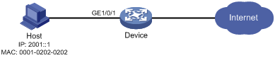
Configuration procedure
# Enable IPv6SG on GigabitEthernet 1/0/1.
<Device> system-view
[Device] interface gigabitethernet 1/0/1
[Device-GigabitEthernet1/0/1] ipv6 verify source ip-address mac-address
# On GigabitEthernet 1/0/1, configure a static IPv6SG binding for the host.
[Device-GigabitEthernet1/0/1] ipv6 source binding ip-address 2001::1 mac-address 0001-0202-0202
[Device-GigabitEthernet1/0/1] quit
Verifying the configuration
# Verify that the static IPv6SG binding is configured successfully on the device.
[Device] display ipv6 source binding static
Total entries found: 1
IPv6 Address MAC Address Interface VLAN Type
2001::1 0001-0202-0202 GE1/0/1 N/A Static
Dynamic IPv6SG using DHCPv6 snooping configuration example
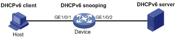
Network requirements
As shown in Figure 6, the host (the DHCPv6 client) obtains an IP address from the DHCPv6 server. Perform the following tasks:
· Enable DHCPv6 snooping on the device to make sure the DHCPv6 client obtains an IPv6 address from the authorized DHCPv6 server. To generate a DHCPv6 snooping entry for the DHCPv6 client, enable recording of client information in DHCPv6 snooping entries.
· Enable dynamic IPv6SG on GigabitEthernet 1/0/1 to filter incoming packets by using the IPv6SG bindings generated based on DHCPv6 snooping entries. Only packets from the DHCPv6 client are allowed to pass.
Configuration procedure
1. Configure DHCPv6 snooping:
# Enable DHCPv6 snooping globally.
<Device> system-view
[Device] ipv6 dhcp snooping enable
# Configure GigabitEthernet 1/0/2 as a trusted interface.
[Device] interface gigabitethernet 1/0/2
[Device-GigabitEthernet1/0/2] ipv6 dhcp snooping trust
[Device-GigabitEthernet1/0/2] quit
2. Enable IPv6SG:
# Enable IPv6SG on GigabitEthernet 1/0/1 and verify the source IP address and MAC address for dynamic IPv6SG.
[Device] interface gigabitethernet 1/0/1
[Device-GigabitEthernet1/0/1] ipv6 verify source ip-address mac-address
# Enable recording of client information in DHCPv6 snooping entries on GigabitEthernet 1/0/1.
[Device-GigabitEthernet1/0/1] ipv6 dhcp snooping binding record
[Device-GigabitEthernet1/0/1] quit
Verifying the configuration
# Display dynamic IPv6SG bindings generated based on DHCPv6 snooping entries.
[Device] display ipv6 source binding dhcpv6-snooping
Total entries found: 1
IPv6 Address MAC Address Interface VLAN Type
2001::1 040a-0000-0001 GE1/0/1 1 DHCPv6 snooping
The output shows that GigabitEthernet 1/0/1 will filter packets based on the IPv6SG binding.
Dynamic IPv6SG using DHCPv6 relay agent configuration example
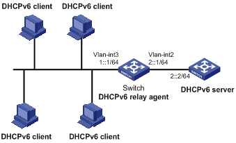
Network requirements
As shown in Figure 7, DHCPv6 relay agent is enabled on the switch. The clients obtain IPv6 addresses from the DHCPv6 server through the DHCPv6 relay agent.
Enable dynamic IPv6SG on VLAN-interface 3 to filter incoming packets by using the IPv6SG bindings generated based on DHCPv6 relay entries.
Configuration procedure
1. Configure the DHCPv6 relay agent:
# Create VLAN 2 and VLAN 3, assign interfaces to the VLANs, and specify IP addresses for VLAN-interface 2 and VLAN-interface 3. (Details not shown.)
# Enable the DHCPv6 relay agent on VLAN-interface 3.
[Switch] interface vlan-interface 3
[Switch-Vlan-interface3] ipv6 dhcp select relay
# Enable recording of DHCPv6 relay entries on the interface.
[Switch-Vlan-interface3] ipv6 dhcp relay client-information record
# Specify the DHCPv6 server address 2::2 on the relay agent.
[Switch-Vlan-interface3] ipv6 dhcp relay server-address 2::2
[Switch-Vlan-interface3] quit
2. Enable IPv6SG on VLAN-interface 3 and verify the source IP address and MAC address for dynamic IPv6SG.
<Switch> system-view
[Switch] interface vlan-interface 3
[Switch-Vlan-interface3] ipv6 verify source ip-address mac-address
[Switch-Vlan-interface3] quit
Verifying the configuration
# Display dynamic IPv6SG bindings generated based on DHCPv6 relay entries.
[Switch] display ipv6 source binding dhcpv6-relay
Total entries found: 1
IP Address MAC Address Interface VLAN Type
1::2 0001-0203-0406 Vlan3 3 DHCPv6 relay
The output shows that VLAN-interface 3 will filter packets based on the IPv6SG binding.