- Table of Contents
- Related Documents
-
| Title | Size | Download |
|---|---|---|
| 01-Text | 747.84 KB |
Overview
The PSR300-12A2 and PSR300-12D2 power supplies have the following features:
· Provide protection against input overcurrent, input undervoltage, output overvoltage, output short-circuit, and overtemperature.
· Support for 1+1 redundancy and load sharing.
· Hot swappable. You can hot swap a power supply when another power supply is operating.
Views
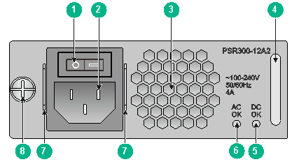
Figure 1 PSR300-12A2
|
(1) Power switch ("O" represents off and "—" represents on) |
|
|
(2) Power receptacle |
(3) Air vent |
|
(4) Handle |
(5) Power output status LED |
|
(6) Power input status LED |
(7) Securing holes for the power cord retaining clasp |
|
(8) Fastening screw |
|
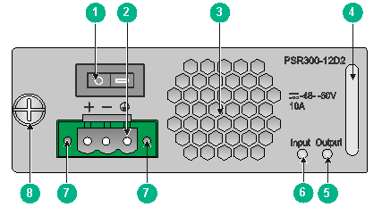
Figure 2 PSR300-12D2
|
(1) Power switch ("O" represents off and "—" represents on) |
|
|
(2) Power receptacle |
(3) Air vent |
|
(4) Handle |
(5) Power output status LED |
|
(6) Power input status LED |
(7) Screw holes for securing the power cord connector |
|
(8) Fastening screw |
|
Technical specifications
Table 1 Technical specifications
|
Item |
Specifications |
|
Rated input voltage |
· PSR300-12A2: 100 VAC to 240 VAC · PSR300-12D2: –48 VDC to –60 VDC |
|
Output voltage |
12 V |
|
Maximum output current |
25 A |
|
Maximum output power |
300 W |
|
Dimensions (H × W × D) |
40.13 × 101.6 × 234.9 mm (1.58 × 4.00 × 9.25 in) |
|
Operating temperature |
0°C to 55°C (32°F to 131°F) |
|
Operating humidity |
5% RH to 95% RH, noncondensing |
LEDs
Table 2 LED description
|
LED |
Status |
Description |
|
Power input status LED (AC OK or Input) |
Off |
No power is being input or an input failure has occurred. |
|
On |
Normal power input. |
|
|
Power output status LED (DC OK or Output) |
Off |
No power is being output or an output failure has occurred. |
|
On |
Normal power output. |
If the power input LED is on but the output LED is off, an output issue or an overtemperature condition might have occurred. To resolve the issue:
1. Turn off the power switch and disconnect the power cord. Then reconnect the power cord and turn on the power switch.
This operation resolves the power supply failure caused by an output overvoltage, output short-circuit, or output overcurrent condition. The power supply shuts down and latches off if one of these conditions occurs and cannot automatically restore operation.
2. If the issue persists, the temperature might be high. Take measures to decrease the temperature to an acceptable range. The power supply will automatically restore operation.
Installing and removing the power supply
Safety precautions
To avoid possible bodily injury and power supply and device damage, follow these safety precautions:
· When installing and removing the power supply, always wear an ESD wrist strap and make sure it makes good skin contact.
· Make sure the voltage of the power source is as required by the power supply, and the output voltage of the power supply is as required by the device.
· To avoid bodily injury, do not touch any bare wire or terminal.
· Do not place the power supply in a wet location, and prevent liquid from flowing into the power supply.
· To avoid power supply damage, do not open the power supply. If the internal wires or units are faulty, contact H3C Support.
Tools
When installing and removing a power supply and power cord, you must wear an ESD wrist strap. Prepare it yourself.
Installing and removing the power supply
The installation and removal procedures are similar for the PSR300-12A2 and PSR300-12D2 power supplies. The following procedures install and remove a PSR300-12D2 power supply.
Installing the power supply
|
|
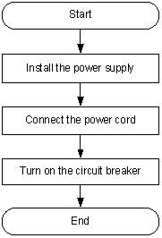
CAUTION: To avoid bodily injury and device damage, strictly follow the procedure in Figure 3 to install the power supply. |
Figure 3 Power supply installation procedure
To install the power supply:
1. Wear an ESD wrist strap and make sure the strap makes good skin contact and is reliably grounded.
2. Unpack the power supply and make sure the power supply model is as required.
Keep the power supply package secure for future use.
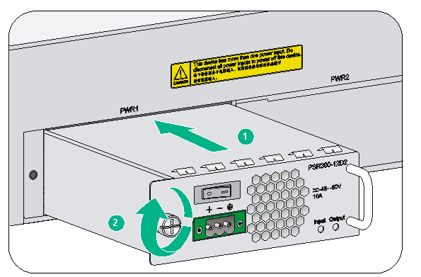
3. As shown in Figure 4, correctly orient the power supply (with the lettering on it upwards). Grasping the module handle with one hand and supporting the module bottom with the other, push the module slowly into the slot along the guide rails. Make sure the power supply has good contact with the backplane connectors.
The power supply and power supply slot are designed to prevent disorientation and misalignment. If you cannot insert the power supply smoothly into the slot, the orientation might be wrong or the power supply is not aligned correctly with the slot. Pull out the power supply, reorient the power supply or realign it with the slot, and insert it again.
4. When the power supply is fully seated in the slot, fasten the screw on the power supply.
Figure 4 Installing the power supply
Connecting the power cord
Connecting the AC power cord
|
|
WARNING! · Make sure each power cord has a separate circuit breaker. · Before connecting a power cord, turn off the circuit breaker for it. |
To connect the AC power cord:
1. As shown in Figure 5, pivot up the power cord retaining clip, insert the female connector of the AC power cord into the AC-input power receptacle on the power supply, and then pivot down the power cord retaining clip.
Figure 5 Connecting the AC power cord to the power supply
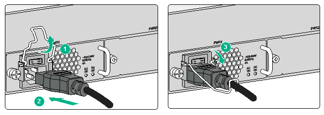
2. Connect the other end of the AC power cord into an AC power source, and turn on the circuit breaker for the power cord.
3. Turn on the power switch. If the AC OK LED is on, the power cord is connected correctly. If the AC OK LED is off, the connection might be wrong. Verify the installation and resolve the issue.
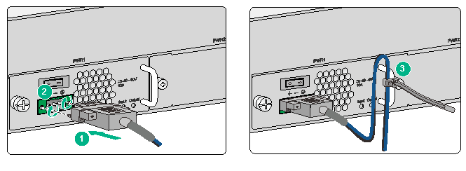
Connecting the DC power cord
1. As shown in Figure 6, insert the connector of the DC power cord into the DC-input receptacle on the power supply. Then fasten the screws on the connector.
The connector of the DC power cord and the DC-input receptacle are designed to prevent disorientation. If you cannot insert the connector smoothly into the receptacle, the orientation might be wrong. Remove the connector, reorient it, and connect it again.
2. Use a releasable cable tie to secure the power cord to the handle of the power supply.
Figure 6 Connecting the DC power cord
3. Connect the other end of the DC power cord to a DC power source.
4. Turn on the power switch on the power supply. If the Input LED is on, the power cord is connected correctly. If the Input LED is off, the connection might be wrong. Verify the installation and resolve the issue.
Removing the power supply
|
|
CAUTION: To avoid bodily injury and device damage, strictly follow the procedure in Figure 7 to remove the power supply. |
Figure 7 Power supply removal procedure
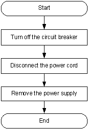
To remove the power supply:
1. Turn off the circuit breaker for the power cord.
2. Wear an ESD wrist strap and make sure the strap makes good skin contact and is reliably grounded.
4. Loosen the releasable cable tie that secures the power cord to the handle of the power supply.
5. Loosen the screws on the power cord connector and then remove the power cord.
Figure 8 Removing a DC power cord connector
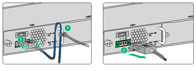
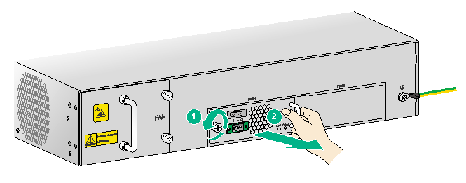
|
(1) Loosen the screws on the power cord connector |
|
(2) Pull the connector out |
6. As shown in Figure 9, loosen the screw on the power supply. Grasping the power supply handle with one hand, pull the power supply part way out of the slot. Supporting the power supply bottom with the other, pull the power supply slowly out of the slot along the guide rails.
Figure 9 Removing the power supply
7. Put the removed power supply on an antistatic mat or into its package.
8. If you are not to install a new power supply, install the filler panel in the slot to prevent dust from entering the chassis.
