- Table of Contents
- Related Documents
-
01-Text
Download Book (1.44 MB)Contents
Installing and removing a transceiver module
Installing and removing a bail latch transceiver module
Installing and removing a pull latch transceiver module
Installing and removing a transceiver module with captive screws
Installing and removing a network cable
Overview
A transceiver module converts electrical data signals to laser light, which is then transmitted over an optical fiber. It can transmit optical signals over long distance with low signal loss. H3C devices support many types of transceiver modules in different specifications.
H3C fiber network cables are Active Optical Cables (AOCs) terminated with transceiver modules. H3C copper network cables include Active Copper Cables (ACCs) and Direct Attach Cables (DACs), which are coaxial cables terminated with transceiver modules. Fiber and copper network cables are collectively referred to as "network cable" in this document.
H3C devices support the following transceiver modules and network cables:
· Transceiver modules—QSFP-DD, QSFP28, CFP, CFP2, CXP, QSFP+, SFP28, SFP+, XFP, and SFP transceiver modules.
· Fiber network cables—QSFP-DD, QSFP28, CXP, QSFP+, SFP28, and SFP+ fiber network cables.
· Copper network cables—QSFP-DD, QSFP28, QSFP28 to SFP28, QSFP+, QSFP+ to SFP+, SFP28, SFP+, CX4, and GE SFP copper network cables.
|
|
NOTE: · The available transceiver modules and network cables vary by device model. For transceiver modules and network cables available for an H3C device, see the installation guide for the product. · H3C transceiver modules and network cables are subject to change over time. For the most recent list of H3C transceiver modules and network cables, contact H3C Support or marketing staff |
Preparing for installation
|
|
CAUTION: · To avoid ESD damage to transceiver modules, network cables, or electronic components on the device, always wear an ESD wrist strap while handling transceiver module or network cables. In addition, make sure anti-ESD measures (such as dust prevention and temperature and humidity maintenance) are in place at the installation site. · If ESD gloves are available, wear the gloves first and then the ESD wrist strap and make sure the strap makes good contact with the glove. |
To attach an ESD wrist strap:
1. Wear the strap on your wrist and fasten it securely. Make sure the strap makes good skin contact.
2. Ground the strap reliably.
¡ If the device has an ESD jack, connect the grounding terminal of the strap to the ESD jack, as shown in Figure 1.
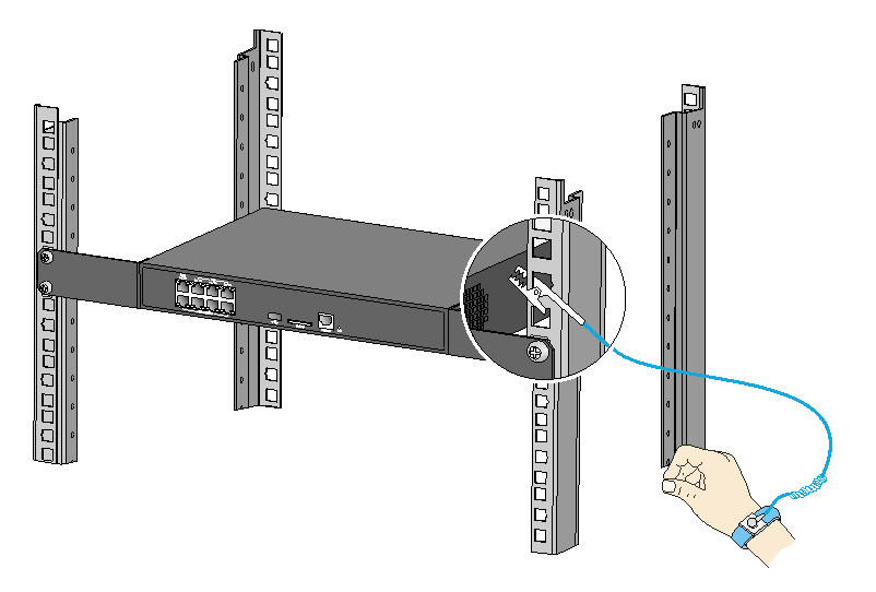
¡ If the device does not have an ESD jack, clip the grounding terminal of the strap to a rack post as shown in Figure 2, or take other measures to ground the strap reliably.
Figure 1 Attaching an ESD wrist strap (1)
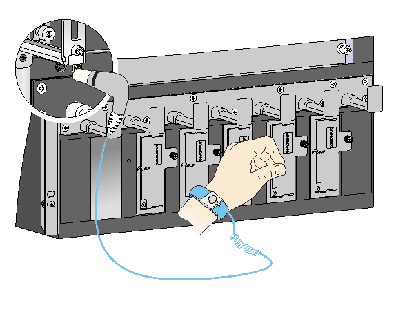
Figure 2 Attaching an ESD wrist strap (2)
Installing and removing a transceiver module
|
|
WARNING! Do not stare into any open apertures of operating transceiver modules or optical fiber connectors. The laser light emitted from these apertures might hurt your eyes. |
|
|
CAUTION: · During the installation or removal process, be careful not to touch the golden plating on the transceiver module. · Before inserting a transceiver module into a port, make sure the transceiver module aligns with the port correctly. |
H3C transceiver modules are available in three types:
· Bale-clasp latch transceiver modules—Include CFP2, QSFP+, SFP28, SFP+, XFP, and SFP transceiver modules. For the installation and removal procedure, see "Installing and removing a bail latch transceiver module."
· Pull latch transceiver modules—Include QSFP-DD, QSFP28, CXP, and QSFP+ transceiver modules. For the installation and removal procedure, see "Installing and removing a pull latch transceiver module."
· Transceiver modules with captive screws—Include CFP transceiver modules. For the installation and removal procedure, see "Installing and removing a transceiver module with captive screws."
Installing and removing a bail latch transceiver module
This installation method is applicable to the CFP2, QSFP+, SFP28, SFP+, XFP, and SFP transceiver modules. The following procedure uses a QSFP+ transceiver module as an example.
Installation procedure
1. Remove the dust plug from the target fiber port.
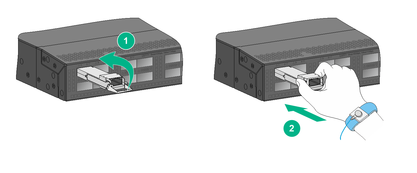
2. As shown by callout 1 in Figure 3, close the bail latch upward to catch the knob on the top of the transceiver module.
3. Grasp the transceiver module between your thumb and index finger and correctly orient it. Align it with the fiber port and push it gently into the port until you feel it snaps into place. See callout 2 in Figure 3.
Transceiver modules and fiber ports have disorientation rejection designs. If you cannot insert a transceiver module easily into a port, the orientation might be wrong. Remove and reorient the transceiver module.
In case of limited space, you can gently push against the front face of the transceiver module instead of the two sides.
Figure 3 Installing a bail latch transceiver module (QSFP+)
4. Grasping the fiber connector between your thumb and index finger, align it with the transceiver module optical bore and push it into the bore.
Transceiver module optical bores and fiber connectors have disorientation rejection designs. If you cannot insert a fiber connector easily into a transceiver module optical bore, the orientation might be wrong. Remove and reorient the connector.
5. If you are not to install an optical fiber, insert a dust plug into the transceiver module bore.
|
|
NOTE: The triangular pin on a transceiver module and the hole in a fiber port function together to prevent the module from disengaging from the port. |
Removal procedure
1. Remove the optical fiber from the transceiver module.
There is a latching mechanism between a fiber connector and transceiver module port to prevent connector disengagement. Release the latching mechanism before removing the optical fiber. To avoid damages, do not use excessive force.
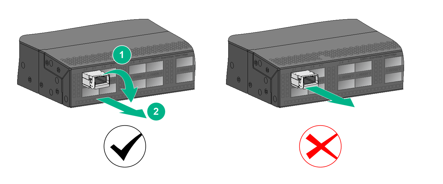
2. Pivot the bail latch down until it stops, as shown by callout 1 in Figure 4.
3. Holding the bail latch, carefully pull the transceiver module straight out of the fiber port.
If you use force at an angle as shown in Figure 6, you can hardly pull the transceiver module out and the transceiver module or fiber port might be damaged. If you forcibly pull out of the transceiver module without pivoting the bail latch down, the triangular pin of the transceiver module and the fiber port might be damaged.
To avoid damaging the bail latch, use event force to pull the transceiver module out.
Figure 4 Correct and wrong removal practices (QSFP+ transceiver module)
4. Insert the dust plug into the fiber port.
Installing and removing a pull latch transceiver module
This installation procedure is applicable to QSFP-DD, QSFP28, CXP, and QSFP+ transceiver modules.
The pull latch of transceiver modules can be plastic or rubber. The installation procedure is similar. The following procedure uses a rubber pull latch as an example.
Installation procedure
1. Remove the dust plug from the target fiber port.
2. As shown in Figure 5, correctly orient the transceiver module and align it with the fiber port. Push it gently into the port until you feel it snap into place.
Transceiver modules and fiber ports have disorientation rejection designs. If you cannot insert a transceiver module easily into a port, the orientation might be wrong. Remove and reorient the transceiver module.
In case of limited space, you can gently push against the front face of the transceiver module instead of the two sides.
Figure 5 Installing a CXP transceiver module
3. Grasping the fiber connector between your thumb and index finger, align it with the transceiver module optical bore and push it into the optical bore.
Transceiver module optical bores and fiber connectors have disorientation rejection designs. If you cannot insert a fiber connector easily into a transceiver module bore, the orientation might be wrong. Remove and reorient the connector.
4. If you are not to install an optical fiber, insert a dust plug into the transceiver module bore.
|
|
NOTE: The triangular pin on a transceiver module and the hole in a fiber port function together to prevent the module from disengaging from the port. |
Removal procedure
1. Remove the optical fiber from the transceiver module.
There is a latching mechanism between a fiber connector and transceiver module. Release the latching before removing the optical fiber. To avoid damages, do not use excessive force.
2. Putting your forefinger into the pull ring, carefully pull the transceiver module straight out of the fiber port.
As shown in Figure 6, if you use force at an angle, you can hardly pull the transceiver module out and the transceiver module or fiber port might be damaged.
To avoid damaging the pull latch, use event force to pull the transceiver module out.
Figure 6 Correct and wrong removal practices (CXP transceiver module)
3. Insert the dust plug into the fiber port.
Installing and removing a transceiver module with captive screws
This installation procedure is applicable only to a CFP transceiver module.
Installation procedure
1. Remove the dust plug from the target fiber port.
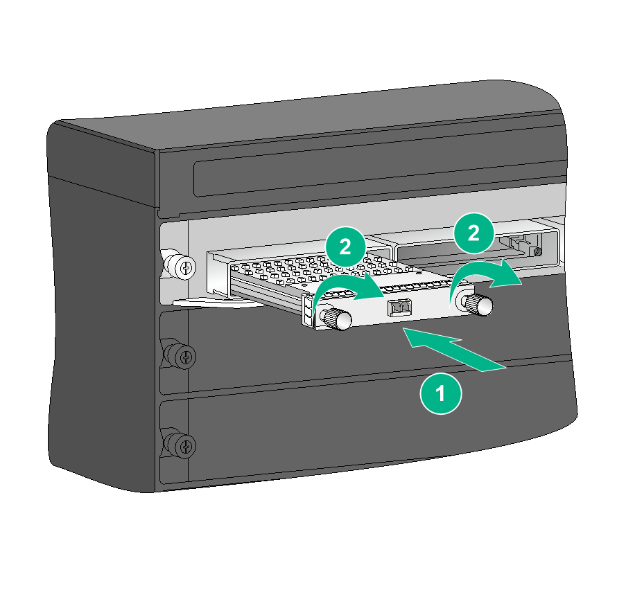
2. As shown in Figure 3, correctly orient the transceiver module and align it with the fiber port. Push it gently into the port until you feel it snaps into place.
Transceiver modules and fiber ports have disorientation rejection designs. If you cannot insert a transceiver module easily into a port, the orientation might be wrong. Remove and reorient the transceiver module.
In case of limited space, you can gently push against the front face of the transceiver module instead of the two sides.
3. Fasten the captive screws on the transceiver module to secure it in place.
Figure 7 Installing a CFP transceiver module
4. Grasping the fiber connector between your thumb and index finger, align it with the transceiver module optical bores and push it into the bores.
Transceiver module optical bores and fiber connectors have disorientation rejection designs. If you cannot insert a fiber connector easily into a transceiver module bores, the orientation might be wrong. Remove and reorient the connector.
5. If you are not to install optical fibers, insert dust plugs into the transceiver module bores.
Removal procedure
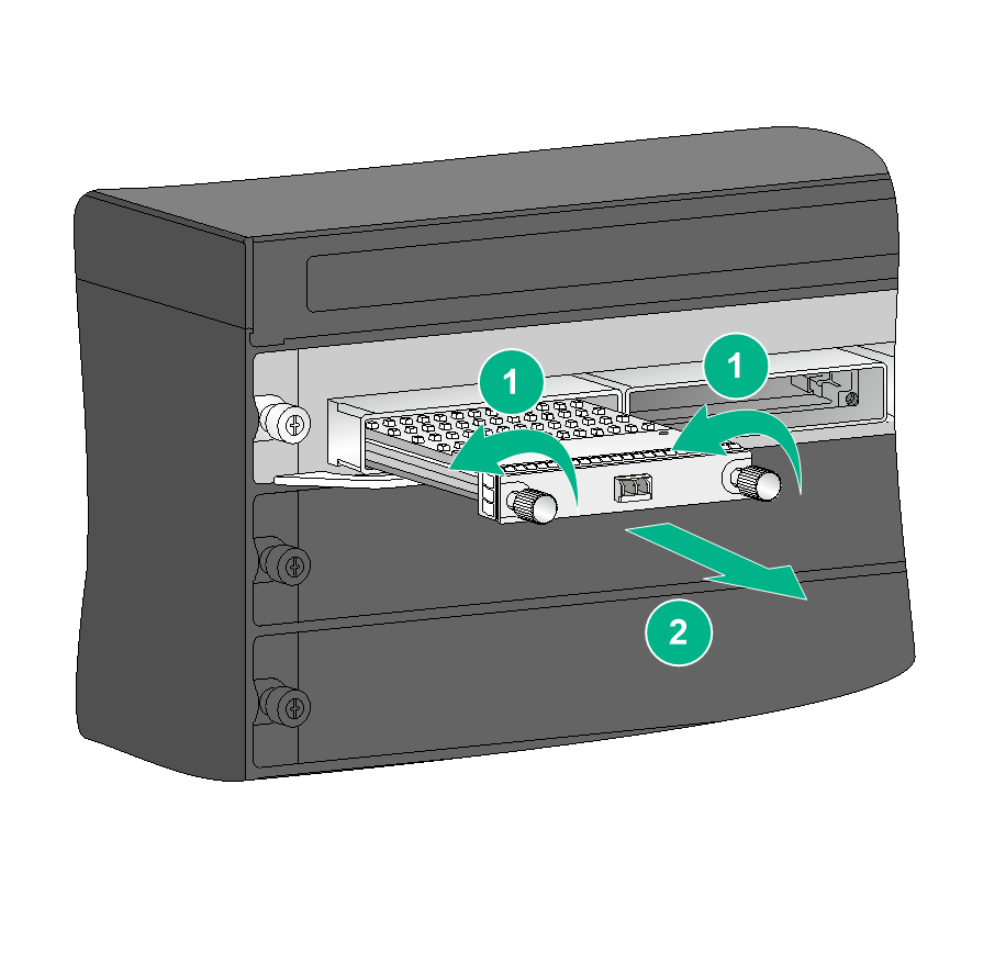
1. Remove the optical fiber from the transceiver module.
There is a latching mechanism between a fiber connector and transceiver module port to prevent connector disengagement. Release the latching before removing the optical fiber. To avoid damages, do not use excessive force.
2. Loosen the captive screws on the transceiver module.
3. Carefully pull the transceiver module straight out of the fiber port.
If you use force at an angle, you can hardly pull the transceiver module out and the transceiver module or fiber port might be damaged.
Figure 8 Removing a CFP transceiver module
4. Insert the dust plug into the fiber port.
Installing and removing a network cable
|
|
CAUTION: · Make sure the two modular ends of a network cable are compatible with the ports into which they will be inserted. · Do not touch the golden plating on the two modular ends of the network cable during the installation or removal process. · To avoid network cable damage and signal loss, do not strain or tangle a network cable. · Before inserting a modular end of a network cable into a port, make sure the module aligns with the port correctly. |
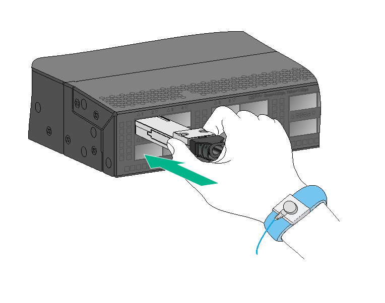
A QSFP+ to 4 × SFP+ network cable has a 40G QSFP+ module at one end and four SFP+ transceiver modules at the other end. A QSFP28 to 4 × SFP28 network cable has a 100G QSFP28 module at one end and four 25G SFP28 transceiver modules at the other end.
The installation and removal procedure is the same for H3C network cables. The following procedure uses a QSFP+ network cable as an example.
Installation procedure
1. Remove the dust plug from the target fiber port.
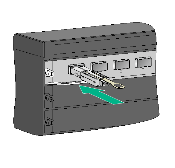
2. As shown in Figure 3, correctly orient the modular end of the network cable. Align the module with the fiber port and push it gently into the port until you feel it snaps into place.
Transceiver modules and fiber ports have disorientation rejection structures. If you cannot insert a transceiver module easily into a port, remove and reorient the transceiver module.
Figure 9 Installing a network cable (QSFP+)
Removal procedure
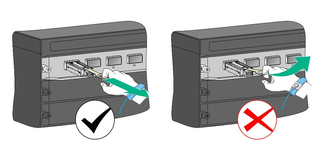
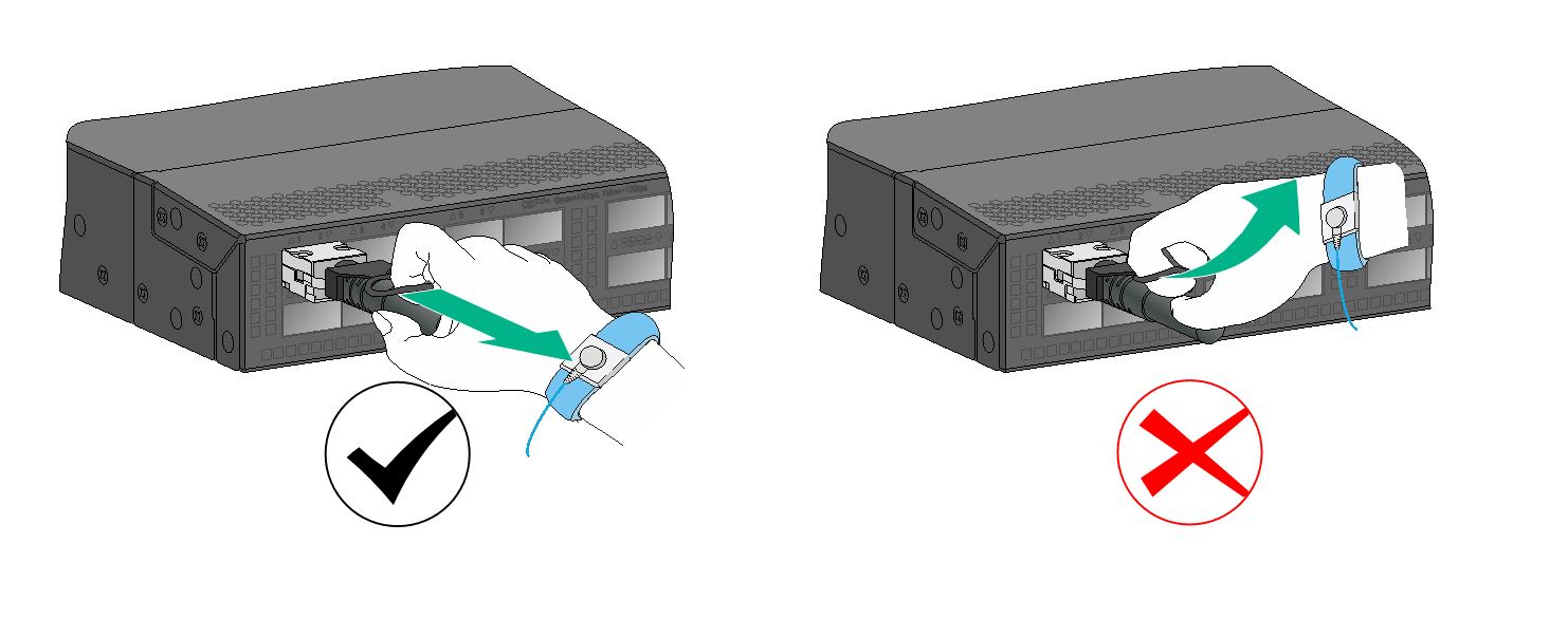
1. Putting your forefinger into the pull latch, carefully pull the network cable straight out of the fiber port.
As shown in Figure 10, if you use force at an angle, you can hardly pull the network cable out and the network cable or fiber port might be damaged.
Figure 10 Correct and wrong removal practices (QSFP+ network cable)
2. Insert the dust plug into the fiber port.
Verifying the installation
After a transceiver module or network cable is installed, execute the display transceiver interface command on the device to verify the installation.
· If the command displays information about the transceiver module or network cable correctly, the installation is correct.
The command output depends on the transceiver module or network cable type, device model, and software version. The following sample output displays information about a QSFP28 network cable installed on HundredGigE 1/0/10:
<Sysname> display transceiver interface hundredgige 1/0/10
HundredGigE1/0/10 transceiver information:
Transceiver Type : STACK_QSFP28
Connector Type : COPPER
Wavelength(nm) : N/A
Transfer Distance(m) : 5
Digital Diagnostic Monitoring : NO
Vendor Name : H3C
· If an error message is displayed, follow the procedures described in this document to remove and reinstall the transceiver module or network cable. If the issue persists, contact H3C Support.
The following are error messages that might be displayed.
¡ The port is not a fiber port.
Error: The port has no transceiver information.
¡ No transceiver module or network cable is present in the port.
Error: The transceiver is absent.
¡ Failed to obtain information about the transceiver module or network cable.
Error: Reading information from the transceiver failed.
