- Table of Contents
- Related Documents
-
| Title | Size | Download |
|---|---|---|
| 01-Text | 4.21 MB |
Contents
Installing SNA Center and its components
Deployment procedure at a glance
Installing the H3Linux operating system and SNA Installer platform on a server
Configuring cluster parameters
Configuring nodes and deploying a cluster
Obtaining the device information file
Registering a license for the first time
Registering an upgrade license
Managing SNA Center components
Backing up and restoring SNA Center configuration
Scaling out SNA Center and its components
Scaling out SNA Center in standalone mode
Scaling out SNA Center in cluster mode
(Optional) Removing a scaled-out instance·
Upgrading the SNA Installer platform
Executing the pre-upgrade script
Upgrading the H3Linux OS and SNA Installer
Failed to upgrade SNA Installer to V500R001B05D001 or later from an earlier version
Appendix B SNA Center software dependencies
Introduction
This document describes the procedure for deploying SNA Center and its components.
H3C SeerNetwork Architecture (SNA) Center is the core component of the next-generation smart network SNA to provide unified network management, control, analysis, and service orchestration. SNA Center is able to coordinate services in different management zones to simplify operations and reduce operation costs. It detects network conditions in real time and allows intent-based or network condition-based analysis to bring automated service deployment and risk prediction. This makes networks more simple, intelligent, and effective.
Preparing for installation
Deployment mode
SNA Center is deployed on SNA Installer and supports deployment in standalone mode or three-host cluster node. In standalone mode, it offers all its functions on a single master node. In cluster mode, it offers its functions on a cluster of three master nodes. You can add worker nodes to the cluster for service expansion.
|
|
IMPORTANT: · To ensure high service availability, deploy SNA Center in three-host cluster mode as a best practice. · If you must deploy SNA Center in standalone mode, back up the system and configuration data to a backup physical server regularly and disable services that require constant presence of SNA Center controllers. An SNA Center that has been deployed in standalone mode can be smoothly expanded to three-host master mode. |
|
|
NOTE: The standalone deployment mode, with all components of SNA Center deployed on a single server, cannot guarantee service continuity. During version upgrade or in case of hardware failure, SNA services are not available and the real-time services associated with SNA Center are interrupted. In addition, hardware failure of the server might result in data loss and configuration restoration failure. |
Hardware requirements
The hardware requirements are the same for deploying SNA Center in standalone mode or cluster mode.
Physical servers
The server hardware requirements depend on SNA Center deployment scheme. Table 1 describes the hardware requirements for deploying only controllers in SNA Center. Table 2 describes the hardware requirements for deploying controllers and the SeerAnalyzer in SNA Center. The minimum configuration supports only essential functions, and is inadequate for actual service deployment. The recommended configuration supports all functions.
Table 1 Hardware requirements for deploying only controllers in SNA Center
|
Item |
Minimum configuration |
Recommended configuration |
|
CPU |
x86-64 (Intel 64/AMD 64) 16 cores 2.0 GHz or above |
x86-64 (Intel 64/AMD 64) 16 cores 2.0 GHz or above |
|
Memory size |
64 GB or above |
64 GB or above |
|
Drive |
· One of the drive configuration options: ¡ 500 GB or above of an SAS SSD or NVMe SSD ¡ Two 500 GB or above of 7.2K RPM SATA/SAS HDDs · One RAID controller ¡ 1G cache memory ¡ RAID 1, 5, or 10 setup with the drive space no less than 500 GB |
· One of the drive configuration options: ¡ 1 TB or above of SAS SSD or NVMe SSD ¡ Two 1 TB or above of 7.2K RPM SATA/SAS HDDs · One RAID controller ¡ 1G cache memory ¡ RAID 1, 5, or 10 setup with the drive space no less than 1 TB |
|
NIC |
1 × 1 Gbps or above Ethernet port |
Non-redundancy mode: · Campus/WAN: 1 × 1 Gbps or above Ethernet port · DC: 1 × 10Gbps or above Ethernet port Redundancy mode: · Campus/WAN: 2 × 1 Gbps Linux bonding interfaces · DC: 2 × 10 Gbps Linux bonding interfaces |
Table 2 Hardware requirements for deploying controllers and the SeerAnalyzer in SNA Center
|
Item |
Minimum configuration |
Recommended configuration |
|
CPU |
x86-64 (Intel 64/AMD 64) 16 cores 2.0 GHz or above |
x86-64 (Intel 64/AMD 64) 16 cores 2.0 GHz or above |
|
Memory size |
256 GB or above |
256 GB or above |
|
Drive |
· One of the drive configuration options: ¡ 1 TB or above of SAS SSD or NVMe SSD ¡ Two 1 TB or above of 7.2K RPM SATA/SAS HDDs · One RAID controller ¡ 1G cache memory ¡ RAID 1, 5, or 10 setup with the drive space no less than 1 TB |
· One of the drive configuration options: ¡ 2 TB or above of SAS SSD or NVMe SSD ¡ Two 2 TB or above of 7.2K RPM SATA/SAS HDDs · One RAID controller ¡ 1G cache memory ¡ RAID 1, 5, or 10 setup with the drive space no less than 2 TB |
|
NIC |
2 × 1 Gbps or above Ethernet ports |
Non-redundancy mode: · Campus/WAN: 1 × 1 Gbps or above and 1 × 10 Gbps or above Ethernet ports · DC: 2 × 10 Gbps or above Ethernet ports Redundancy mode: · Campus/WAN: 2 × 1 Gbps Linux bonding interfaces and 2 × 10 Gbps Linux bonding interfaces · DC: 4 × 10 Gbps Linux bonding interfaces |
VMs
SNA Center supports only three-host cluster deployment on VMs, with each VM as a master node. You can deploy SNA Center with only a single controller (VCFC-Campus or VCFC-WAN controller only) on VMs.
Only the following virtualization platforms support SNA Center deployment:
· VMware ESXi 6.0.0
· H3C_CAS-E0526 or H3C CAS-E0530.
Table 3 VM configuration requirements for SNA Center deployment
|
CPU |
Memory |
Hard drive |
Virtual drive |
NIC |
|
16 or more vCPUs |
64 GB or above |
· 7.2K RPM SATA/SAS HDDs with HA configuration · RAID controller with 1 GB cache memory |
Two virtual drives, with each virtual drive corresponding to a drive on a physical server. Drive size with HA configured: · Drive 1: 1 GB or above, installed with etcd (path: /var/lib/etcd) · Drive 2: 1 TB or above, installed with other parts of the system |
1 × 1 Gbps or above port |
|
|
IMPORTANT: · Each vCPU assigned to SNA Center must have an exclusive use of a physical CPU core. · The memory and drive size must meet the preceding requirements. · To ensure SNA Center stability, virtual resource overcommitment is not allowed. · Do not install SNA Center-deployed VMs and other VMs on the same physical server. |
Software requirements
|
Device |
Requirements |
|
Server |
Operating system: Support for CentOS 7.5 or higher versions |
|
Client |
Browser for login: Google Chrome 60 or higher |
|
|
NOTE: Software on which SNA Center depends will be installed automatically during SNA Center installation and no extra operations are required. For more information about the software dependencies, see "Appendix B SNA Center software dependencies." |
Pre-installation checklist
Table 4 Pre-installation checklist
|
Item |
Requirements |
Result |
|
|
Server |
Hardware |
The CPU, memory, disk, and NIC settings are as required. |
|
|
Software |
· The server supports operating system CentOS 7.5 or its higher versions. · The system time settings are configured correctly. As a best practice, configure NTP on each node and specify the same time source for all the nodes. |
|
|
|
Client |
Google Chrome 60 or a higher version is installed on the client. |
|
|
Installing SNA Center and its components
|
|
IMPORTANT: · As a best practice, set the server's next startup mode to UEFI. · When using HDM to install the operating system for H3C servers, do not use KVM to install the same image simultaneously for multiple servers. · A power failure during the installation might cause installation failure of some service components. For function integrity, perform a reinstallation if a power failure has occurred during the installation process. · During the SNA Center deployment process, do not enable or disable firewall services. |
Deployment procedure at a glance
1. Prepare for installation.
To deploy SNA Center in standalone mode, prepare one physical server. To deploy SNA Center in three-host cluster mode, prepare three physical servers.
2. Deploy the H3Linux operating system and SNA Installer platform.
3. Deploy SNA Center.
In standalone node, deploy SNA Center on the master node. In cluster mode, deploy SNA Center on the three master nodes.
4. Deploy SNA Center components.
In standalone node, you can only deploy campus network components.
|
|
NOTE: Support for deployment and scale-out varies by component. |
Obtaining the system image
Obtain the SNA_CENTER-PACKAGE-version.iso system image file. version represents the software version number. The image file contains the installation packages of the operating system, SNA Installer, and SNA Center.
Installing the H3Linux operating system and SNA Installer platform on a server
|
|
IMPORTANT: Installing the H3Linux operating system on a server that already has an operating system installed replaces the existing operating system. To avoid data loss, back up data before you install the H3Linux operating system. |
The following procedure installs the H3Linux operating system on a server without an operating system installed. SNA Installer is automatically installed during the operating system installation process.
To install the H3Linux operating system and SNA Installer platform:
1. Use the remote console on the server to load the ISO image through the virtual optical drive.
2. Configure the server to boot from the virtual optical drive and then restart the server.
The INSTALLATION SUMMARY page opens.
Figure 1 INSTALLATION SUMMARY page
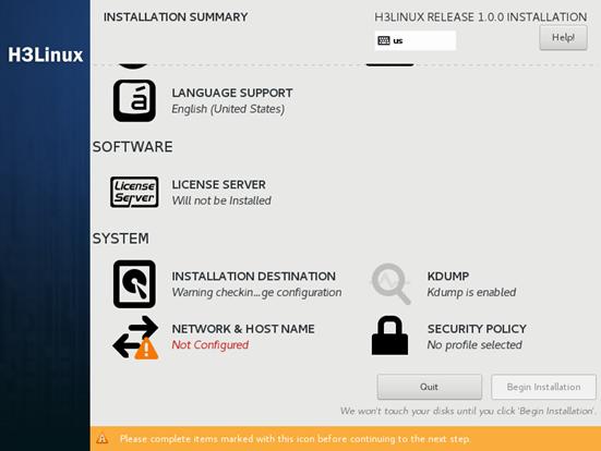
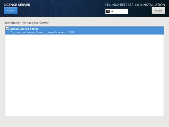
3. (Optional.) In the SOFTWARE area, click LICENSE SERVER, and then select Install License Server to install the license server.
|
|
IMPORTANT: Deploying the license server in a virtualization environment incurs security risks. As a best practice, do install the license server together with SNA Center in a virtualization environment. |
|
|
NOTE: · You can install the license server on two or three nodes in the SNA Installer cluster for HA or on only one server that is in or out of the cluster. As a best practice, install the license server on all the three master nodes. For more information about license server HA, see H3C License Server Installation Guide. · If you install the license server on a server that is not in the cluster, make sure the server can communicate with all the three master nodes in the cluster. |
Figure 2 LICENSE SERVER page
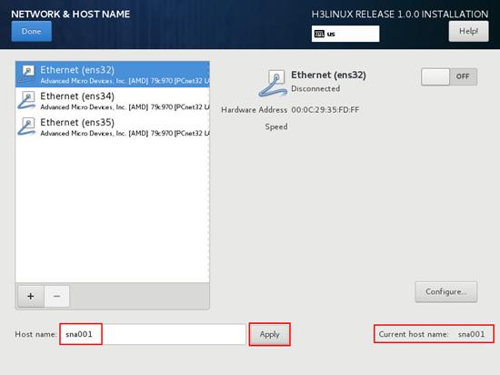
4. In the SYSTEM area, click NETWORK & HOST NAME. On the NETWORK & HOST NAME page, perform the following tasks:
a. Enter a new host name in the Host name field and then click Apply.
|
|
IMPORTANT: · To avoid cluster creation failure, configure different host names for the nodes in a cluster. A host name must be a string of up to 63 characters. It can contain only lower-case letters, digits, hyphens (-), and dots (.) but cannot start or end with a hyphen (-) or dot (.). · You cannot change the host name after the installation. If you must change it, contact the after-sales engineer. |
b. Click Configure to enter the network configuration page.
|
|
IMPORTANT: Configure network settings for only one NIC and disable the other NICs. |
Figure 3 NETWORK & HOST NAME page
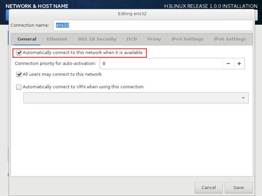
5. Configure the network settings as follows:
a. Click the General tab, select Automatically connect to this network when it is available, and retain the default setting for the All users may connect to this network field.
Figure 4 General settings
b. Click the IPv4 Settings tab, select Manual from the Method field, and then click Add to add an IPv4 address for the server. You must specify a gateway for the server when adding an IPv4 address.
|
|
CAUTION: · The 172.17.0.0/16 network segment is used by Docker and Harbor. To avoid unavailability of SNA Installer cluster, do not add an IPv4 address in either network segment. · To avoid service failure, do not use the ifconfig command to modify the NIC settings of the nodes. |
Figure 5 Configuring an IPv4 address for the server
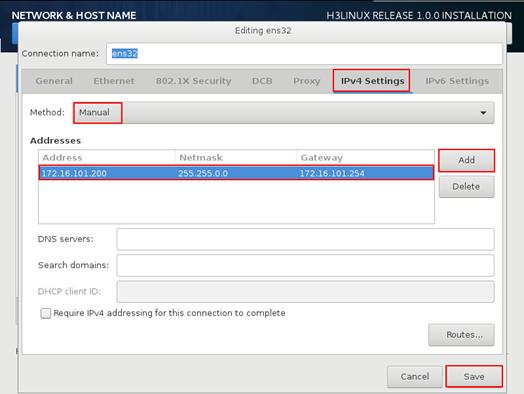
c. Click Save to save the configuration.
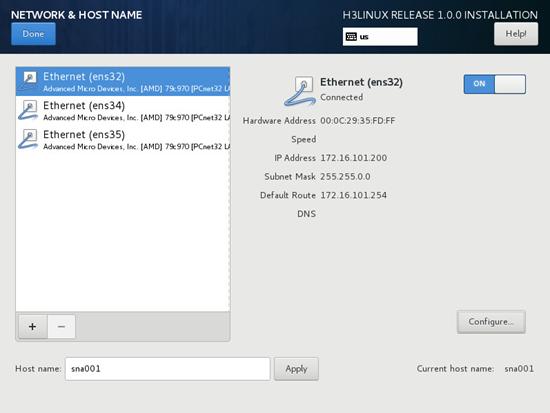
6. On the NETWORK & HOST NAME page, verify that the NIC settings are correct and the NICs are in correct state. Then, click Done to return to the INSTALLATION SUMMARY page.
Figure 6 NETWORK & HOST NAME page
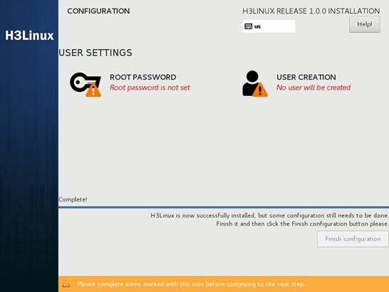
7. Click Begin Installation to start the installation. During the installation process, you will be prompted to configure USER SETTINGS as shown in Figure 7. You can set the root password for the system at the prompt or set the password after the installation as shown in Figure 8.
Figure 7 Setting the root password
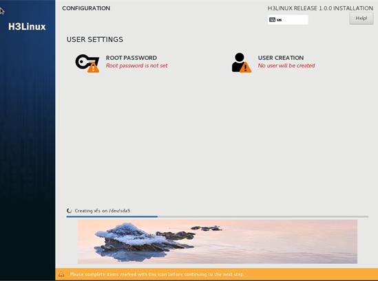
Figure 8 Setting the root password
|
|
IMPORTANT: Before the system restarts, terminate the connection to the virtual optical drive used for ISO image loading. |
After the installation is complete, the system reboots to finish the installation of the operating system. If you set the root password after the installation, click Finish configuration for the system to restart.
The H3Linux login page opens after the system restarts.
Figure 9 H3Linux login page
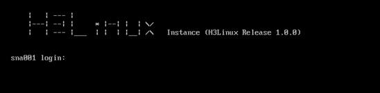
8. Use the root password to access the H3Linux operating system and execute the systemctl status matrix command to view the installation result. The installation succeeds if the active state is active (running).
[root@sna001 ~]# systemctl status matrix
matrix.service - Matrix Server
Loaded: loaded (/usr/lib/systemd/system/matrix.service; enabled; vendor preset: disabled)
Active: active (running) since Thu 2019-04-11 00:44:51 CST; 18h ago
Main PID: 1180 (karaf)
...
Installing SNA Center
Logging in to SNA Installer
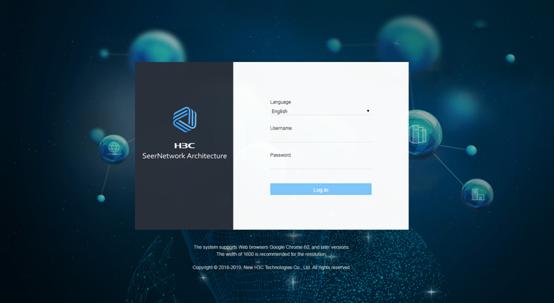
1. Enter https://sna_Installer_ip_address:8443/matrix/ui in the address bar and then press Enter. sna_Installer_ip_address represents the IP address of the server on which SNA Installer is installed. 8443 represents the default port number.
Figure 10 SNA Installer platform login page
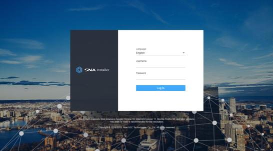
2. Select a language, enter the username and password, and then click Log in.
The default username is admin and the default password is admin@h3c.
Configuring cluster parameters
The system opens the deployment wizard at the first login. On the Configure cluster parameters page, configure cluster parameters as shown in Table 5 and then click Apply. After the system displays a message that the cluster parameters are configured or modified successfully, click Next.
Figure 11 Configuring cluster parameters
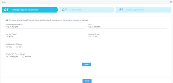
Table 5 Cluster parameters description
|
Item |
Description |
|
Cluster internal virtual IP |
Enter the IP address for internal communication. The mask length is set to 32 and the IP address cannot be modified once configured. This address must be in the same network segment as the master nodes. |
|
VIP |
Enter the IP address for northbound interface services. The mask length is set to 32. This address must be in the same network segment as the master nodes. |
|
Service IP pool |
Specify an address pool for IP assignment to services in the cluster. This address cannot conflict with other network segments in the deployment environment. |
|
Container IP pool |
Specify an address pool for IP assignment to containers. This address cannot conflict with other network segments in the deployment environment. |
|
Use internal NTP server |
Select whether to use the internal NTP server. If you select No, you must specify an NTP server. |
|
NTP server IP |
Enter the IP address of an NTP server. The IP address cannot be the same as the IP address of any node in the cluster. |
|
Deploy NFS shared storage |
Select whether to deploy NFS shared storage. If you select External, you must specify an external storage path. In this configuration, select Undeployed. |
|
External storage path |
Specify the external storage path for the NFS server. |
Configuring nodes and deploying a cluster
For standalone deployment, add one master node on SNA Installer. For cluster deployment, add three master nodes on SNA Installer and deploy the cluster.
To configure nodes and deploy a cluster:
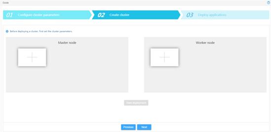
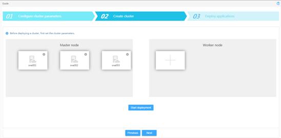
1. In the Master node area, click the plus icon.
Figure 12 Creating a cluster
2. Configure node parameters as shown in Table 6 and then click Apply.
Figure 13 Configuring node parameters
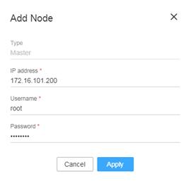
Table 6 Node parameter description
|
Item |
Description |
|
Type |
Displays the node type. Options include Master and Worker. This field cannot be modified. |
|
IP address |
Specify the IP address of the node. |
|
Username |
Specify the username for the root user to access the operating system. |
|
Password |
Specify the password for the root user to access the operating system. |
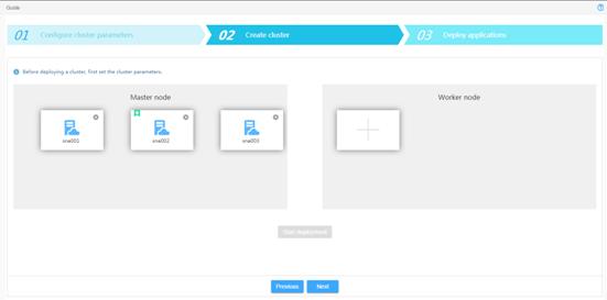
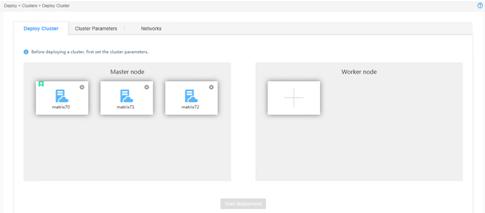
3. Add the other two master nodes in the same way the first master node is added.
For standalone deployment, skip this step.
Figure 14 Master node configuration completed
4. Click Start deployment.
Figure 15 Deployment in process
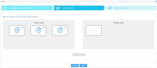
When the deployment progress of each node
reaches 100%, the deployment finishes. Figure 16
shows the cluster deployment. The tile that has a star
icon ![]() at the left corner represents the primary
master node.
at the left corner represents the primary
master node.
Figure 16 Cluster deployment completed
5. Click Next.
The page that opens displays the content of the decoded SNA Center installation package obtained by the SNA Installer platform automatically.
Installing SNA Center
1. Click Next to enter the configuration page.
Figure 17 Installing SNA Installer applications
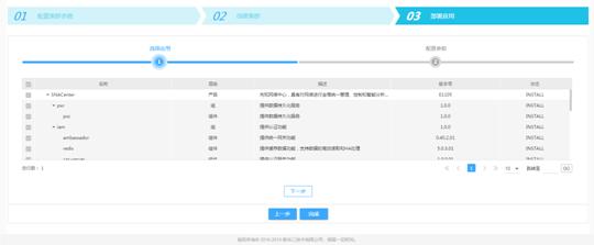
2. Configure the parameters as needed.
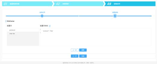
¡ To configure the login protocol for SNA Center, select the Protocol configuration item.
- To use the HTTP protocol for login, enter http. The port number is 10080.
- To use the HTTPS protocol for login, enter https. The port number is 10443.
The login protocol can be configured only during the SNA Center deployment process and cannot be changed after the deployment.
Figure 18 Login protocol configuration
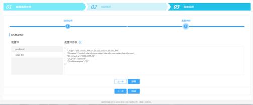
¡ To configure big data-related parameters, select the snac-be configuration item and then configure the parameters. See Table 7 for the parameter descriptions.
Figure 19 Big data-related parameter configuration
|
Item |
Description |
|
DCIps |
Specify the IP addresses of the Big Data cluster nodes 1, 2, and 3. Use commas to separate the IP addresses. |
|
DCnames |
Specify the domain names of the Big Data cluster nodes 1, 2, and 3. Use commas to separate the domain names. |
|
DC_virtual_ip |
Specify the virtual IP address of the Big Data cluster (IP address of the primary master node). |
|
DC_pwd |
Specify the password for logging in to the Big Data cluster through SSH. |
|
DCsshServerport |
Specify the SSH service port for the Big Data cluster. |
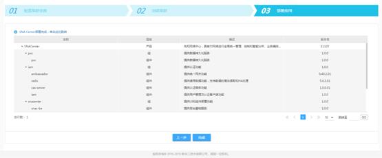
3. Click Deploy.
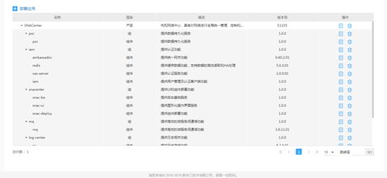
The page displays that SNA Center has been deployed after the deployment finishes. You can click the link to access the SNA Center login page or click Completed to enter the SNA Installer application list. The application list displays information about deployed components, as shown in Figure 21.
Figure 20 Component deployment completed
Logging in to SNA Center
1. Enter http://sna_center_ip_address: 10080/portal/ or https://sna_center_ip_address:10443/portal/ in the address bar and then press Enter.
¡ sna_center_ip_address represents the VIP of the SNA Installer cluster.
¡ 10080 and 10443 are port numbers. If the HTTP login protocol is specified, the port number is 10080. If the HTTPS login protocol is specified, the port number is 10443.
Figure 22 SNA Center login page
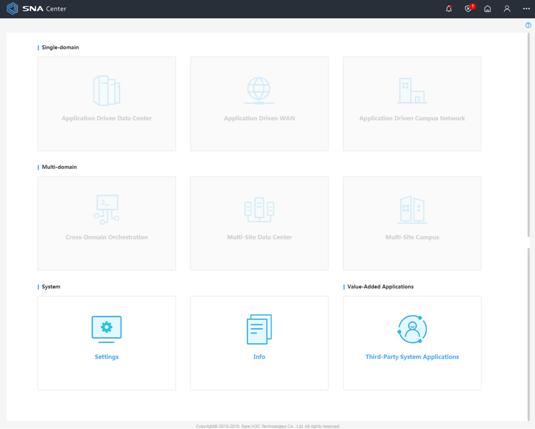
2. Select a language, enter the username and password, and then click Log in.
The default username is admin and the default password is admin@h3c.
Figure 23 SNA Center homepage
Registering SNA Center
After you install SNA Center, you can use complete features and functions of SNA Center for a 180-day trial period. After the trial period expires, you must get your SNA Center licensed.
To register SNA Center:
1. Log in to the license server and obtain the device information file for the license server.
2. Log in to the H3C website and use the license keys and device information file to apply for license files.
3. Upload the license files to the license server and connect SNA Center to the license server.
|
|
NOTE: A license file might become invalid if the following hardware changes occur on the server: · NIC forbidden for use, new NIC start, NIC replacement, or NIC damage. · CPU replacement. |
Obtaining the device information file
1. Enter http://license_ip_address:8090/ in the address bar and then press Enter. If HA is not configured, license_ip_address represents the IP address of the server that hosts the license server. If HA is configured, license_ip_address represents the virtual IP address or the IP address of the master license server.
2. Select a language, enter the username and password, and then click Login.
The default username is admin and the default password is admin@h3c.
3. Select License Management > License Files.
4. On the License Files page, click Export DID.
Applying for license files
To apply for a license file for SNA Center for the first time, see "Registering a license for the first time." For any subsequent license file applications, see "Registering an upgrade license."
A license key is required for each license file application.
Registering a license for the first time
1. Go to the H3C website at http://www.h3c.com.hk/Technical_Support___Documents/Product_Licensing/ and select Register the First Time.
2. From the Product category list, select New Network_H3C SNA Center.
3. Provide the license, device, and contact information as described in Table 8.
|
Item |
Description |
|
License information |
Enter the license key. |
|
Device information |
Upload the device information file. |
|
Contact information |
Enter your contact information. Items marked with an asterisk (*) are required. |
4. Enter the verification code and select I accept all terms of H3C Legal Statement, and then click Get activation key or file.
5. Save the activation file to the PC.
Registering an upgrade license
1. Go to the H3C Website at http://www.h3c.com.hk/Technical_Support___Documents/Product_Licensing/ and select Register Upgrade Licenses.
2. From the Product category list, select New Network_H3C SNA Center.
3. Provide the license, device, and contact information as described in Table 9.
|
Item |
Description |
|
Device information |
Upload the device information file. |
|
License information |
Enter the license key. |
|
Contact information |
Enter your contact information. Items marked with an asterisk (*) are required. |
4. Enter the verification code and select I accept all terms of H3C Legal Statement, and click Get activation key or file.
5. Save the activation file to the PC.
Licensing
1. Upload the license files to the license server and add a license client.
a. Log in to the license server. Select License Management > License Files.
b. On the License Files page, click Install license file.
c. In the dialog box that opens, click Browse… to select the license files saved locally. Then, click OK.
After the license files are uploaded, licensing information is displayed on the License Files page.
d. Select Configuration > License Clients. On the page that opens, click Add.
e. Enter client information such as client name and password, and then click OK.
2. Log in to SNA Center to obtain licensing information.
a. Click Settings on the top navigation bar and then select License from the left navigation pane.
b. In the License Server Info area, provide the IP address, username, password, and port number as described in Table 10.
Table 10 License server information
|
Item |
Description |
|
IP address |
Specify the IP address configured on the license server used for internal communication in the SNA Installer cluster. |
|
Port number |
Specify the service port number of the license server. The default value is 5555. |
|
Username |
Specify the username configured on the license server. |
|
Password |
Specify the user password configured on the license server. |
c. Click Connect to connect the controller to the license server.
SNA Center automatically obtains licensing information after connecting to the license server.
Managing SNA Center components
|
|
IMPORTANT: You can deploy, upgrade, and uninstall SNA Center components only on SNA Center. |
Different scenarios require different components. This section uses the Layer 2 campus network scenarios to illustrate the procedures.
Deploying components
Preparing for deployment
1. Use Table 11 to identify the required components.
Table 11 Required components for each scenario
|
Scenario |
Component |
Component installation package |
|
Campus network |
VCFC-Campus |
VCFC-CAMPUS-version-MATRIX.zip |
|
vDHCP Server |
vDHCPS-version-X64.zip |
|
|
Super controller |
Super Controller |
SUPER_CONTROLLER-version.zip |
|
Cloud DC |
VCFC-DataCenter |
VCFC_DC-version-MATRIX.zip |
|
vDHCP Server |
vDHCPS-version-X64.zip |
|
|
WAN |
VCFC-WAN |
VCFCWAN-version.zip |
|
Config Channel (optional) |
ConfigChannel-version.zip |
|
|
vDHCP Server (optional) |
vDHCPS-version-X64.zip |
|
|
Intelligent Analysis Engine |
SeerAnalyzer |
SEERANALYZER-version-MATRIX.zip |
|
Config Channel |
ConfigChannel-version.zip |
|
|
Campus network + Intelligent Analysis Engine |
Oasis Platform |
oasis-version.zip |
|
|
NOTE: · version in an installation package name represents the software version number. · Cloud DC and WAN scenarios are not supported in the current software version. |
2. To deploy the SeerAnalyzer component, modify the configuration file to configure big data-related parameters if you did not specify the parameters during SNA deployment. For more information about the parameters to specify, see step 2 in " Installing SNA Center."
3. Enable Ethernet adapters on the server that hosts SNA Center. For the Layer 2 campus network scenarios, you must enable two Ethernet adapters. For any other scenarios, enable only one Ethernet adapter.
To enable an Ethernet adapter:
a. Access the server that hosts SNA Center remotely.
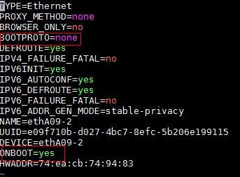
b. Access the configuration file of an Ethernet adapter. This procedure uses Ethernet adapter ens34 as an example.
[root@sna001 /]# vi /etc/sysconfig/network-scripts/ifcfg-ens34
c. Set the BOOTPROTO field to none to specify no boot-time protocol and set the ONBOOT field to yes to activate the Ethernet adapter at system startup.
Figure 24 Modifying the configuration file of an Ethernet adapter
d. Execute the ifdown and ifup commands in sequence to reboot the Ethernet adapter.
[root@sna001 /]# ifdown ens34
[root@sna001 /]# ifup ens34
e. Execute the ifconfig command to verify that the Ethernet adapter is in UP state.
Deploying a component
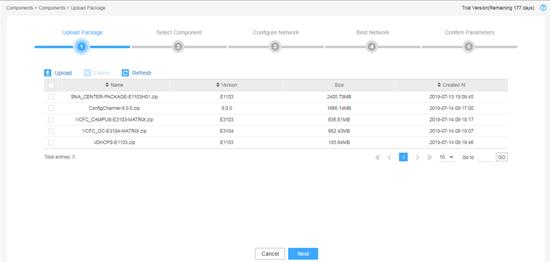
Uploading the component installation package
1. Log in to SNA Center, click Settings, and then select Components > Components.
2. Click Upload to upload the component installation package and then click Next.
Figure 25 Uploading the component installation package
Selecting a component
Select the component to be installed, configure the other settings as required, and then click Next.
Figure 26 Selecting a component (1)
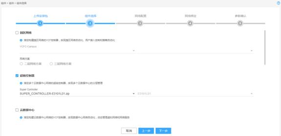
Figure 27 Selecting a component (2)
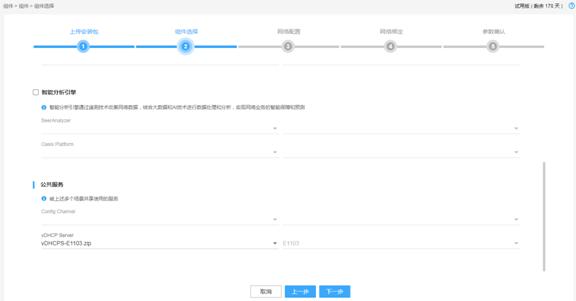
Table 12 Component description
|
Item |
Description |
Remarks |
|
Campus network |
Specify the VCF controller for setting up a campus network to implement campus network automation, user access control automation, and policy automation. |
You must specify a network scheme. |
|
Layer 2 network scheme |
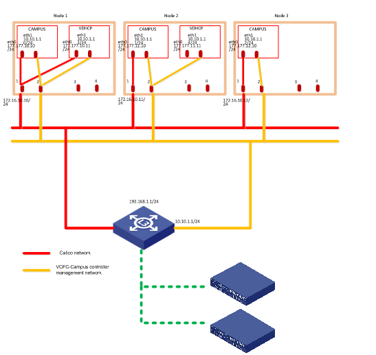
Enables automatically deployed devices to communicate with the VCFC-Campus controller at Layer 2. The controller can use devices' IP addresses to manage the devices automatically. |
You must configure a management network and a default network. For information about the network diagram, see Figure 28. |
|
Layer 3 network scheme |
Enables automatically deployed devices to communicate with the VCFC-Campus controller at Layer 3. |
You must configure routes in the automated device association template to enable online devices to reach the controller in the management network. For information about the network diagram, see Figure 29. |
|
Super controller |
Specify the super controller for multiple cloud DC networks for hierarchical management of these networks. |
You must specify a super controller version. |
|
Cloud DC |
Specify the VCF controller for setting up a cloud DC network to implement DC network automation and dynamically manage virtual networks and network services. |
N/A |
|
WAN |
Specify the VCF controller for setting up a WAN to implement service automation and intelligent traffic scheduling for WAN backbone networks, vertical networks, and branch networks. |
N/A |
|
Intelligent Analysis Engine |
Specify the intelligent analysis engine, which collects network data through telemetry technologies, and analyzes and processes the data through big data and AI to implement intelligent assurance and prediction for network services. |
N/A |
|
Public Service |
Specify services shared by multiple scenarios mentioned above. Options include Config Channel and vDHCP server. vDHCP Server is used for automated device deployment. SNA Center deploys a dual-node cluster for the vDHCP servers based on the predefined policies. |
N/A |
Figure 28 Layer 2 campus network
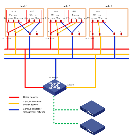
Figure 29 Layer 3 campus network
Configuring network settings
1. Determine the number of networks and subnets to be created.
¡ For the Layer 2 campus network, create two networks, one as the management network and the other as the default network.
¡ For the Layer 3 campus network, cloud DC, and WAN, create one network.
¡ For the super controller and Intelligent Analysis Engine, no network is required. Click Next to proceed to the next step.
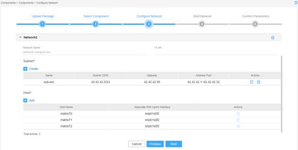
2. Create networks and subnets and configure network settings.
If you create different networks that use the same uplink interface, configure different VLANs for the networks to isolate network traffic.
The subnet address range and address pool are used to assign IP addresses to components. Make sure the address range of each subnet contains a minimum of 32 addresses. As a best practice, use Table 13 to determine the address pool size for a subnet.
Table 13 Number of IP addresses required for a subnet
|
Component |
Number of default network's IP addresses |
Number of management network's IP addresses |
Maximum cluster members |
Default cluster members |
|
VCFC-Campus |
Number of cluster members + 1 (secondary cluster IP) |
Number of cluster members + 1 (cluster IP) |
32 |
3 |
|
VCFC-DataCenter |
N/A |
32 |
3 |
|
|
VCFC-WAN |
N/A |
5 |
3 |
|
|
vDHCP Server |
Number of cluster members |
2 |
2 |
The total number of IP addresses required for a subnet is the sum of IP addresses required by all components for the subnet scenario. For information about components for a scenario, see Table 11.
For example, to deploy a Layer 2 campus network, if the VCFC-Campus cluster has 32 members and the vDHCP cluster has 2 members, the number of required IP addresses for a subnet is as follows:
¡ For a default network subnet: 32 + 1 + 2=35.
¡ For a management network subnet: 32 + 1 + 3=36.
3. Click Next.
Figure 30 Configuring network settings (1)
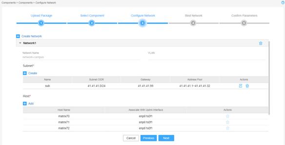
Figure 31 Configuring network settings (2)
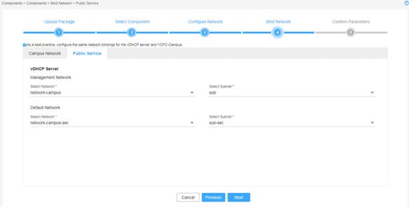
Binding networks
Bind networks to the components and then click Next.
|
|
IMPORTANT: · For vDHCP services to be used by the campus network, specify the same management network, default network, and subnets for the VCFC-Campus and the vDHCP components. · In a cloud DC scenario, to deploy the VCFC-DataCenter and vDHCP components on different networks, you must specify a management network for each of the two components and ensure Layer 3 reachability between the two components. |
Figure 32 Binding networks to components (1)
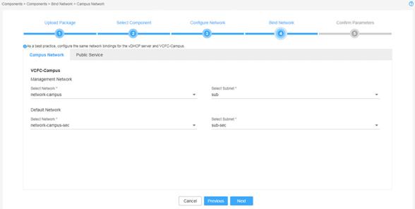
Figure 33 Binding networks to components (2)
Verifying the configuration
On the page that opens, verify that the component settings are correct, and then click Deploy.
A component automatically gets an IP address from the IP address pool of the subnet bound to it. To modify the IP address, click Modify and then specify another IP address for the component. The IP address specified must be in the IP address range of the subnet bound to the component.
Figure 34 Verifying the configuration (1)
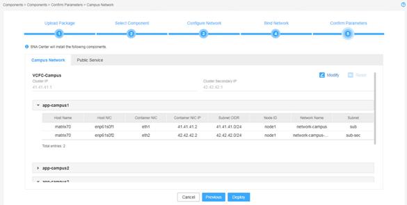
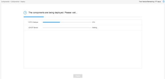
The system starts to deploy the components. For a Layer 2 campus network, the system assigns an IP address in the management network as the primary cluster IP and an IP address in the default network as the secondary cluster IP. For a Layer 3 campus network or a cloud DC network, the system assigns an IP address in the management network as the primary cluster IP.
The page displays the deployment progress as shown in Figure 35.
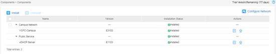
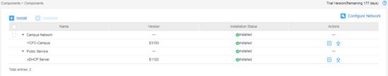
Viewing deployed component information
1. Select Components > Components.
2.
Click the right chevron button ![]() to expand component
information.
to expand component
information.
Figure 36 Deployed component list
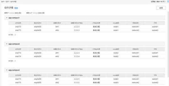
3.
To view detailed information, click the ![]() icon for the target
component.
icon for the target
component.
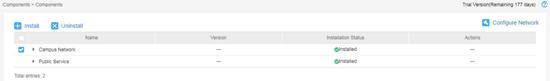
Upgrading a component
1. Log in to SNA Center and then select Components > Components.
Figure 38 Deployed component list
2.
Click the right chevron button ![]() for the target component to expand component
information, and then click the upgrade icon
for the target component to expand component
information, and then click the upgrade icon ![]() .
.
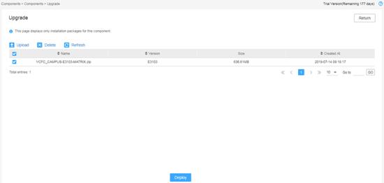
3. Upload the installation package.
4. Select the package and then click Deploy.
Figure 39 Select an installation package for upgrade
5. If the upgrade fails, click Roll Back to roll back to the previous version.
Uninstalling a component
1. Log in to SNA Center and select Components > Components.
2.
Select the target component and then click ![]() .
.
Figure 40 Uninstalling a component
Backing up and restoring SNA Center configuration
|
|
CAUTION: · Do not perform any configuration operations while a configuration backup or restoration process is in progress. · To ensure configuration consistency, you must use the backup files of SNA Installer, SNA Center, and SNA center components saved at the same time for restoration. As a best practice, use the backup files saved at the same scheduled time for configuration restoration. |
You can back up and restore configurations for SNA Center and its components.
· Backup—The system supports scheduled backup and manual backup. You can back up the file to the server where SNA Center resides or a remote server, or save the file locally. The file must be named in the prefix name_product name_product version_date_backup mode.zip format. The backup mode can be M or A, representing manual backup or scheduled backup respectively.
· Restore—You can restore the product configuration from the local backup file or from the backup history list.
Backing up the configuration
1. Log in to SNA Center.
2. Click Settings in the System area and then click the Backup & Restore tab.
3. Click Backup Configuration. On the dialogue box that opens, configure the backup settings, including the prefix name of the backup file and parameters for local backup, remote backup, and scheduled backup, and then click Apply.
If you enable the scheduled backup option, the system automatically backs up the configurations of all components to the specified path at the scheduled interval.
4. Click Back up and then select a product to back up.
Restoring the configuration
1. Log in to SNA Center.
2. Click Settings in the System area and then click the Backup & Restore tab.
3. Choose one of the following methods to restore the configuration:
¡ Restoring the configuration from a backup file saved locally
# Click the ![]() icon to select the backup file, and then click Upload. If a
"Operate successed" message is displayed, the file is uploaded successfully.
icon to select the backup file, and then click Upload. If a
"Operate successed" message is displayed, the file is uploaded successfully.
# Click Restore.
¡ Restoring the configuration from the Backup History list.
# Determine the backup file. Click Restore in the Actions column for the file.
Scaling out SNA Center and its components
|
|
CAUTION: Before scaling out SNA Center and its components, back up the configuration and data of SNA Installer, SNA Center, and SNA Center components. You can use the backup file to restore the configuration and data in case of a scale-out failure. |
Both SNA Center in standalone mode and in cluster mode can be scaled out.
· To scale out SNA Center from standalone mode to cluster mode, add two master nodes on SNA Installer to form a three-host cluster with the existing master node. Then scale out SNA Center and its components sequentially.
· To scale out SNA Center in cluster mode, scale out the nodes one by one.
Scaling out SNA Center in standalone mode
Scaling out SNA Installer
1. Install SNA Installer on two new servers. For the deployment procedure, see "Installing the H3Linux operating system and SNA Installer platform on a server."
2. Add two master nodes to SNA Installer.
a. Log in to SNA Installer.
b. Click Deploy on the top navigation bar and then select Cluster from the navigation pane.
c. In the Master node area, click the plus icon to add two master nodes.
3. Click Start deployment.
The scale out takes some time to complete.
Scaling out SNA Center
1. Log in to SNA Installer.
2. Click Deploy on the top navigation bar and then select Application from the navigation pane.
3. Click Scale out Application and then select SNA Center to scale out.
To deploy the Intelligent Analysis Engine, configure related parameters. For the parameter description, see Table 7.
|
|
IMPORTANT: To avoid SNA Center access failure, do not modify the setting of the Protocol configuration item. |
Figure 41 SNA Installer application list

Scaling out a component
Before scaling out a component, make sure SNA Center has been scaled out to cluster mode.
To scale out a component:
1. Log in to SNA Center.
2. Click Settings in the System area.
3. Click Components on the top navigation bar and then select Components on the left pane.
4.
Identify the component to scale out and then
click the Scale Out icon ![]() in the Actions column for the component.
in the Actions column for the component.
5. Select the hosts for the scale out and select the uplink interfaces for each host. Then click OK.
Figure 42 Selecting hosts for the scale out
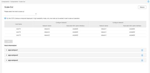
6. Confirm the post-scale out cluster information in the Host Information area and then click Scale out.
You can modify NIC IP addresses in a pod.
Scaling out SNA Center in cluster mode
Scaling out SNA Installer
1. Deploy SNA Installer on the new server. For the deployment procedure, see "Installing the H3Linux operating system and SNA Installer platform on a server."
2. Add a worker node to SNA Installer.
Only one worker node can be added in each scale-out operation.
a. Log in to SNA Installer.
b. Click Deploy on the top navigation bar and then select Cluster from the navigation pane.
c. In the Worker node area, click the plus icon to add a worker node.
3. Click Start deployment.
The scale-out takes some time to complete.
Scaling out a component
Before scaling out a component, make sure SNA Installer, SNA Center, and the component are in cluster mode and a worker node has been added to SNA Installer,.
To scale out a component:
1. Log in to SNA Center.
2. Click Settings in the System area.
3. Click Components on the top navigation bar and then select Components from the left navigation pane.
4.
Identify the component to scale out and then
click the Scale Out icon ![]() in the Actions column for the component.
in the Actions column for the component.
5. Select the hosts for the scale out and select the uplink interfaces for each host. Then click OK.
6. Confirm the post-scale out cluster information in the Host Information area and then click Scale out.
You can modify NIC IP addresses in a pod.
(Optional) Removing a scaled-out instance
Only the VCFC-Campus controller supports removing a scaled-out instance, and only an instance scaled out from a cluster can be removed.
To remove a scaled-out instance:
1. Log in to SNA Center.
2. Click Settings in the System area.
3. Click Components on the top navigation bar and then select Components from the navigation pane.
4.
Identify the instance .Click the ![]() icon for the instance and then click OK in the confirmation dialog box that opens.
icon for the instance and then click OK in the confirmation dialog box that opens.
Removing a deployed instance might affect the services. Back up the instance before removing it.
Uninstalling SNA Center
1. Log in to SNA Installer platform.
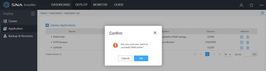
2. Select Deploy from the top navigation bar and then select Application from the left navigation pane.
3.
Click the ![]() icon for the SNA Center
application.
icon for the SNA Center
application.
4. In the confirmation dialog box that opens, click OK.
Figure 43 Uninstalling SNA Center
Upgrading the software
This chapter describes procedures for upgrading SNA Center, SNA Installer, and H3Linux OS. You can upgrade SNA Installer alone or upgrade it together with the H3Linux OS.
Upgrading SNA Installer does not affect operation of SNA Center.
Upgrading SNA Center
To upgrade SNA Center, you must uninstall the existing SNA Center and then install the new version. This operation retains SNA Center configuration and the deployed SNA Center components are still available after the upgrade.
To upgrade SNA Center:
1. Log in to SNA Installer and uninstall the existing SNA Center. For more information, see "Uninstalling SNA Center."
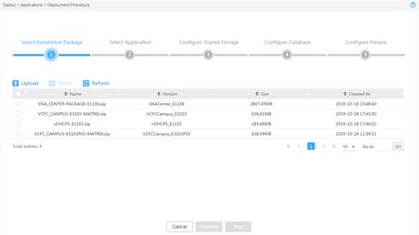
2. Select Deploy from the top navigation bar and then select Application from the left navigation pane.
3.
Click the ![]() icon to upload the
new version of the SNA Center installation package.
icon to upload the
new version of the SNA Center installation package.
The uploaded package will be displayed on the Deployment Procedure page.
Figure 44 Deployment process page
4. Install the new version SNA Center. For more information, see " Installing SNA Center."
Upgrading the SNA Installer platform
|
|
IMPORTANT: · For correct operation of SNA Installer, do not power off or reboot the server that hosts SNA Installer during the upgrade process. · In cluster mode, SNA Installer supports In-Service Software Upgrade (ISSU) to ensure service continuity. · In standalone mode, SNA Installer does not support ISSU. To upgrade SNA Installer in standalone mode, first back up data and then install the new version of SNA Installer. For the installation procedure, see "Upgrading the H3Linux OS and SNA Installer." |
|
|
IMPORTANT: To upgrade SNA Installer in cluster mode, upgrade the secondary master nodes before the primary master node. Services on a master node to be upgraded are migrated to another master node not disabled. To avoid service interruption, upgrade the master nodes one by one. |
The SNA Installer upgrade procedure differs depending on its current version and target version.
To upgrade SNA Installer:
1. Determine the current version of SNA Installer.
a. Log in to SNA Installer.
b.
Click the ![]() icon in the upper
right corner and then select About
SNA Installer. The version of SNA Installer is
displayed on the dialogue box that opens.
icon in the upper
right corner and then select About
SNA Installer. The version of SNA Installer is
displayed on the dialogue box that opens.
2. Obtain the ISO image file of the new version and decompress the matrix-version.rpm SNA Installer installation package.
3. Upgrade SNA Installer.
a. (Optional.) Execute the pre-upgrade script file. See "Executing the pre-upgrade script."
- To upgrade SNA Installer to V500R001B05D001 or later from an earlier version, first execute the matrix_B05_preupdate.sh pre-upgrade script file. In case of an upgrade failure, you can re-perform the upgrade or roll back the configuration. To roll back the configuration, see "Appendix A Troubleshooting."
- To upgrade SNA Installer to a version earlier than V500R001B05D001 or from V500R001B05D001 to a later version, skip this step.
|
|
NOTE: After you upgrade SNA Installer on a node in cluster mode to V500R001B05D001 or later, the default username and password for logging in to SNA Installer are still admin and matrix123, respectively. |
b. Upgrade SNA Installer by using either of the following methods:
- Uploading the image—Upgrade through image uploading from the Web interface. You can use this method to upgrade only secondary master nodes. To upgrade a primary master node by using this method, first switch the primary master node to a secondary node.
- Re-installing the platform—Upload through platform reinstallation from the CLI. You can use this method to upgrade any master node.
Executing the pre-upgrade script
To upgrade SNA Installer to V500R001B05D001 or later from an earlier version, first execute the matrix_B05_preupdate.sh pre-upgrade script file. To upgrade SNA Installer to a version earlier than V500R001B05D001 or from V500R001B05D001 to a later version, skip this procedure.
To execute the pre-upgrade script:
1. Obtain the matrix_B05_preupdate.sh pre-upgrade script file. Then copy the file or use a file transfer protocol, FTP for example, to transfer the file to the installation directory on the server.
2. Execute the ./matrix_B05_preupdate.sh command to run the pre-upgrade script file.
[root@matrix01 ~]# ./matrix_B05_preupdate.sh
found image multus:v3.1_fix on local node...
created a new tag matrix/multus:v3.1_fix refs to multus:v3.1_fix
Login Succeeded
logged in to harbor regsitry...
…
patched multus daemonset to use image matrix/multus:3.2.0.1
the execution of B05 preupdate script has completed successfully!!!
|
|
NOTE: You only need to execute the pre-upgrade script file on one node. |
Uploading the image
1. Log in to SNA Installer. Click Deploy on the top navigation bar and then select Cluster from the navigation pane.
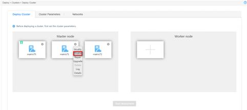
2.
Click the set icon
![]() for the target node, and then select Upgrade.
for the target node, and then select Upgrade.
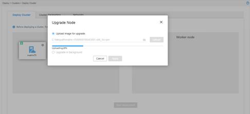
3. In the dialog box than opens, select Upload image for upgrade.
Figure 45 Selecting an upgrade method
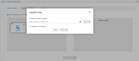
4. Select the matrix-version.rpm image file, and then click Upload. After the upload is complete, click Apply to start the upgrade.
Figure 46 Uploading the image file
The node icon turns to blue when the upgrade succeeds.
Figure 47 Upgrade completed
5.
Click the ![]() icon at the upper
right corner of the page and then select About SNA Installer to verify that SNA
Installer has been upgraded successfully.
icon at the upper
right corner of the page and then select About SNA Installer to verify that SNA
Installer has been upgraded successfully.
Re-installing the platform
Disabling a node to be upgraded
1. Log in to SNA Installer. Click Deploy on the top navigation bar and then select Cluster from the navigation pane.
2.
Click the set icon ![]() for the
target node, and then select Disable.
for the
target node, and then select Disable.
Figure 48 Disabling a node
Upgrading a disabled node
1. Access the CLI of the node that hosts SNA Installer.
2. Uninstall SNA Installer.
[root@sna001 ~]# rpm -e matrix
3. Copy or use a file transfer protocol (for example, FTP) to upload the matrix-version.rpm image file to the target directory on the node. The directory is /root in this example.
4. Access the storage directory of the image file and execute the rpm -ivh matrix-version.rpm command. The version number is V500R001B04D001.x86_64 in this example.
[root@sna001 ~]# rpm -ivh matrix-V500R001B04D001.x86_64.rpm
Preparing... ################################# [100%]
Updating / installing...
1:matrix-V500R001B04D001-1 ################################# [100%]
Complete!
5. Execute the systemctl status matrix command to view the installation result. The installation succeeds if the active state is active (running).
[root@sna001 ~]# systemctl status matrix
matrix.service - Matrix Server
Loaded: loaded (/usr/lib/systemd/system/matrix.service; enabled; vendor preset: disabled)
Active: active (running) since Sat 2019-06-29 01:15:21 CST; 2min 23s ago
Main PID: 29028 (karaf)
...
Enabling an upgraded node
1. Log in to SNA Installer.
2. Click Deploy on the top navigation bar and then select Cluster from the navigation pane.
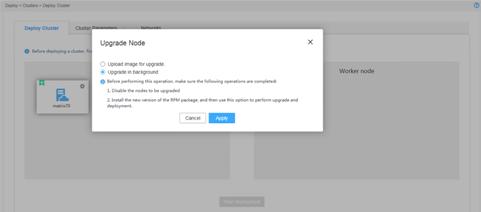
3.
Click the set icon ![]() for the
target node, and then select Upgrade. In the dialog
box that opens, select Upgrade in background
and then click Apply.
for the
target node, and then select Upgrade. In the dialog
box that opens, select Upgrade in background
and then click Apply.
Figure 49 Upgrading a node
4.
Click the set icon ![]() for the
node, and then select Enable. The node icon turns to blue when the upgrade succeeds.
for the
node, and then select Enable. The node icon turns to blue when the upgrade succeeds.
Figure 50 Upgrade completed

5.
Click the ![]() icon at the upper
right corner of the page and select About SNA Installer to verify that SNA
Installer has been upgraded successfully.
icon at the upper
right corner of the page and select About SNA Installer to verify that SNA
Installer has been upgraded successfully.
Upgrading the H3Linux OS and SNA Installer
1.
Log in to SNA Installer. Click Deploy on the
top navigation bar and then select Cluster from the navigation pane.
Click the set icon ![]() for the target node, and then select Disable to
disable the node.
for the target node, and then select Disable to
disable the node.
2. Obtain the ISO image file and reinstall the H3Linux OS and SNA Installer platform. For more information, see "Installing SNA Center and its components."
3.
From the SNA Installer GUI, click Deploy on the
top navigation bar and then select Cluster from the navigation pane.
Click the set icon ![]() for the target node, and then select Upgrade to upgrade the node.
for the target node, and then select Upgrade to upgrade the node.
4.
After the upgrade finishes, click the set
icon ![]() for the node, and then select Enable to enable the node.
for the node, and then select Enable to enable the node.
5.
Click the ![]() icon at the upper
right corner of the page and select About SNA Installer to verify that SNA
Installer has been upgraded successfully.
icon at the upper
right corner of the page and select About SNA Installer to verify that SNA
Installer has been upgraded successfully.
|
|
NOTE: If you use the SNA_CENTER-PACKAGE-E1105 ISO image file to upgrade H3Linux OS and SNA Installer on a node in cluster mode, the default username and password for logging in to SNA Installer after upgrade are still admin and matrix123, respectively. |
Appendix A Troubleshooting
Failed to upgrade SNA Installer to V500R001B05D001 or later from an earlier version
Symptom
The system failed to upgrade SNA Installer to V500R001B05D001 or later from an earlier version.
Solution
To resolve the issue, re-upgrade the node or roll back the configuration as follows:
1. Obtain the matrix_B05_preupdate_rollback.sh rollback script file.
2. Copy the file or use the file transfer protocol, FTP for example, to transfer the file to the installation directory on the server.
3. Execute the ./matrix_B05_preupdate_rollback.sh command to run the rollback script file.
[root@matrix01 ~]# ./matrix_B05_preupdate_rollback.sh
daemonset.extensions/kube-multus-ds-amd64 patched
patched multus daemonset to use image matrix/multus:v3.1_fix
the rollback of B05 preupdate script has completed successfully!!!
4. If the issue persists, contact the support.
|
|
NOTE: To continue the upgrade after an upgrade failure, you are not required to execute the script file. |
Appendix B SNA Center software dependencies
Table 14 SNA Center software dependencies
|
Software name |
Software version |
|
java openjdk |
1.8.0 |
|
zip |
3.0 |
|
unzip |
6.0 |
|
tar |
1.26-34.el7.x86_64 |
|
chrony |
3.2-2 |
|
ntpdate |
4.2.6p5 |
|
docker-client |
1.13.1 |
|
docker-common |
1.13.1 |
|
docker |
1.13.1 |
