- Table of Contents
-
- 09-Security Configuration Guide
- 00-Preface
- 01-AAA configuration
- 02-Password control configuration
- 03-Public key management
- 04-PKI configuration
- 05-SSL configuration
- 06-IPsec configuration
- 07-SSH configuration
- 08-IP source guard configuration
- 09-ARP attack protection configuration
- 10-uRPF configuration
- 11-FIPS configuration
- 12-Attack detection and prevention configuration
- Related Documents
-
| Title | Size | Download |
|---|---|---|
| 10-uRPF configuration | 187.65 KB |
Configuring uRPF
Overview
Unicast Reverse Path Forwarding (uRPF) protects a network against source address spoofing attacks, such as DoS and DDoS attacks.
Attackers send packets with a forged source address to access a system that uses IP-based authentication, in the name of authorized users or even the administrator. Even if the attackers or other hosts cannot receive any response packets, the attacks are still disruptive to the attacked target.
Figure 1 Source address spoofing attack
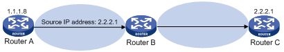
As shown in Figure 1, an attacker on Router A sends the server (Router B) requests with a forged source IP address 2.2.2.1 at a high rate, and Router B sends response packets to IP address 2.2.2.1 (Router C). Consequently, both Router B and Router C are attacked. If the administrator disconnects Router C by mistake, the network service is interrupted.
Attackers can also send packets with different forged source addresses or attack multiple servers simultaneously to block connections or even break down the network.
uRPF can prevent these source address spoofing attacks. It checks whether an interface that receives a packet is the output interface of the FIB entry that matches the source address of the packet. If not, uRPF considers it a spoofing attack and discards the packet.
uRPF check modes
uRPF supports strict and loose modes.
· Strict uRPF check—To pass strict uRPF check, the source address of a packet and the receiving interface must match the destination address and output interface of a FIB entry. In some scenarios (for example, asymmetrical routing), strict uRPF might discard valid packets. Strict uRPF is often deployed between a PE and a CE.
· Loose uRPF check—To pass loose uRPF check, the source address of a packet must match the destination address of a FIB entry. Loose uRPF can avoid discarding valid packets, but might let go attack packets. Loose uRPF is often deployed between ISPs, especially in asymmetrical routing.
uRPF operation
Figure 2 shows how uRPF works.
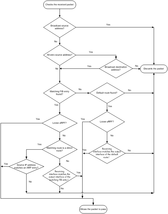
1. uRPF checks source address validity:
¡ Discards packets with a source broadcast address.
¡ Discards packets with an all-zero source address but a non-broadcast destination address. (A packet with source address 0.0.0.0 and destination address 255.255.255.255 might be a DHCP or BOOTP packet and cannot be discarded.)
¡ Proceeds to step 2 for other packets.
2. uRPF checks whether the source address matches a FIB entry:
¡ If yes, proceeds to step 3.
¡ If no, proceeds to step 6.
3. uRPF checks whether the check mode is loose:
¡ If yes, proceeds to step 8.
¡ If no, uRPF checks whether the matching route is a direct route:
- If yes, proceeds to step 5.
- If no, proceeds to step 4.
4. uRPF checks whether the receiving interface matches the output interface of the matching FIB entry:
¡ If yes, proceeds to step 8.
¡ If no, proceeds to step 9.
5. uRPF checks whether the source IP address matches an ARP entry:
¡ If yes, proceeds to step 8.
¡ If no, proceeds to step 9.
6. uRPF checks whether the FIB table has a default route:
¡ If yes, proceeds to step 7.
¡ If no, proceeds to step 9.
7. uRPF checks whether the check mode is loose:
¡ If yes, proceeds to step 8.
¡ If no, uRPF checks whether the output interface of the default route matches the receiving interface of the packet:
- If yes, proceeds to 8
- If no, proceeds to 9.
8. The packet passes the check and is forwarded.
9. The packet is discarded.
|
|
NOTE: uRPF does not check multicast packets. |
Network application
Figure 3 Network diagram

Configure strict uRPF check between an ISP network and a customer network, and loose uRPF check between ISPs.
Configuration procedure
uRPF checks only incoming packets on interfaces. You can enable uRPF globally or on an interface. Global uRPF takes effect on all interfaces of the device. uRPF enabled on an interface takes effect only on the interface. If you enable uRPF globally and on an interface, the interface preferentially uses the interface-specific settings.
When you enable uRPF, follow these restrictions and guidelines:
· FC service modules do not support uRPF configuration in interface view.
If strict uRPF is enabled globally, the VLAN interfaces perform strict uRPF, but the following interfaces do not perform uRPF check:
¡ Layer 3 Ethernet interfaces.
¡ Layer 3 Ethernet subinterfaces.
¡ Layer 3 aggregate interfaces.
¡ Layer 3 aggregate subinterfaces.
If loose uRPF is enabled globally, all interfaces perform loose uRPF.
· FX and FE service modules support both loose and strict uRPF on VLAN interfaces. FX and FE service modules support only loose uRPF on the following interfaces:
¡ Layer 3 Ethernet interfaces.
¡ Layer 3 Ethernet subinterfaces.
¡ Layer 3 aggregate interfaces.
¡ Layer 3 aggregate subinterfaces.
If strict uRPF is enabled globally or on these interfaces, the interfaces still perform loose uRPF.
To enable uRPF globally:
|
Step |
Command |
Remarks |
|
1. Enter system view. |
system-view |
N/A |
|
2. Enable uRPF globally. |
ip urpf { loose | strict } |
By default, uRPF is disabled. |
To enable uRPF on an interface:
|
Step |
Command |
Remarks |
|
1. Enter system view. |
system-view |
N/A |
|
2. Enter interface view. |
interface interface-type interface-number |
The following interface types are supported: · Layer 3 Ethernet interface. · Layer 3 Ethernet subinterface. · Layer 3 aggregate interface. · Layer 3 aggregate subinterface. · VLAN interface. |
|
3. Enable uRPF on the interface. |
ip urpf { loose | strict } |
By default, uRPF is disabled. |
Displaying and maintaining uRPF
Execute display commands in any view.
|
Task |
Command |
|
Display uRPF configuration (in standalone mode). |
display ip urpf [ interface interface-type interface-number ] [ slot slot-number ] |
|
Display uRPF configuration (in IRF mode). |
display ip urpf [ interface interface-type interface-number ] [ chassis chassis-number slot slot-number ] |
uRPF configuration example
Network requirements
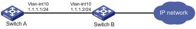
As shown in Figure 4, a client (Switch A) directly connects to an ISP switch (Switch B).
To prevent source address spoofing attacks, perform the following tasks:
· Enable strict uRPF check on Switch A.
· Enable strict uRPF check on VLAN-interface 10 of Switch B.
Configuration procedure
1. Enable strict uRPF check on Switch A.
<SwitchA> system-view
[SwitchA] ip urpf strict
2. Configure Switch B:
# Create VLAN 10.
[SwitchB] vlan 10
[SwitchB-vlan10] quit
# # Specify an IP address for VLAN-interface 10.
[SwitchB] interface vlan-interface 10
[SwitchB-Vlan-interface10] ip address 1.1.1.2 255.255.255.0
# Enable strict uRPF check on VLAN-interface 10.
[SwitchB-Vlan-interface10] ip urpf strict