- Table of Contents
- Related Documents
-
| Title | Size | Download |
|---|---|---|
| 04-Data buffer configuration | 75.56 KB |
Configuring data buffers manually
Configuring the total shared-area ratio
Setting the maximum shared-area ratio for a queue
Setting the fixed-area ratio for a queue
Applying data buffer configuration
Configuring data buffer monitoring
Displaying and maintaining data buffers
Configuring data buffers
An interface stores outgoing packets in the egress buffer when congestion occurs.
An egress buffer uses the following types of resources:
· Cell resources—Store packets. The buffer uses cell resources based on packet sizes. Suppose a cell resource provides 208 bytes. The buffer allocates one cell resource to a 128-byte packet and two cell resources to a 300-byte packet.
· Packet resources—Store packet pointers. A packet pointer indicates where the packet is located in cell resources. The buffer uses one packet resource for each incoming or outgoing packet.
Each type of resources has a fixed area and a shared area.
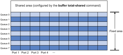
· Fixed area—Partitioned into queues, each of which is equally divided by all the interfaces on a device, as shown in Figure 1. When congestion occurs, the following rules apply:
a. An interface first uses the relevant queues of the fixed area to store packets.
b. When a queue is full, the interface uses the space for the queue in the shared area.
c. When the queue in the shared area is also full, the interface discards subsequent packets.
The system allocates the fixed area among queues as specified by the user. Even if a queue is not full, other queues cannot preempt its space. Similarly, the share of a queue for an interface cannot be preempted by other interfaces even if it is not full.
· Shared area—Partitioned into queues, each of which is not equally divided by the interfaces, as shown in Figure 1. The system determines the actual shared-area ratio for each queue according to user configuration and the number of packets actually sent. If a queue is not full, other queues can preempt its space.
The system puts packets received on all interfaces into a queue in the order they arrive. When the queue is full, subsequent packets are dropped.
Figure 1 Fixed area and shared area
Configuration task list
You can configure data buffers either automatically by enabling the Burst feature or manually.
If you have configured data buffers in one way, delete the configuration before using the other way. Otherwise, the new configuration does not take effect.
To configure the data buffer, perform the following tasks:
|
Tasks at a glance |
|
Perform one of the following tasks: · Configuring data buffers manually ¡ Configuring the total shared-area ratio ¡ Setting the maximum shared-area ratio for a queue |
|
(Optional.) Configuring data buffer monitoring |
Enabling the Burst feature
The Burst feature enables the switch to automatically allocate cell and packet resources. It is well suited to the following scenarios:
· Traffic enters a switch from a high-speed interface and goes out of a low-speed interface.
· Traffic enters a switch from multiple same-rate interfaces and goes out of an interface with the same rate.
To enable the Burst feature:
|
Step |
Command |
Remarks |
|
1. Enter system view. |
system-view |
N/A |
|
2. Enable the Burst feature. |
burst-mode enable |
By default, the Burst feature is disabled. The Burst feature takes effect only on known unicast packets. |
Configuring data buffers manually
|
|
CAUTION: · To avoid impact on the forwarding function of the system, do not manually change data buffer settings. If large buffer spaces are needed, use the Burst feature. · Manually configuring data buffers might cause generic flow control and PFC to operate incorrectly. For more information about generic flow control and PFC, see Layer 2—LAN Switching Configuration Guide. |
The switch only supports configuring cell resources.
Configuring the total shared-area ratio
Each type of resources of a buffer, packet or cell, has a fixed size. After you set the total shared-area ratio for a type of resources, the rest is automatically assigned to the fixed area.
To configure the total shared-area ratio:
|
Step |
Command |
Remarks |
|
system-view |
N/A |
|
|
2. Configure the total shared-area ratio. |
buffer egress [ slot slot-number ] cell total-shared ratio ratio-value |
By default, the total shared-area ratio is 84% of the buffer. |
Setting the maximum shared-area ratio for a queue
By default, all queues have an equal share of the shared area. This task allows you to change the maximum shared-area ratio for a queue. The unconfigured queues use the default setting.
The actual maximum shared-area ratio for each queue is determined by the chip based on your configuration and the number of packets to be sent.
To set the maximum shared-area ratio for a queue:
|
Step |
Command |
Remarks |
|
1. Enter system view. |
system-view |
N/A |
|
2. Set the maximum shared-area ratio for a queue. |
buffer egress [ slot slot-number ] cell queue queue-id shared ratio ratio-value |
The default setting is 33% for each queue. |
For the maximum shared-area ratio for a queue, the percentage values 0 to 100 are divided into 10 ranges. Table 1 shows the effective values that correspond to the configured values of ratio-value.
Table 1 Mapping between values of ratio-value and effective values
|
Value of ratio-value |
Effective value |
|
0 to 1 |
1 |
|
2 to 3 |
3 |
|
6 |
|
|
8 to 16 |
11 |
|
17 to 29 |
20 |
|
30 to 42 |
33 |
|
43 to 60 |
50 |
|
61 to 76 |
67 |
|
77 to 86 |
80 |
|
87 to 100 |
89 |
Setting the fixed-area ratio for a queue
By default, all queues have an equal share of the fixed area. This task allows you to change the fixed-area ratio for a queue. The unconfigured queues equally share the remaining part.
The fixed-area space for a queue cannot be used by other queues. It is also called the minimum guaranteed buffer.
When you set the fixed-area ratio for a queue, follow these restrictions and guidelines:
· The sum of ratios configured for all queues cannot be greater than or equal to 100%. Queues 5, 6, and 7 must have available fixed-area space.
· After you configure the fixed-area ratios for some queues, the other queues each are assigned an equal share of the remaining part of the fixed area. The display buffer queue command displays the preceding whole number for each assignment result. Therefore, the sum of the ratios for all queues might be less than 100%.
To set the fixed-area ratio for a queue:
|
Step |
Command |
Remarks |
|
1. Enter system view. |
system-view |
N/A |
|
2. Set the fixed-area ratio for a queue. |
buffer egress [ slot slot-number ] cell queue queue-id guaranteed ratio ratio-value |
The default setting is 12.5% for each queue, but the default value in the display buffer queue command output is 13%. |
Applying data buffer configuration
Perform this task to apply the data buffer configuration.
You cannot directly modify the applied configuration. To modify the configuration, you must cancel the application, reconfigure data buffers, and reapply the configuration.
To apply data buffer configuration:
|
Step |
Command |
|
1. Enter system view. |
system-view |
|
2. Apply data buffer configuration. |
buffer apply |
Configuring data buffer monitoring
The data buffer on a switch is shared by all interfaces for buffering packets during periods of congestion.
This feature allows you to identify the interfaces that use an excessive amount of data buffer space. Then, you can diagnose those interfaces for anomalies.
You can set a per-interface buffer usage threshold. The buffer usage threshold for a queue is the same as the per-interface threshold value. The switch automatically records buffer usage for each interface. When a queue on an interface uses more buffer space than the set threshold, the system counts one threshold violation for the queue.
To configure data buffer monitoring:
|
Step |
Command |
Remarks |
|
1. Enter system view. |
system-view |
N/A |
|
2. Set a per-interface buffer usage threshold. |
buffer usage threshold slot slot-number ratio ratio |
The default setting is 30%. |
Displaying and maintaining data buffers
Execute display commands in any view.
|
Task |
Command |
|
Display data buffer configuration. |
display buffer [ slot slot-number ] [ queue [ queue-id ] ] |
|
Display data buffer usage. |
display buffer usage [ slot slot-number ] |
|
Display buffer usage statistics for interfaces. |
display buffer usage interface [ interface-type [ interface-number ] ] |