- Table of Contents
- Related Documents
-
| Title | Size | Download |
|---|---|---|
| 01-Text | 967.71 KB |
Contents
Temperature and humidity requirements· 1
Accessories provided with the AP· 1
Installation tools and equipment 2
Attaching the mounting bracket to an electrical outlet box· 3
Connecting the AP to the power supply· 6
Connecting the PoE power supply· 6
Connecting the local power supply· 7
Connecting the AP to the network· 8
Appendix A Technical specifications· 10
Preparing for installation
Safety recommendations
| WARNING! Only qualified personnel can install and remove the AP and its accessories. You must read all safety instructions supplied with the AP before installation and operation. |
· Take adequate safety measures to avoid injury and AP damage.
· Place the AP in a dry and flat location and take anti-slip measures.
· Keep the AP clean and dust-free.
· Do not place the AP in a moist area and avoid any liquid intrusion.
· Keep the AP and installation tools away from walkways.
Temperature and humidity requirements
Item | Specification |
Operating temperature | 0°C to +40°C (32°F to 104°F) |
Storage temperature | –40°C to +70°C (–40°F to +158°F) |
Operating humidity (noncondensing) | 5% to 95% RH |
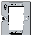
Accessories provided with the AP
|
|
|
M3.5 × 25 screw | M2.9 × 4 security screw | Mounting bracket |

Installation tools and equipment
When installing the AP, you might need the following tools. Prepare these tools and equipment yourself.
|
|
|
Phillips screwdriver | Needle-nose pliers | Wire-stripping pliers |
|
|
|
Torx screwdriver | Wire crimper |
|
Installing the AP
Figure 1 Installation flowchart
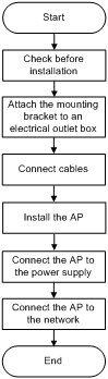
Check before installation
Before installing an AP, perform the following tasks:
· Connect the AP to the power supply and the network. Examine the LEDs to verify that the AP can operate correctly. For more information about AP LEDs, see "Appendix B LEDs and ports."
· Record the AP MAC address and serial number marked on the rear of the AP for future use.
Installing the AP
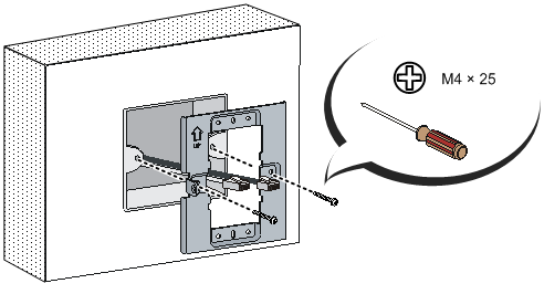
Attaching the mounting bracket to an electrical outlet box
As shown in Figure 2, use the M4 screws to attach the mounting bracket to an electrical outlet box.
Figure 2 Attaching the mounting bracket to an electrical outlet box
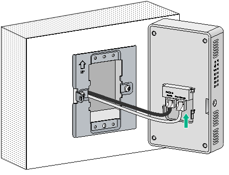
Connecting cables
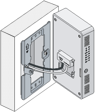
Connect the network cable from the box to the Uplink/PoE In port on the rear of the AP. Connect a cable to the Pass Through port on the rear of the AP as required.
| NOTE: The Pass Through ports on the rear and right side of the AP are standard RJ-45 ports. You can connect telephone cables or other cables to them as needed. |
Figure 3 Connecting cables
Installing the AP
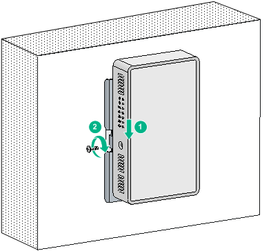
1. Align the installation hole in the rear of the AP with the standout on the mounting bracket.
Figure 4 Aligning the AP installation hole with the mounting bracket standout
2. Push the AP onto the mounting bracket, and then slide it down until it is fully engaged. Then secure the AP to the bracket by using the M2.9 × 4 security screw, as shown in Figure 5.
Figure 5 Securing the AP on the mounting bracket
Connecting the AP to the power supply
You can power the AP with local power or by using 802.3af- or 802.3at-compliant PoE.
Check before power-on
Check the following items before powering on the AP:
· To power the AP with local power, make sure the local power supply is reliably grounded.
· To power the AP through PoE, make sure the PoE power supply (PSE) is reliably grounded.
· To power the AP through PoE injector, make sure the PoE power supply (PSE) is reliably grounded.
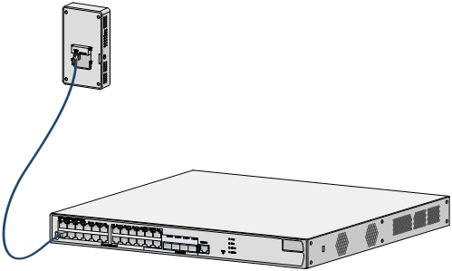
Connecting the PoE power supply
Use a network cable to connect the Uplink/PoE In port on the AP to a switch that supports PoE.
Figure 6 Connecting the PoE power supply
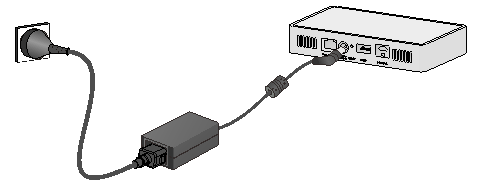
Connecting the local power supply
| NOTE: The Power adapter must be ordered separately. |
Table 1 Power adapter specifications
Item | Specification |
Input | 100 VAC to 240 VAC |
Output | +54 VDC |
You can power the AP by using an power adapter. Use the power adapter to connect the power port of the AP to the local power source.
Figure 7 Connecting the local power supply
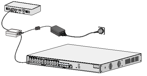
PoE injector power supply
| CAUTION: A PoE injector must be used together with an LPS-compliant adapter provided by H3C. |
The PoE injector must be ordered separately.
Connect the PoE injector to the AP and a switch with Ethernet cable. Use the power adapter to connect the power port of the PoE injector to the local power source.
Connect the PoE injector as shown inFigure 8
Figure 8 PoE injector power supply
Check after power-on
Verify that the AP is powered on and operating correctly by examining the AP status LED. For more information about AP LEDs, see "Appendix B LEDs and ports."
Connecting the AP to the network
For Internet or MAN access, connect an Ethernet port on the AP to an Ethernet port on an Ethernet switch, and then verify that the AP has been connected to the network.
The AP can only act as a fit AP, and all fit AP settings are configured on the AC. Execute the display wlan ap all command on the AC that connects to the fit AP. If the AP status is R/M, the AP is connected to the network.
Total number of APs: 1
Total number of connected APs: 1
Total number of connected manual APs: 1
Total number of connected common APs: 0
Total number of connected WTUs: 0
Total number of inside APs: 0
Maximum supported APs: 3072
Remaining APs: 3071
Total AP licenses: 128
Local AP licenses: 128
Server AP licenses: 0
Remaining local AP licenses: 127
Sync AP licenses: 0
AP information
State : I = Idle, J = Join, JA = JoinAck, IL = ImageLoad
C = Config, DC = DataCheck, R = Run, M = Master, B = Backup
AP name AP ID State Model Serial ID
ap1 1 R/M WA510H 219801A1NS8182032235
Appendix A Technical specifications
Item | Specification |
Protocol | IEEE802.11a/b/g/n/ac Wave2 |
Radio | Two |
Dimensions (H × W × D) | 150 × 86 × 36.8 mm (5.91 × 3.39 × 1.45 in) |
Weight | 250 g (0.55 lb) |
Built-in antenna | · 2.4 G antenna: 3.46 dBi peak gain · 5 G antenna: 3.40 dBi peak gain |
Maximum power consumption | 12.95 W |
Appendix B LEDs and ports
LEDs
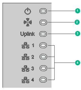
(1) Power LED | (2) Radio LED |
(3) Uplink LED | (4) Ethernet port LEDs |
Table 3 LED description
Mark | Status | Description |
Power LED | Off | The AP is not powered on. |
Steady yellow | An exception has occurred during AP initialization. | |
Flashing yellow (1 Hz) | No radio card is detected. | |
Flashing yellow (2 Hz) | The Ethernet interfaces are shut down and no mesh link is present. | |
Flashing green (0.5 Hz) | The AP has started up but is not connected to any AC. | |
Flashing green (2 Hz) | The AP is updating applications. | |
Steady green | The AP is operating correctly. | |
Radio LED | Off | No clients are associated with the AP or the LED is disabled from the CLI. |
Flashing green (1 Hz) | The 2.4 G radio has associated clients. | |
Flashing yellow (1 Hz) | The 5 G radio has associated clients. | |
Alternating green and yellow (1 Hz) | Both the 2.4 G and 5 G radios have associated clients. | |
Uplink LED | Off | No link is present on the port. |
Steady yellow | The negotiated rate is 10/100 Mbps. | |
Flashing yellow | The uplink port is sending or receiving data at 10/100 Mbps. | |
Steady green | The negotiated rate is 1000 Mbps. | |
Flashing green | The uplink port is sending or receiving data at 1000 Mbps. | |
Ethernet port LED | Off | No link is present on the port. |
Steady yellow | The negotiated rate is 10/100 Mbps. | |
Flashing yellow | The Ethernet port is sending or receiving data at 10/100 Mbps. | |
Steady green | The negotiated rate is 1000 Mbps. | |
Flashing green | The Ethernet port is sending or receiving data at 1000 Mbps. |
Ports
The AP provides the following ports:
· One console port.
· Four 10/100/1000 Mbps copper Ethernet ports.
· One power port.
· Two Pass Through ports.
· One Uplink/PoE In port.
· One USB port.
| NOTE: The AP also has a reset button. |
Figure 10 Bottom view
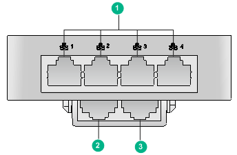
(1) 10/100/1000 Mbps copper Ethernet port | (2) Uplink/PoE In port |
(3) Pass Through port |
|
Figure 11 Right side view
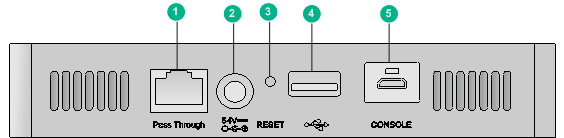
(1) Pass Through port | (2) Power port |
(3) Reset button | (4) USB port |
(5) Console port |
|
Table 4 Port description
Port | Standards and protocols | Description |
CONSOLE | RS/EIA-232 | The console port is used for configuration and management. NOTE: Only the maintenance staff can use the console port. |
ETH | · IEEE802.3 · IEEE802.3u · IEEE802.3af | The 10/100/1000 Mbps copper Ethernet port acts as a downlink interface. Ports 1 through 4 are represented by GE1/0/2 through GE1/0/5, respectively. |
Uplink/PoE In | · IEEE802.3 · IEEE802.3u · IEEE802.3af | The 10/100/1000 Mbps copper Ethernet port can act as an uplink interface connecting to Internet or MAN and receive PoE power supply at the same time. It is represented by interface GE1/0/1. |
DC 54V | N/A | The port receives +54 VDC power from the local supply. |
Pass Through | · IEEE802.3 · IEEE802.3u | The port is used for telephone cable or RJ-45 cable connection. |
USB | USB2.0 | The port is used for data reading and writing and charging. |
