- Table of Contents
- Related Documents
-
| Title | Size | Download |
|---|---|---|
| 01-Text | 1.86 MB |
Contents
Examining the installation site
Temperature and humidity requirements
Grounding and lightning protection
Installation tools and equipment
Connecting the grounding cable
Installing the outdoor antennas
Installing a directional antenna on a pole
Installing the omnidirectional antennas on poles
Connecting the AP to the power supply
Verifying the network connection
Verifying network connection for the fit AP
Verifying network connection for the fat AP
Logging in through the console port
Setting up the configuration environment
Logging in through the console port
Logging in through Telnet or Web
Product overview
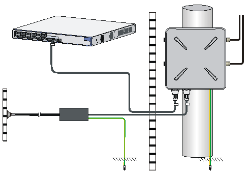
An H3C WA4320X AP can act as a fit AP to cooperate with wireless switches or access controllers to provide wireless access for WLAN users. The network settings are configured on the wireless switches or access controllers. The WA4320X can also act as a fat AP to provide wireless access for WLAN users.
Figure 1 Deployment of WA4320X APs (in fit AP mode)
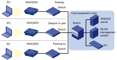
Figure 2 Deployment of WA4320X APs (in fat AP mode)
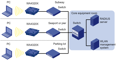
Table 1 H3C WA4320X specifications
|
Item |
Specification |
|
Dimensions (H × W × D) |
86.5 × 245 × 245 mm (3.41 × 9.65 × 9.65 in) |
|
Weight |
2 kg (4.41 lb) |
|
Power consumption |
8 W (standby) to 36 W (maximum) |
|
Protocols and materials |
· IEEE802.11a/b/g/n/ac · Waterproof cast aluminum + plastic housing |
Preparing for installation
|
|
WARNING! Install or remove the AP under the guidance of technical engineers and read this chapter before installation and operation. |
Examining the installation site
Before installation, examine the installation site to make sure the AP will work in a good environment.
Installation site selection
In engineering design, the site must be selected according to the network planning and technical requirements of the communications equipment, and the considerations such as climate, hydrology, geology, earthquake, electric power, and transportation.
Keep the AP away from high temperature, dust, harmful gases, inflammables, explosive substances, electromagnetic interference sources (heavy-duty radars, radio stations, or electrical substations), unstable voltage, heavy vibration, or loud noise. The installation site must be dry, without any leakage, dripping, or dew.
Temperature and humidity requirements
|
Specification |
|
|
Operating temperature |
–40°C to +65°C (–40°F to +149°F) |
|
Storage temperature |
–40°C to +85°C (–40°F to +185°F) |
|
Operating humidity (noncondensing) |
|
|
Storage humidity (noncondensing) |
0% to 100% |
Power supply
The AP can be powered by a power injector.
You can use an H3C PoE power injector to power the AP. For more information about powering the AP through the power injector, see "Connecting the AP to the ."
|
|
NOTE: No power injector is shipped with the AP. You need to order one separately. |
Grounding and lightning protection
The AP must be reliably grounded. Make sure the grounding conductors are separate and treated with corrosion protection.
Table 2 Grounding and lightning protection requirements
|
Item |
Requirements |
|
Grounding resistance |
· The grounding resistance is usually required to be less than 5 ohms, and less than 10 ohms in an area with less than 20 thunderstorm days a year. If a piece of angle steel is buried as the grounding conductor, the grounding resistance is required to be less than 10 ohms. In an area with a higher grounding resistance, reduce the grounding resistance by using brine or resistance reducing agent around the grounding conductor. · The top of the grounding conductor must be a minimum of 0.7 m (2.30 ft) away from the ground surface. In cold areas, the grounding conductor must be buried below the frozen soil layer. |
|
Grounding conductor |
· If a grounding strip is available, connect the yellow and green grounding cable of the AP to the grounding strip. To make a grounding cable, make sure the cable is with a cross-section area of a minimum of 6 mm2 (0.01 in2) and a length of no longer than 3 m (9.84 ft). · If no grounding strip is available, bury a piece of angle steel/steel tube a minimum of 0.5 m (1.64 ft) long in the earth to act as the grounding conductor. In the case of a piece of angle steel, the size must be a minimum of 50 × 50 × 5 mm (1.97. × 1.97 × 0.20 in); in the case of a piece of steel tube, it must be zinc-plated and have a wall thickness of a minimum of 3.5 mm (0.14 in). Weld the yellow and green grounding cable of the AP onto the grounding conductor and use anti-erosion treatment on the welding joint. With a cross-section area of a minimum of 6 mm2 (0.01 in2), the grounding cable must be as short as possible and must not be coiled. · Make sure that the grounding terminals of all the lightning arresters of the AP and the peer device of the AP are reliably grounded. |
|
Grounding lead-in |
A grounding lead-in is a metal conductor connecting a grounding net and a grounding strip. The grounding cable of the AP must be connected to the grounding strip. The grounding lead-in must be 30 m (98.43 ft) or shorter. A piece of zinc-coated flat steel with a cross-section area of 40 × 4 mm (1.57 × 0.16 in) or 50 × 5 mm (1.97 × 0.20 in) is recommended. Connect the grounding strip and the grounding lead-in of the AP through the yellow and green grounding cable with an area of 35 mm2 (0.05 in2), or weld them directly. Use anti-erosion treatment on the welding joint. |
|
Power grounding (AC) |
· Use a power cord with a protective earth (PE). Do not use a power cord with only an L line and an N line. · The neutral line of the power cord must not be connected with the PGND of other communications equipment. The L and N lines cannot be connected. |
|
Lightning rod |
· The lightning protection grounding (for example, the grounding of the lightning rod) must be connected to the grounding conductor of the equipment room. · The lightning rod must be tall enough to protect the AP and its antennas. · In plain areas, the shielding angle of the lightning rod must be less than 45 degrees. In mountainous areas or lightning areas, the shielding angle must be less than 30 degrees. |
|
Outdoor antenna |
The antenna support is already prepared according to the design requirements. |
|
Network cable |
· Use a shielded twisted pair cable for outdoor installation. Make sure that the devices at the two ends of the cable are reliably grounded. · If a metal tube is used, make sure the network cable is reliably grounded at both ends of the tube. |
Installation accessories
Table 3 Accessories provided with the AP
|
|
|
|
|
|
Liquid tight adapter and sealing nut |
Sealing plug |
Console cable (for fat AP only) |
Grounding cable |
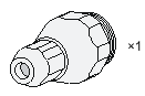
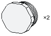
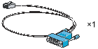
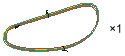
Table 4 Accessories not provided with the AP
|
|
|
|
|
|
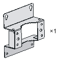
Mounting bracket |
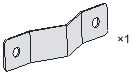
Pole fixed plate |
Long bolt/flat washer/spring washer/nut |
M6 x 12 screw |
|
|
|
|
|
|
Expansion screw |
|
|
|
Installation tools and equipment
When installing the AP, you may need the following tools. Prepare these tools and equipment yourself.
|
|
|
|
|
|
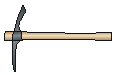
Pickaxe |
Shovel |
Adjustable wrench |
Wire clippers |
|
|
|
|
|
|
Crystal head crimping pliers |
Wire-stripping pliers |
Crimping pliers |
Phillips screwdriver |
|
|
|
|
|
|
Waterproof sealing tape |
Fiber fusion splicer |
Ladder |
|


Installing the AP
|
IMPORTANT: · The AP is typically installed on a high position. As a best practice, log in to and configure the AP before the installation. For more information about logging in to the AP, see "Logging in to the AP." · To ensure the radio coverage, have the AP installed by professionals as a best practice. |
Check before installation
Before installing an AP, perform the following tasks:
· Connect the AP to the power supply and the network. Examine the LEDs to verify that the AP can operate correctly. For more information about AP LEDs, see "Appendix A LEDs and ports."
· Verify that cabling on the installation site has been completed.
· Record the AP MAC address and serial number marked on the rear of the AP for future use.
When you install the AP, follow these restrictions and guidelines:
· If you install the AP on a pole, make sure the pole is vertical to the ground and has been treated with corrosion protection.
· Make sure the installation height and position meet the design requirements.
· If you pole-mount the AP on a rooftop, make sure the pole does not project from the wall of the building and the AP does not suspend in midair.
· To avoid high temperature caused by exposure to the sun, install the AP in a place without or with less direct sunlight and use protection methods if necessary.
· Install the AP with the Ethernet copper and fiber ports facing down and route the cables downward.
Installing the AP
Mounting the AP on a pole
|
|
CAUTION: To install the AP and antennas on the same pole, the outer diameter of the pole must be between 60 mm and 70 mm (2.36 in and 2.76 in). |
Pole mounting is suitable for rooftop installation.
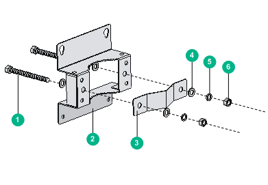
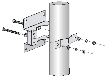
The AP can be fixed to a pole whose outer diameter is between 60 mm and 110 mm (2.36 in and 4.33 in) by using a mounting kit. The mounting kit includes a mounting bracket and a pole fixed plate as shown in Figure 3.
|
(1) Long bolt |
(2) Mounting bracket |
(3) Pole fixed plate |
|
(4) Flat washer |
(5) Spring washer |
(6) Nut |
To install the AP on a pole:
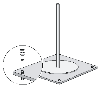
1. Vertically fix the pedestal of the pole to the rooftop or a cement pier on the rooftop with expansion screws.
Figure 4 Pole and pedestal
2. Fix the mounting bracket to the pole.
Figure 5 Fixing the mounting bracket to the pole
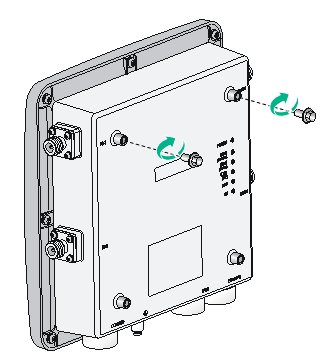
3. Install two M6 × 12 screws into the two upper screw holes on the AP rear. Do not fasten the screws all the way in.
Figure 6 Installing two screws into the two upper screw holes
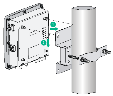
4. Insert the two M6 × 12 screws through the mounting holes on the mounting bracket and press the AP downward to fix the AP onto the mounting bracket.
Figure 7 Fixing the AP onto the mounting bracket (1)
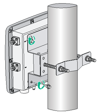
5. Insert the other two M6 × 12 screws through the two lower mounting holes and fasten the four screws tightly.
Figure 8 Fixing the AP onto the mounting bracket (2)
Mounting the AP on a wall
No expansion screws are provided with the AP. Prepare four sets of 6 × 60 or 6 × 80 expansion screws, flat washer, spring washer, and nut yourself.
To install the AP on a wall:
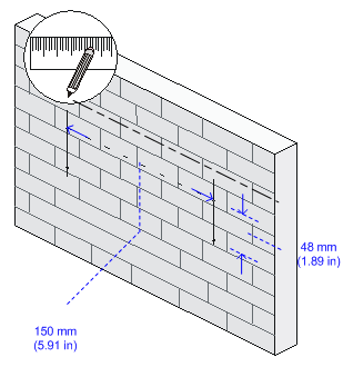
1. Mark the installation holes on the wall by using the mounting bracket, as shown in Figure 9.
Figure 9 Marking the installation holes on the wall
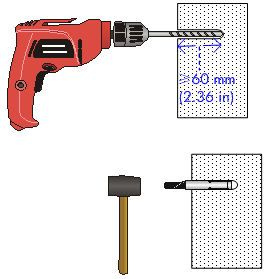
2. Drill holes with a diameter of 8 mm (0.31 in) and a minimum depth of 60 mm (2.36 in) in the marked positions. Insert an expansion screw into each hole, and tap the expansion screw with a rubber hammer until it is all flush with the wall surface, as shown in Figure 10.
When you drill holes, follow these restrictions and guidelines:
¡ Hold the drill handle with both hands, with the bit vertical to the wall surface, and prevent wall damage or tilted holes.
¡ If the wall surface is too solid and slippery to locate the bit, punch a notch first.
¡ Each hole must have the same depth.
Figure 10 Installing expansion screws in the wall
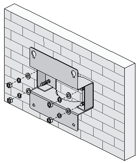
3. Attach the mounting bracket to the wall, as shown in Figure 11.
Figure 11 Attaching the mounting bracket to the wall
4. Install two M6 × 12 screws into the two upper screw holes on the AP rear. Do not fasten the screws all the way in.
5. Insert the two screws through the mounting holes on the mounting bracket and press the AP downward to fix the AP onto the mounting bracket.
Figure 12 Attaching the AP to the mounting bracket
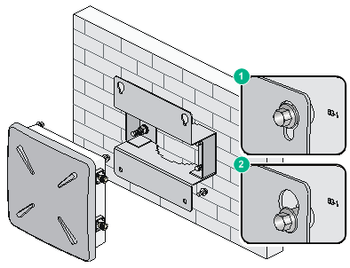
6. Insert the other two M6 × 12 screws through the two lower mounting holes and fasten the four screws tightly.
Connecting the grounding cable
Connect the grounding terminal of the AP to the grounding point with the yellow and green grounding cable shipped with the AP. For more information, see "Grounding and lightning protection."
|
|
NOTE: The grounding terminal of the power injector must also be grounded. |
Installing the outdoor antennas
Outdoor antennas include directional and omnidirectional antennas. The following section describes how to install directional and omnidirectional antennas.
When you install the outdoor antennas, follow these restrictions and guidelines:
· Keep the AP far from high-power electronic equipment and make sure there are no large obstacles and metal objects in the wireless coverage.
· Make sure the antenna mounting bracket is stably mounted on the pole that is vertical to the ground. Use oxidation-resistant metal materials.
· Fix the pedestal of the antenna pole to a cement pier or add weight to the pole. Do not install the antenna pole or antenna support directly on the waterproof layer of the rooftop.
· Make sure the omnidirectional antenna is vertical to the ground.
· Make sure the antenna cable is firmly connected to the antenna.
· Make sure the antenna cable connection is sealed with waterproof sealing tape.
Installing a directional antenna on a pole
Make sure that the location of the pole does not hamper the adjustment of antenna direction and tilt.
Do not install two directional antennas back to back. To install two directional antennas on the same pole, make sure the distance between the antennas is larger than 4 m (13.12 ft).
To install a directional antenna on a pole:
1. Weld the lightning rod to the top of the pole.
2. Install the pole on a parapet or cement pier.
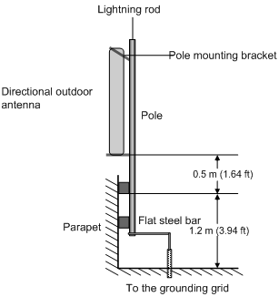
¡ If there are parapets on the rooftop and the height of the parapets is no less than 1.2 m (3.94 ft), you can fix the pole on a parapet with expansion screws and fix the directional antenna on the pole with the pole mounting bracket. See Figure 13.
Figure 13 Installing a directional antenna on a parapet (1)
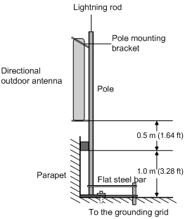
¡ If there are parapets on the rooftop and the height of the parapets is less than 1.2 m (3.94 ft), you can fix the pole on a parapet at one point with expansion screws and fix the bottom end of the pole to the rooftop surface, and then fix the directional antenna on the pole with the pole mounting bracket. See Figure 14.
Figure 14 Installing a directional antenna on a parapet (2)
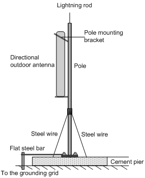
¡ If there is no parapet on the rooftop, fix the pole to the rooftop surface or a cement pier on the rooftop with expansion screws and stabilize the pole with steel wires. Then, install the directional antenna on the pole, as shown in Figure 15.
Figure 15 Installing a directional antenna on a parapet (3)
3. Connect the pole to a grounding grid with a flat steel bar (40 x 4 mm or 1.57 x 0.16 in).
4. Fix the antenna on the pole with the pole mounting bracket.
Installing the omnidirectional antennas on poles
|
|
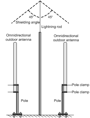
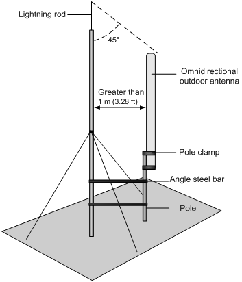
CAUTION: · The diameter of the poles for omnidirectional antennas must be 50 mm to 70 mm (1.97 in to 2.76 in). Typically, poles are made of round steel bars 50 mm (1.97 in) in diameter. · The pole clamp at the top of the pole and the one at the bottom of the antenna must be level, as shown in Figure 16. · The antennas must be installed high enough to provide the desired coverage and the antenna tops must remain within the shielding angle (45°) of the lightning rod. |
Omnidirectional antennas must be kept a minimum of one meter (3.28 ft) away horizontally from metal objects.
Therefore, do not weld the lightning rod on a pole attached with an antenna. Install the lightning rod on a separate pole between the two omnidirectional antennas and ensure that the antennas are within the shielding angle of the lightning rod.
Figure 16 Installing omnidirectional antennas
If separately installing the lightning rod is not practical, use the alternative method shown in Figure 17. Allow a minimum of one meter (3.28 ft) of clearance between the lightning rod and the antenna.
Figure 17 Alternative method for installing an omnidirectional antenna
|
|
NOTE: In Figure 17, the antenna pole is not fixed on the cement pier. Instead, the antenna pole is fixed by welding two angle steel bars between the antenna pole and the lightning rod pole. |
Connecting cables
This section describes how to connect the antenna cable, Ethernet cable, fiber cable, and power cord.
When you connect cables, follow these restrictions and guidelines:
· Lay cables according to the engineering design. Do not cross or twist cables, and make sure the cables do not have any cracks and are not broken.
· To avoid high-current and high-electromagnetic interference, do not place the cables together with heavy-current pipelines, fire mains, or building lightning rods.
· As a best practice, use PVC, iron, or Plica tubes, or wire casings connected by flexible pipes or joints for cable deployment. Place the tubes or casings against the wall and use cable ties, hangers, or angle steel bars to fix them with a separation distance of 1 to 1.5 m (3.28 to 4.92 ft). If a metal tube is used, make sure the cable is reliably grounded at both ends of the tube.
· As a best practice, drill a hole at the bottom of outdoor horizontal PVC tubes every 6 m (19.69 ft) for water draining.
· Holes through a wall must be sealed with waterproof and flame-resistant materials.
Connecting the antenna cables
The antenna cables connect the antenna ports (2.4 GHz and 5 GHz) to the outdoor antennas.
To connect the antenna cables:
1. Connect the antenna cables to the antenna ports of the AP at one end and to the outdoor antennas at the other end.
Connect the cables to the 2.4 G-1/2 and 5G-1/2 antenna ports on the AP.
Figure 18 Connecting the antenna cables to the AP antenna ports
2. Wrap the connections with insulating tape and apply several layers of waterproof sealing tape over the insulating tape.
|
|
NOTE: · When connecting the antenna cable to an AP, antenna, coupler, or power divider, make sure the cable remains straight for a minimum of 5 cm (1.97 in) out of the connector. · Prepare an antenna arrestor yourself if required. · Make sure that the grounding cables are reliably grounded during outdoor deployment. · You can order the standard ready-made antenna cables, or order cables of desired lengths and N-type antenna connectors and make antenna cables on-site as needed. · Test the Voltage Standing Wave Ratio (VSWR) of the antenna connectors and cables made on-site. The cable reflectivity on the working channel must meet the requirements of the AP and the engineering design. · Stretch the waterproof sealing tape till the width of the tape is reduced to 3/4 of the original width and wrap the waterproof sealing tape around the cable to achieve desired waterproof performance. |
Connecting the fiber cable
|
|
CAUTION: · To avoid AP damage, follow the procedure when connecting the fiber cable. · When a fiber cable is used to transmit data, both ends of the cable must use appropriate SFP transceiver modules. The SFP transceiver modules provided by H3C meet the outdoor deployment requirements, use single mode fiber, and have a transmission distance of 15 km (9.32 mi). |
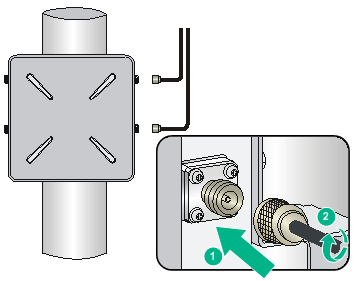
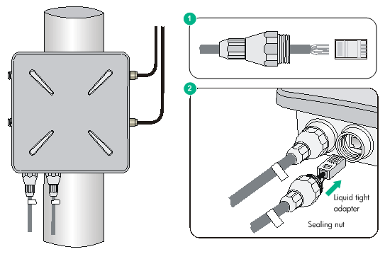
If the AP is connected to the switch through a fiber cable, an SFP transceiver module and a liquid tight adapter are required at the AP side. See Figure 19.
Figure 19 Connecting the fiber cable to the fiber port of the AP
To connect a fiber cable:
1. Insert an SFP transceiver module into the fiber port of the AP.
2. Insert an LC fiber connector with liquid tight adapter to the SFP transceiver module.
3. Loosen the sealing nut, tighten the liquid tight adapter, and then tighten the sealing nut.
4. Seal the connection with waterproof sealing tape.
|
|
NOTE: · The optional fiber cable is a 10-meter pigtail with waterproof sheath. One end of the pigtail uses an LC connector and a liquid tight adapter and is inserted into the fiber port of the AP and the other end uses an SC connector and is connected to an end user terminal or switch. · If the fiber is connected to a fiber termination box, connect the SC connector to a pair of SC sockets. The one marked as A is the receiving port (RX) of the AP and must be connected to the transmitting port (TX) of the peer device; the one marked as B is the TX port of the AP and must be connected to the RX port of the peer device. Typically, fiber termination boxes are not waterproof. Put the fiber termination box indoor or in a waterproof cabinet. · If the fiber is connected to a fiber connector box, cut off the SC connector and splice the fiber end with the connector on the connector box. The pigtail marked as A is connected to the RX port of the AP and the TX port of the peer device; the pigtail marked as B is connected to the TX port of the AP and the RX port of the peer device. Fiber connector boxes are usually waterproof and can be buried underground or mounted on a pole. |
Connecting the Ethernet cable
|
|
CAUTION: · To avoid AP damage, follow the procedure when connecting the Ethernet cable. · Use a shielded twisted pair cable (category 5e or higher) with waterproof sheath for outdoor installation. The cable length from the Ethernet switch to the AP cannot exceed 100 m (328.08 ft). |
To connect the Ethernet cable:
1. Route the Ethernet cable with waterproof sheath from the equipment room to the AP.
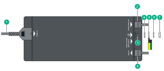
Figure 20 Connecting a copper cable
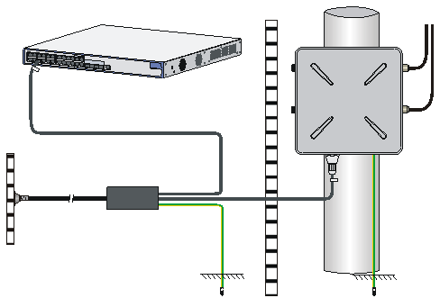
Figure 21 Connecting a fiber cable
|
(2) Data and power output cable |
(3) Grounding terminal |
|
|
(4) Flat washer |
(5) Grounding cable with ring terminal |
(6) Spring washer |
|
(7) Nut |
(8) Data input cable |
|
Table 5 Power injector specifications
|
Item |
Description |
|
Input |
100 VAC to 240 VAC at 1.5 A; 50/60 Hz |
|
Output |
52 V |
|
Discharge current |
3 kA 8/20 μs |
|
|
IMPORTANT: · If the fiber port acts as the uplink port, the copper port can only provide PoE services and does not transmit data. · The Ethernet port marked with "Signal & power output" on the power injector must be connected to copper port on the AP. |
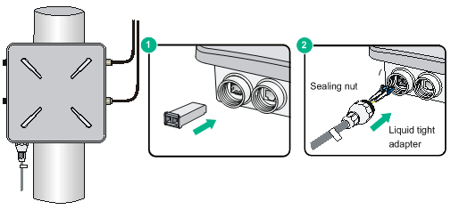
2. Insert the copper cable through the liquid tight adapter and crimp an RJ-45 connector on the end of the cable. For more information about crimping an RJ-45 connector on a cable, see "Appendix B Crimping an RJ-45 connector."
3. Connect the cable to the copper port of the AP.
Figure 23 Connecting the copper cable to the copper port of the AP
4. Loosen the sealing nut, tighten the liquid tight adapter, and then tighten the sealing nut.
5. Seal the connection with waterproof sealing tape.
Connecting the AP to the power supply
|
|
CAUTION: · Make sure the installation of the AP is complete before powering on the AP. · Make sure the power injector is well fixed and has good ventilation and heat dissipation performance. · If multiple power injectors are installed in the same equipment room or low voltage silo, use a power strip connected to the backup air switch of the AC box to power the injectors. |
|
|
NOTE: Put the power injector at the switch side, and the switch connected to the power injector does not need to be PoE+ capable. |
The AP can be powered by a power injector.
To connect the power injector to the AP as shown in Figure 22:
1. Connect the power input line to an AC power supply.
2. Connect the signal & power output line to the copper port of the AP.
3. Connect the signal input line to a switch or an access controller.
4. Ground the grounding terminal of the power injector.
Labeling cables
After cable connecting, paste labels on each cable as a best practice for future maintenance:
· Paste a label to both ends of a cable and every certain distance.
· Use coiled or flag-type labels for antenna and Ethernet cables. Use flag-type labels for fiber cables.
· Use waterproof labels with clear content. Paste labels to proper places where they can be seen directly.
· Use transparent waterproof tape to seal outdoor labels.
Verifying the installation
After the installation and cabling, check the following items before powering on the AP:
· The power supply meets the power specification of the AP.
· The AP is reliably grounded.
· The Ethernet cables are correctly connected.
· The outdoor antennas are installed.
· The cables are correctly labeled.
· The unused ports on the AP are sealed with waterproof plugs.
Powering on the AP
Make sure that all the cables are correctly connected. Then, switch on the external power supply and check the power LED of the AP. For more information about LEDs, see "Appendix A LEDs and ports."
Verifying the network connection
Verifying network connection for the fit AP
All settings of the fit AP are configured on the AC. Use the display wlan ap all command on the AC that connects to the fit AP. If the AP status is R/M, the AP is connected to the network.
Total number of APs: 1
Total number of connected APs: 1
Total number of connected manual APs: 1
Total number of connected auto APs: 0
Total number of connected common APs: 1
Total number of connected WTUs: 0
Total number of inside APs: 0
Maximum supported APs: 3072
Remaining APs: 3070
Total AP licenses: 128
Remaining AP licenses: 127
AP information
State : I = Idle, J = Join, JA = JoinAck, IL = ImageLoad
C = Config, DC = DataCheck, R = Run M = Master, B = Backup
AP name APID State Model Serial ID
ap1 1 R WA4320X 219801A0REM153000023
Verifying network connection for the fat AP
Use the ping command on the fat AP to ping the uplink network device. If the ping operation succeeds, the AP is connected to the network successfully.
Logging in to the AP
|
|
IMPORTANT: The AP is typically installed on a high position. As a best practice, log in to and configure the AP before the installation. |
This section applies only when the AP acts as a fat AP. When the AP acts as a fat AP, you can log in to the AP through the console port, or through Telnet or Web to configure it. Login through the console port is the prerequisite to configuring other login methods. Before you log in to the fat AP through Telnet or Web, obtain the IP address of the AP first.
Logging in through the console port
Prepare the following items before logging in through the console port:
· An 8-core console cable, with a crimped RJ-45 connector at one end, and a DB-9 connector at the other end.
· A configuration terminal with a serial port, such as a laptop or PC.
Setting up the configuration environment
|
|
CAUTION: The serial ports on PCs do not support hot swapping. To connect a PC to an operating device, first connect the PC end. To disconnect a PC from an operating device, first disconnect the device end. |
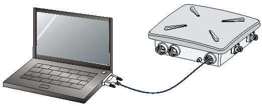
Connecting the console cable
1. Connect the DB-9 connector to the serial port of the PC.
2. Connect the RJ-45 connector to the console port of the AP.
Figure 24 Connecting the console cable
Logging in through the console port
Power on the AP, and you can see the following information:
System is starting...
Booting Normal Extend BootWare.
……
System application is starting...
Startup configuration file does not exist.
User interface con0 is available.
Press ENTER to get started.
Logging in through Telnet or Web
By default, Telnet login and Web login are enabled. You can log in to the AP by using the following default login information:
· Username—admin.
· Password—h3capadmin.
· IP address of VLAN-interface 1 of the AP—192.168.0.50 with subnet mask 255.255.255.0.
If the default IP address is changed, perform either of the following tasks:
¡ Contact the administrator to get the new IP address.
¡ Log in to the AP from the console port and execute the display vlan 1 command to view the IP address.
|
|
NOTE: For more information about login through Telnet or Web, see fundamental configuration in H3C WA4320X Access Controllers Configuration Guides. |