- Table of Contents
-
- 05-Layer 3 - IP Services Configuration Guide
- 00-Preface
- 01-ARP configuration
- 02-IP addressing configuration
- 03-DHCP configuration
- 04-DNS configuration
- 05-IP forwarding basics configuration
- 06-Fast forwarding configuration
- 07-Adjacency table configuration
- 08-IRDP configuration
- 09-IP performance optimization configuration
- 10-UDP Helper configuration
- 11-IPv6 basics configuration
- 12-DHCPv6 configuration
- 13-IPv6 fast forwarding configuration
- 14-Tunneling configuration
- 15-GRE configuration
- 16-HTTP redirect configuration
- Related Documents
-
| Title | Size | Download |
|---|---|---|
| 14-Tunneling configuration | 355.07 KB |
Feature and hardware compatibility
Configuring a tunnel interface
Displaying and maintaining tunneling configuration
Troubleshooting tunneling configuration
IPv6 over IPv4 tunneling configuration task list
Configuring an IPv6 over IPv4 manual tunnel
6to4 tunnel configuration example
6to4 relay configuration example
Configuring an IPv4 over IPv4 tunnel
Configuring an IPv4 over IPv6 manual tunnel
Configuring an IPv6 over IPv6 tunnel
Configuring tunneling
Overview
Tunneling encapsulates the packets of a network protocol within the packets of a second network protocol and transfers them over a virtual point-to-point connection. The virtual connection is called a tunnel. Packets are encapsulated at the tunnel source and de-encapsulated at the tunnel destination.
Tunneling supports the following technologies:
· EVI tunneling.
· GRE tunneling.
· MPLS TE tunneling.
· VXLAN tunneling and VXLAN-DCI tunneling.
· IPv6 over IPv4 tunneling, IPv4 over IPv4 tunneling, and IPv4/IPv6 over IPv6 tunneling.
Feature and hardware compatibility
Tunneling is not supported on SA interface modules.
Configuring a tunnel interface
Configure a tunnel interface (Layer 3 virtual interface) at both ends of a tunnel. The devices use the tunnel interface to identify, process, and send packets for the tunnel.
Follow these guidelines when you configure a tunnel interface:
· The device cannot directly route a tunneled packet based on its destination address. The packet is sent to a tunnel-type service loopback group, which then delivers the packet to the forwarding module for Layer 3 forwarding. For the tunnel interface to forward and receive packets, you must configure a tunnel-type service loopback group on the device. For information about service loopback group, see Layer 2—LAN Switching Configuration Guide.
· When an active/standby switchover occurs or the standby MPU is removed, the tunnel interfaces configured on the active or standby MPU still exist. To delete a tunnel interface, use the undo interface tunnel command.
· Do not specify the same tunnel source and destination addresses for the tunnel interfaces on the same device.
To configure a tunnel interface:
|
Step |
Command |
Remarks |
|
1. Enter system view. |
system-view |
N/A |
|
2. Create a tunnel interface, specify the tunnel mode, and enter tunnel interface view. |
interface tunnel number [ mode { evi | gre [ ipv6 ] | ipv4-ipv4 | ipv6 | ipv6-ipv4 [ 6to4 | isatap ] | mpls-te | vxlan | vxlan-dci } ] |
By default, no tunnel interfaces exist. When you create a new tunnel interface, you must specify the tunnel mode. When you enter the view of an existing tunnel interface, you do not need to specify the tunnel mode. For packet tunneling to succeed, the two ends of a tunnel must use the same tunnel mode. |
|
3. Configure a source address or source interface for the tunnel interface. |
source { ipv4-address | ipv6-address | interface-type interface-number } |
By default, no source address or source interface is configured for the tunnel interface. If you specify a source address, it is used as the source address of tunneled packets. If you specify a source interface, the primary IP address of this interface is used as the source IP address of tunneled packets. |
|
4. Configure a destination address for the tunnel interface. |
destination { ipv4-address | ipv6-address | dhcp-alloc interface-type interface-number } |
By default, no destination address is configured for the tunnel interface. The tunnel destination address must be the IP address of the receiving interface on the tunnel peer. It is used as the destination IP address of tunneled packets. |
|
5. (Optional.) Configure a description for the interface. |
description text |
By default, the description for a tunnel interface is Tunnel number Interface. |
|
6. Set the MTU of the tunnel interface. |
mtu size |
If the tunnel interface has never been up, the default MTU is 64000 bytes. If the tunnel interface is up, the default MTU is identical to the outgoing interface's MTU minus the length of the tunnel headers. The outgoing interface is automatically obtained through routing table lookup based on the tunnel destination address. |
|
7. Set the expected bandwidth for the tunnel interface. |
bandwidth bandwidth-value |
The default expected bandwidth (in kbps) is the interface maximum rate divided by 1000. The expected bandwidth for the tunnel interface affects the link cost value. For more information, see Layer 3—IP Routing Configuration Guide. The VXLAN and VXLAN-DCI tunnel interfaces do not support this command. |
|
8. Set the ToS for tunneled packets. |
tunnel tos tos-value |
The default setting is the same as the ToS of the original packets. |
|
9. Set the TTL for tunneled packets. |
tunnel ttl ttl-value |
The default TTL for tunneled packets is 255. |
|
10. (Optional.) Restore the default settings of the tunnel interface. |
default |
N/A |
|
11. (Optional.) Shut down the tunnel interface. |
shutdown |
By default, a tunnel interface is up. |
Displaying and maintaining tunneling configuration
Execute display commands in any view and reset commands in user view.
|
Task |
Command |
Remarks |
|
Display information about tunnel interfaces. |
display interface [ tunnel [ number ] ] [ brief [ description | down ] ] |
N/A |
|
Display IPv6 information on tunnel interfaces. |
display ipv6 interface [ tunnel [ number ] ] [ brief ] |
For more information about this command, see IPv6 basics in Layer 3—IP Services Command Reference. |
|
Clear statistics on tunnel interfaces. |
reset counters interface [ tunnel [ number ] ] |
N/A |
|
Clear IPv6 statistics on tunnel interfaces. |
· In standalone mode: · In IRF mode: |
For more information about this command, see IPv6 basics in Layer 3—IP Services Command Reference. |
Troubleshooting tunneling configuration
Symptom
A tunnel interface configured with related parameters such as tunnel source address, tunnel destination address, and tunnel mode cannot come up.
Analysis
The physical interface of the tunnel does not come up, or the tunnel destination is unreachable.
Solution
1. To resolve the problem:
¡ Use the display interface or display ipv6 interface command to verify that the physical interface of the tunnel is up. If the physical interface is down, check the network connection.
¡ Use the display ipv6 routing-table or display ip routing-table command to verify that the tunnel destination is reachable. If the route is not available, configure a route to reach the tunnel destination.
2. If the problem persists, contact H3C Support.
IPv6 over IPv4 tunneling
Overview
Implementation
IPv6 over IPv4 tunneling enables isolated IPv6 networks to communicate, as shown in Figure 1.
|
|
NOTE: The devices at both ends of an IPv6 over IPv4 tunnel must support the IPv4/IPv6 dual stack. |
Figure 1 IPv6 over IPv4 tunnel
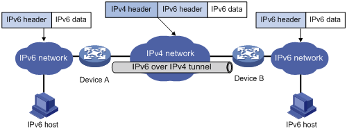
The IPv6 over IPv4 tunnel processes packets by using the following steps:
1. A host in the IPv6 network sends an IPv6 packet to Device A at the tunnel source.
2. After Device A receives the IPv6 packet, it processes the packet as follows:
a. Searches the routing table to identify the outgoing interface for the IPv6 packet.
The outgoing interface is the tunnel interface, so Device A knows that the packet needs to be forwarded through the tunnel.
b. Adds an IPv4 header to the IPv6 packet and forwards the packet through the physical interface of the tunnel.
In the IPv4 header, the source IPv4 address is the IPv4 address of the tunnel source, and the destination IPv4 address is the IPv4 address of the tunnel destination.
3. Upon receiving the packet, Device B de-encapsulates the packet.
4. If the destination address of the IPv6 packet is itself, Device B forwards it to the upper-layer protocol. If it is not, Device B forwards it according to the routing table.
Tunnel modes
IPv6 over IPv4 tunnels include manually configured tunnels and automatic tunnels, depending on how the IPv4 address of the tunnel destination is obtained.
· Manually configured tunnel—The destination IPv4 address of the tunnel cannot be automatically obtained from the destination IPv6 address of an IPv6 packet at the tunnel source. It must be manually configured.
· Automatic tunnel—The destination IPv4 address of the tunnel can be automatically obtained from the destination IPv6 address (with an IPv4 address embedded) of an IPv6 packet at the tunnel source.
The source IPv4 addresses for all IPv6 over IPv4 tunnels are manually configured.
According to the way an IPv6 packet is encapsulated, IPv6 over IPv4 tunnels are divided into the modes shown in the following table:
Table 1 Automatic tunnel modes and key parameters
|
Tunnel mode |
Destination IPv6 address format |
|
Manually configured tunnel |
|
|
IPv6 over IPv4 manual tunneling |
Ordinary IPv6 address. |
|
Automatic tunnel |
|
|
6to4 tunneling |
6to4 address. The address format is 2002:abcd:efgh:subnet number::interface ID/48. · 2002 is the fixed IPv6 address prefix. · abcd:efgh represents a 32-bit globally unique
IPv4 address in hexadecimal notation. · The subnet number identifies a subnet in the 6to4 network. · The subnet number::interface ID uniquely identifies a host in the 6to4 network. NOTE: The destination IPv4 address of a 6to4 tunnel is embedded in the destination 6to4 address. This mechanism enables the device to automatically obtain the tunnel destination address. |
|
ISATAP tunneling |
ISATAP address. The address format is prefix:0:5EFE:abcd:efgh/64. · The 64-bit prefix is a valid IPv6 unicast address prefix. · The abcd:efgh/64 segments represent a 32-bit IPv4 address, which identifies the tunnel destination but does not require global uniqueness. |
· IPv6 over IPv4 manual tunneling—A point-to-point link. This type of tunneling provides the following solutions:
¡ Connects isolated IPv6 networks over an IPv4 network.
¡ Connects an IPv6 network and an IPv4/IPv6 dual-stack host over an IPv4 network.
· 6to4 tunneling
¡ Ordinary 6to4 tunneling—A point-to-multipoint automatic tunnel. It is used to connect multiple isolated IPv6 networks over an IPv4 network.
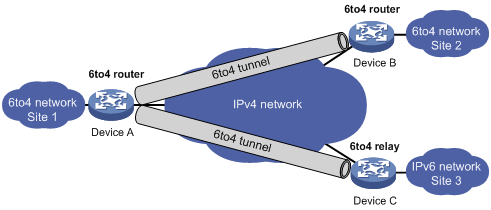
¡ 6to4 relay—Connects a 6to4 network and an IPv6 network that uses an IP prefix other than 2002::/16. A 6to4 relay router is a gateway that forwards packets from a 6to4 network to an IPv6 network.
As shown in Figure 2, 6to4 network Site 1 communicates with IPv6 network Site 3 over a 6to4 tunnel. Configure a static route on the border router (Device A) in the 6to4 network. The next hop address must be the 6to4 address of the 6to4 relay router (Device C). Device A forwards all packets destined for the IPv6 network over the 6to4 tunnel, and Device C then forwards them to the IPv6 network.
Figure 2 Principle of 6to4 tunneling and 6to4 relay
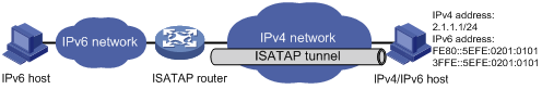
· ISATAP tunneling—A point-to-multipoint automatic tunnel. It provides a solution to connect an IPv6 host and an IPv6 network over an IPv4 network. ISATAP tunnels are mainly used for communication between IPv6 routers or between an IPv6 host and an IPv6 router over an IPv4 network.
Figure 3 Principle of ISATAP tunneling
IPv6 over IPv4 tunneling configuration task list
Perform one of the following tasks:
|
Tasks at a glance |
Configuring an IPv6 over IPv4 manual tunnel
Follow these guidelines when you configure an IPv6 over IPv4 manual tunnel:
· The tunnel destination address specified on the local device must be identical with the tunnel source address specified on the tunnel peer device.
· Do not specify the same tunnel source and destination addresses for the tunnel interfaces in the same mode on a device.
· To ensure correct packet forwarding, identify whether the destination IPv6 network and the IPv6 address of the local tunnel interface are on the same subnet. If they are not, configure a route reaching the destination IPv6 network through the tunnel interface. You can configure the route by using one of the following methods:
¡ Configure a static route, and specify the local tunnel interface as the egress interface or specify the IPv6 address of the peer tunnel interface as the next hop.
¡ Enable a dynamic routing protocol on both tunnel interfaces to achieve the same purpose.
For more information about route configuration, see Layer 3—IP Routing Configuration Guide.
To configure an IPv6 over IPv4 manual tunnel:
|
Step |
Command |
Remarks |
|
1. Enter system view. |
system-view |
N/A |
|
2. Enter IPv6 over IPv4 manual tunnel interface view. |
interface tunnel number [ mode ipv6-ipv4 ] |
N/A |
|
3. Specify an IPv6 address for the tunnel interface. |
See "Configuring basic IPv6 settings." |
By default, no IPv6 address is configured for the tunnel interface. |
|
4. Configure a source address or source interface for the tunnel interface. |
source { ipv4-address | interface-type interface-number } |
By default, no source address or source interface is configured for the tunnel interface. If you specify a source address, it is used as the source IP address of tunneled packets. If you specify a source interface, the primary IP address of this interface is used as the source IP address of tunneled packets. |
|
5. Configure a destination address for the tunnel interface. |
destination ipv4-address |
By default, no destination address is configured for the tunnel interface. The tunnel destination address must be the IP address of the receiving interface on the tunnel peer. It is used as the destination IP address of tunneled packets. |
|
6. (Optional.) Set the DF bit for tunneled packets. |
tunnel dfbit enable |
By default, the DF bit is not set for tunneled packets. |
|
7. Return to system view. |
quit |
N/A |
|
8. (Optional.) Enable dropping IPv6 packets that use IPv4-compatible IPv6 addresses. |
tunnel discard ipv4-compatible-packet |
By default, IPv6 packets that use IPv4-compatible IPv6 addresses are not dropped. |
Configuration example
Network requirements
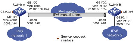
As shown in Figure 4, configure an IPv6 over IPv4 tunnel between Switch A and Switch B so the two IPv6 networks can reach each other over the IPv4 network. Because the tunnel destination IPv4 address cannot be automatically obtained from the destination IPv6 addresses, configure an IPv6 over IPv4 manual tunnel.
Configuration procedure
Make sure Switch A and Switch B have the corresponding VLAN interfaces created and can reach each other through IPv4.
· Configure Switch A:
# Add GigabitEthernet 1/0/2 (the physical interface of the tunnel) to VLAN 100.
<SwitchA> system-view
[SwitchA] vlan 100
[SwitchA-vlan100] port gigabitethernet 1/0/2
[SwitchA-vlan100] quit
# Specify an IPv4 address for VLAN-interface 100.
[SwitchA] interface vlan-interface 100
[SwitchA-Vlan-interface100] ip address 192.168.100.1 255.255.255.0
[SwitchA-Vlan-interface100] quit
# Add GigabitEthernet 1/0/1 to VLAN 101.
[SwitchA] vlan 101
[SwitchA-vlan101] port gigabitethernet 1/0/1
[SwitchA-vlan101] quit
# Specify an IPv6 address for VLAN-interface 101.
[SwitchA] interface vlan-interface 101
[SwitchA-Vlan-interface101] ipv6 address 3002::1 64
[SwitchA-Vlan-interface101] quit
# Create service loopback group 1, and specify its service type as tunnel.
[SwitchA] service-loopback group 1 type tunnel
# Add GigabitEthernet 1/0/3 to service loopback group 1.
[SwitchA] interface gigabitethernet 1/0/3
[SwitchA-GigabitEthernet1/0/3] port service-loopback group 1
[SwitchA-GigabitEthernet1/0/3] quit
# Create IPv6 over IPv4 manual tunnel interface Tunnel 1.
[SwitchA] interface tunnel 1 mode ipv6-ipv4
# Specify an IPv6 address for the tunnel interface.
[SwitchA-Tunnel1] ipv6 address 3001::1/64
# Specify VLAN-interface 100 as the source interface of the tunnel interface.
[SwitchA-Tunnel1] source vlan-interface 100
# Specify the destination address for the tunnel interface as the IP address of the VLAN-interface 100 on Switch B.
[SwitchA-Tunnel1] destination 192.168.50.1
[SwitchA-Tunnel1] quit
# Configure a static route destined for IPv6 network 2 through tunnel 1.
[SwitchA] ipv6 route-static 3003:: 64 tunnel 1
· Configure Switch B:
# Add GigabitEthernet 1/0/2 (the physical interface of the tunnel) to VLAN 100.
<SwitchB> system-view
[SwitchB] vlan 100
[SwitchB-vlan100] port gigabitethernet 1/0/2
[SwitchB-vlan100] quit
# Specify an IPv4 address for VLAN-interface 100.
[SwitchB] interface vlan-interface 100
[SwitchB-Vlan-interface100] ip address 192.168.50.1 255.255.255.0
[SwitchB-Vlan-interface100] quit
# Add GigabitEthernet 1/0/1 to VLAN 101.
[SwitchB] vlan 101
[SwitchB-vlan101] port gigabitethernet 1/0/1
[SwitchB-vlan101] quit
# Specify an IPv6 address for VLAN-interface 101.
[SwitchB] interface vlan-interface 101
[SwitchB-Vlan-interface101] ipv6 address 3003::1 64
[SwitchB-Vlan-interface101] quit
# Create service loopback group 1, and specify its service type as tunnel.
[SwitchB] service-loopback group 1 type tunnel
# Add GigabitEthernet 1/0/3 to service loopback group 1.
[SwitchB] interface gigabitethernet 1/0/3
[SwitchB-GigabitEthernet1/0/3] port service-loopback group 1
[SwitchB-GigabitEthernet1/0/3] quit
# Create IPv6 over IPv4 manual tunnel interface Tunnel 1.
[SwitchB] interface tunnel 1 mode ipv6-ipv4
# Specify an IPv6 address for the tunnel interface.
[SwitchB-Tunnel1] ipv6 address 3001::2/64
# Specify VLAN-interface 100 as the source interface of the tunnel interface.
[SwitchB-Tunnel1] source vlan-interface 100
# Specify the destination address for the tunnel interface as the IP address of VLAN-interface 100 of Switch A.
[SwitchB-Tunnel1] destination 192.168.100.1
[SwitchB-Tunnel1] quit
# Configure a static route destined for IPv6 network 1 through tunnel 1.
[SwitchB] ipv6 route-static 3002:: 64 tunnel 1
Verifying the configuration
# Use the display ipv6 interface command to display tunnel interface status on Switch A and Switch B. Verify that the interface tunnel 1 is up. (Details not shown.)
# Verify that Switch B and Switch A can ping the IPv6 address of VLAN-interface 101 of each other. This example uses Switch A.
[SwitchA] ping ipv6 3003::1
Ping6(56 data bytes) 3001::1 --> 3003::1, press CTRL_C to break
56 bytes from 3003::1, icmp_seq=0 hlim=64 time=45.000 ms
56 bytes from 3003::1, icmp_seq=1 hlim=64 time=10.000 ms
56 bytes from 3003::1, icmp_seq=2 hlim=64 time=4.000 ms
56 bytes from 3003::1, icmp_seq=3 hlim=64 time=10.000 ms
56 bytes from 3003::1, icmp_seq=4 hlim=64 time=11.000 ms
--- Ping6 statistics for 3003::1 ---
5 packet(s) transmitted, 5 packet(s) received, 0.0% packet loss
round-trip min/avg/max/std-dev = 4.000/16.000/45.000/14.711 ms
Configuring a 6to4 tunnel
Follow these guidelines when you configure a 6to4 tunnel:
· You do not need to configure a destination address for a 6to4 tunnel, because the destination IPv4 address is embedded in the 6to4 IPv6 address.
· Do not specify the same source addresses for local tunnel interfaces in the same tunnel mode.
· Automatic tunnels do not support dynamic routing. You must configure a static route destined for the destination IPv6 network if the destination IPv6 network is not in the same subnet as the IPv6 address of the tunnel interface. You can specify the local tunnel interface as the egress interface of the route or specify the IPv6 address of the peer tunnel interface as the next hop of the route. For more information about route configuration, see Layer 3—IP Routing Configuration Guide.
To configure a 6to4 tunnel:
|
Step |
Command |
Remarks |
|
1. Enter system view. |
system-view |
N/A |
|
2. Enter 6to4 tunnel interface view. |
interface tunnel number [ mode ipv6-ipv4 6to4 ] |
N/A |
|
3. Specify an IPv6 address for the tunnel interface. |
See "Configuring basic IPv6 settings." |
By default, no IPv6 address is configured for the tunnel interface. |
|
4. Configure a source address or source interface for the tunnel interface. |
source { ipv4-address | interface-type interface-number } |
By default, no source address or source interface is configured for the tunnel interface. If you specify a source address, it is used as the source IP address of tunneled packets. If you specify a source interface, the primary IP address of this interface is used as the source IP address of tunneled packets. |
|
5. (Optional.) Set the DF bit for tunneled packets. |
tunnel dfbit enable |
By default, the DF bit is not set for tunneled packets. |
|
6. Return to system view. |
quit |
N/A |
|
7. (Optional.) Enable dropping IPv6 packets that use IPv4-compatible IPv6 addresses. |
tunnel discard ipv4-compatible-packet |
By default, IPv6 packets that use IPv4-compatible IPv6 addresses are not dropped. |
6to4 tunnel configuration example
Network requirements
As shown in Figure 5, configure a 6to4 tunnel between 6to4 switches Switch A and Switch B so the two hosts can reach each other over the IPv4 network.
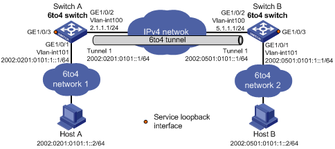
Requirements analysis
To enable communication between 6to4 networks, configure 6to4 addresses for 6to4 switches and hosts in the 6to4 networks.
· The IPv4 address of VLAN-interface 100 on Switch A is 2.1.1.1/24, and the corresponding 6to4 prefix is 2002:0201:0101::/48. Host A must use this prefix.
· The IPv4 address of VLAN-interface 100 on Switch B is 5.1.1.1/24, and the corresponding 6to4 prefix is 2002:0501:0101::/48. Host B must use this prefix.
Configuration procedure
Make sure Switch A and Switch B have the corresponding VLAN interfaces created and can reach each other through IPv4.
· Configure Switch A:
# Add GigabitEthernet 1/0/2 (the physical interface of the tunnel) to VLAN 100.
<SwitchA> system-view
[SwitchA] vlan 100
[SwitchA-vlan100] port gigabitethernet 1/0/2
[SwitchA-vlan100] quit
# Specify an IPv4 address for VLAN-interface 100.
[SwitchA] interface vlan-interface 100
[SwitchA-Vlan-interface100] ip address 2.1.1.1 24
[SwitchA-Vlan-interface100] quit
# Add GigabitEthernet 1/0/1 to VLAN 101.
[SwitchA] vlan 101
[SwitchA-vlan101] port gigabitethernet 1/0/1
[SwitchA-vlan101] quit
# Specify a 6to4 address for VLAN-interface 101.
[SwitchA] interface vlan-interface 101
[SwitchA-Vlan-interface101] ipv6 address 2002:0201:0101:1::1/64
[SwitchA-Vlan-interface101] quit
# Create service loopback group 1, and specify its service type as tunnel.
[SwitchA] service-loopback group 1 type tunnel
# Assign GigabitEthernet 1/0/3 to service loopback group 1.
[SwitchA] interface gigabitethernet 1/0/3
[SwitchA-GigabitEthernet1/0/3] port service-loopback group 1
[SwitchA-GigabitEthernet1/0/3] quit
# Create 6to4 tunnel interface Tunnel 1.
[SwitchA] interface tunnel 1 mode ipv6-ipv4 6to4
# Specify an IPv6 address for the tunnel interface.
[SwitchA-Tunnel1] ipv6 address 2002:0201:0101::1/64
# Specify the source interface as VLAN-interface 100 for the tunnel interface.
[SwitchA-Tunnel1] source vlan-interface 100
[SwitchA-Tunnel1] quit
# Configure a static route destined for 2002::/16 through the tunnel interface.
[SwitchA] ipv6 route-static 2002:: 16 tunnel 1
· Configure Switch B:
# Add GigabitEthernet 1/0/2 (the physical interface of the tunnel) to VLAN 100.
<SwitchB> system-view
[SwitchB] vlan 100
[SwitchB-vlan100] port gigabitethernet 1/0/2
[SwitchB-vlan100] quit
# Specify an IPv4 address for VLAN-interface 100.
[SwitchB] interface vlan-interface 100
[SwitchB-Vlan-interface100] ip address 5.1.1.1 24
[SwitchB-Vlan-interface100] quit
# Add GigabitEthernet 1/0/1 to VLAN 101.
[SwitchB] vlan 101
[SwitchB-vlan101] port gigabitethernet 1/0/1
[SwitchB-vlan101] quit
# Specify a 6to4 address for VLAN-interface 101.
[SwitchB] interface vlan-interface 101
[SwitchB-Vlan-interface101] ipv6 address 2002:0501:0101:1::1/64
[SwitchB-Vlan-interface101] quit
# Create service loopback group 1, and specify its service type as tunnel.
[SwitchB] service-loopback group 1 type tunnel
# Assign GigabitEthernet 1/0/3 to service loopback group 1.
[SwitchB] interface gigabitethernet 1/0/3
[SwitchB-GigabitEthernet1/0/3] port service-loopback group 1
[SwitchB-GigabitEthernet1/0/3] quit
# Create 6to4 tunnel interface Tunnel 1.
[SwitchB] interface tunnel 1 mode ipv6-ipv4 6to4
# Specify an IPv6 address for the tunnel interface.
[SwitchB-Tunnel1] ipv6 address 2002:0501:0101::1/64
# Specify the source interface as VLAN-interface 100 for the tunnel interface.
[SwitchB-Tunnel1] source vlan-interface 100
[SwitchB-Tunnel1] quit
# Configure a static route destined for 2002::/16 through the tunnel interface.
[SwitchB] ipv6 route-static 2002:: 16 tunnel 1
Verifying the configuration
# Verify that the Linux-running hosts Host A and Host B can ping each other.
D:\>ping6 -s 2002:201:101:1::2 2002:501:101:1::2
Pinging 2002:501:101:1::2
from 2002:201:101:1::2 with 32 bytes of data:
Reply from 2002:501:101:1::2: bytes=32 time=13ms
Reply from 2002:501:101:1::2: bytes=32 time=1ms
Reply from 2002:501:101:1::2: bytes=32 time=1ms
Reply from 2002:501:101:1::2: bytes=32 time<1ms
Ping statistics for 2002:501:101:1::2:
Packets: Sent = 4, Received = 4, Lost = 0 (0% loss),
Approximate round trip times in milli-seconds:
Minimum = 0ms, Maximum = 13ms, Average = 3ms
6to4 relay configuration example
Network requirements
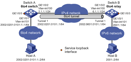
As shown in Figure 6, Switch A is a 6to4 switch, and 6to4 addresses are used on the connected IPv6 network. Switch B acts as a 6to4 relay switch and is connected to the IPv6 network (2001::/16). Configure a 6to4 tunnel between Switch A and Switch B to make Host A and Host B reachable to each other.
The configuration on a 6to4 relay switch is similar to that on a 6to4 switch. To enable communication between the 6to4 network and the IPv6 network, configure a route destined for the IPv6 network on the 6to4 switch. The IPv4 address of VLAN-interface 100 on the relay switch is 6.1.1.1/24 and its corresponding 6to4 prefix is 2002:0601:0101::/48. The next hop of the static route must be an address using this prefix.
Configuration procedure
Make sure Switch A and Switch B have the corresponding VLAN interfaces created and can reach each other through IPv4.
· Configure Switch A:
# Add GigabitEthernet 1/0/2 (the physical interface of the tunnel) to VLAN 100.
<SwitchA> system-view
[SwitchA] vlan 100
[SwitchA-vlan100] port gigabitethernet 1/0/2
[SwitchA-vlan100] quit
# Specify an IPv4 address for VLAN-interface 100.
[SwitchA] interface vlan-interface 100
[SwitchA-Vlan-interface100] ip address 2.1.1.1 255.255.255.0
[SwitchA-Vlan-interface100] quit
# Add GigabitEthernet 1/0/1 to VLAN 101.
[SwitchA] vlan 101
[SwitchA-vlan101] port gigabitethernet 1/0/1
[SwitchA-vlan101] quit
# Specify a 6to4 address for VLAN-interface 101.
[SwitchA] interface vlan-interface 101
[SwitchA-Vlan-interface101] ipv6 address 2002:0201:0101:1::1/64
[SwitchA-Vlan-interface101] quit
# Create service loopback group 1, and specify its service type as tunnel.
[SwitchA] service-loopback group 1 type tunnel
# Assign GigabitEthernet 1/0/3 to service loopback group 1.
[SwitchA] interface gigabitethernet 1/0/3
[SwitchA-GigabitEthernet1/0/3] port service-loopback group 1
[SwitchA-GigabitEthernet1/0/3] quit
# Create 6to4 tunnel interface Tunnel 1.
[SwitchA] interface tunnel 1 mode ipv6-ipv4 6to4
# Specify an IPv6 address for the tunnel interface.
[SwitchA-Tunnel1] ipv6 address 2002:0201:0101::1/64
# Specify the source interface as VLAN-interface 100 for the tunnel interface.
[SwitchA-Tunnel1] source vlan-interface 100
[SwitchA-Tunnel1] quit
# Configure a static route destined for the 6to4 relay switch.
[SwitchA] ipv6 route-static 2002:0601:0101:: 64 tunnel 1
# Configure a default route to reach the IPv6 network, which specifies the 6to4 address of the 6to4 relay switch as the next hop.
[SwitchA] ipv6 route-static :: 0 2002:0601:0101::1
· Configure Switch B:
# Add GigabitEthernet 1/0/2 (the physical interface of the tunnel) to VLAN 100.
<SwitchB> system-view
[SwitchB] vlan 100
[SwitchB-vlan100] port gigabitethernet 1/0/2
[SwitchB-vlan100] quit
# Specify an IPv4 address for VLAN-interface 100.
[SwitchB] interface vlan-interface 100
[SwitchB-Vlan-interface100] ip address 6.1.1.1 255.255.255.0
[SwitchB-Vlan-interface100] quit
# Add GigabitEthernet 1/0/1 to VLAN 101.
[SwitchB] vlan 101
[SwitchB-vlan101] port gigabitethernet 1/0/1
[SwitchB-vlan101] quit
# Specify an IPv6 address for VLAN-interface 101.
[SwitchB] interface vlan-interface 101
[SwitchB-Vlan-interface101] ipv6 address 2001::1/16
[SwitchB-Vlan-interface101] quit
# Create service loopback group 1, and specify its service type as tunnel.
[SwitchB] service-loopback group 1 type tunnel
# Assign GigabitEthernet 1/0/3 to service loopback group 1.
[SwitchB] interface gigabitethernet 1/0/3
[SwitchB-GigabitEthernet1/0/3] port service-loopback group 1
[SwitchB-GigabitEthernet1/0/3] quit
# Create 6to4 tunnel interface Tunnel 1.
[SwitchB] interface tunnel 1 mode ipv6-ipv4 6to4
# Specify an IPv6 address for the tunnel interface.
[SwitchB-Tunnel1] ipv6 address 2002:0601:0101::1/64
# Specify VLAN-interface 100 as the source interface of the tunnel interface.
[SwitchB-Tunnel1] source vlan-interface 100
[SwitchB-Tunnel1] quit
# Configure a static route destined for 2002::/16 through the tunnel interface.
[SwitchB] ipv6 route-static 2002:: 16 tunnel 1
Verifying the configuration
# Verify that the Linux-running hosts Host A and Host B can ping each other.
D:\>ping6 -s 2002:201:101:1::2 2001::2
Pinging 2001::2
from 2002:201:101:1::2 with 32 bytes of data:
Reply from 2001::2: bytes=32 time=13ms
Reply from 2001::2: bytes=32 time=1ms
Reply from 2001::2: bytes=32 time=1ms
Reply from 2001::2: bytes=32 time<1ms
Ping statistics for 2001::2:
Packets: Sent = 4, Received = 4, Lost = 0 (0% loss),
Approximate round trip times in milli-seconds:
Minimum = 0ms, Maximum = 13ms, Average = 3ms
Configuring an ISATAP tunnel
Follow these guidelines when you configure an ISATAP tunnel:
· You do not need to configure a destination address for an ISATAP tunnel, because the destination IPv4 address is embedded in the ISATAP address.
· Do not specify the same source addresses for local tunnel interfaces in the same tunnel mode.
· Because automatic tunnels do not support dynamic routing, configure a static route destined for the destination IPv6 network at each tunnel end. You can specify the local tunnel interface as the egress interface of the route or specify the IPv6 address of the peer tunnel interface as the next hop of the route. For more information about route configuration, see Layer 3—IP Routing Configuration Guide.
To configure an ISATAP tunnel:
|
Step |
Command |
Remarks |
|
1. Enter system view. |
system-view |
N/A |
|
2. Enter ISATAP tunnel interface view. |
interface tunnel number [ mode ipv6-ipv4 isatap ] |
N/A |
|
3. Specify an IPv6 address for the tunnel interface. |
See "Configuring basic IPv6 settings." |
By default, no IPv6 address is configured for the tunnel interface. |
|
4. Configure a source address or source interface for the tunnel interface. |
source { ipv4-address | interface-type interface-number } |
By default, no source address or source interface is configured for the tunnel interface. If you specify a source address, it is used as the source IP address of tunneled packets. If you specify a source interface, the primary IP address of this interface is used as the source IP address of tunneled packets. |
|
5. Disable RA message suppression. |
undo ipv6 nd ra halt |
By default, RA message suppression is enabled. |
|
6. (Optional.) Set the DF bit for tunneled packets. |
tunnel dfbit enable |
By default, the DF bit is not set for tunneled packets. |
|
7. Return to system view. |
quit |
N/A |
|
8. (Optional.) Enable dropping IPv6 packets that use IPv4-compatible IPv6 addresses. |
tunnel discard ipv4-compatible-packet |
By default, IPv6 packets that use IPv4-compatible IPv6 addresses are not dropped. |
Configuration example
Network requirements
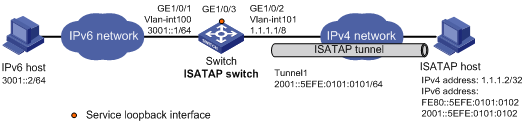
As shown in Figure 7, configure an ISATAP tunnel between the switch and the ISATAP host so the ISATAP host in the IPv4 network can access the IPv6 network.
Configuration procedure
· Configure the switch:
# Add GigabitEthernet 1/0/1 to VLAN 100.
<Switch> system-view
[Switch] vlan 100
[Switch-vlan100] port gigabitethernet 1/0/1
[Switch-vlan100] quit
# Specify an IPv6 address for VLAN-interface 100.
[Switch] interface vlan-interface 100
[Switch-Vlan-interface100] ipv6 address 3001::1/64
[Switch-Vlan-interface100] quit
# Add GigabitEthernet 1/0/2 (the physical interface of the tunnel) to VLAN 101.
[Switch] vlan 101
[Switch-vlan101] port gigabitethernet 1/0/2
[Switch-vlan101] quit
# Specify an IPv4 address for VLAN-interface 101.
[Switch] interface vlan-interface 101
[Switch-Vlan-interface101] ip address 1.1.1.1 255.0.0.0
[Switch-Vlan-interface101] quit
# Create service loopback group 1, and specify its service type as tunnel.
[Switch] service-loopback group 1 type tunnel
# Assign GigabitEthernet 1/0/3 to service loopback group 1.
[Switch] interface gigabitethernet 1/0/3
[Switch-GigabitEthernet1/0/3] port service-loopback group 1
[Switch-GigabitEthernet1/0/3] quit
# Create ISATAP tunnel interface Tunnel 1.
[Switch] interface tunnel 1 mode ipv6-ipv4 isatap
# Specify an EUI-64 IPv6 address for the tunnel interface.
[Switch-Tunnel1] ipv6 address 2001:: 64 eui-64
# Specify VLAN-interface 101 as the source interface of the tunnel interface.
[Switch-Tunnel1] source vlan-interface 101
# Disable RA message suppression so that the ISATAP host can acquire information such as the address prefix from the RA message advertised by the ISATAP switch.
[Switch-Tunnel1] undo ipv6 nd ra halt
[Switch-Tunnel1] quit
· Configure the ISATAP host:
Configurations on the ISATAP host vary by operating system. The following configuration is performed on Windows XP.
# Install IPv6.
C:\>ipv6 install
# On a host running Windows XP, the ISATAP interface is typically interface 2. Display information about the ISATAP interface.
C:\>ipv6 if 2
Interface 2: Automatic Tunneling Pseudo-Interface
Guid {48FCE3FC-EC30-E50E-F1A7-71172AEEE3AE}
does not use Neighbor Discovery
does not use Router Discovery
routing preference 1
EUI-64 embedded IPv4 address: 0.0.0.0
router link-layer address: 0.0.0.0
preferred link-local fe80::5efe:1.1.1.2, life infinite
link MTU 1280 (true link MTU 65515)
current hop limit 128
reachable time 42500ms (base 30000ms)
retransmission interval 1000ms
DAD transmits 0
default site prefix length 48
# Specify an IPv4 address for the ISATAP switch.
C:\>netsh interface ipv6 isatap set router 1.1.1.1
# Display information about the ISATAP interface.
C:\>ipv6 if 2
Interface 2: Automatic Tunneling Pseudo-Interface
Guid {48FCE3FC-EC30-E50E-F1A7-71172AEEE3AE}
does not use Neighbor Discovery
uses Router Discovery
routing preference 1
EUI-64 embedded IPv4 address: 1.1.1.2
router link-layer address: 1.1.1.1
preferred global 2001::5efe:1.1.1.2, life 29d23h59m46s/6d23h59m46s (public)
preferred link-local fe80::5efe:1.1.1.2, life infinite
link MTU 1500 (true link MTU 65515)
current hop limit 255
reachable time 42500ms (base 30000ms)
retransmission interval 1000ms
DAD transmits 0
default site prefix length 48
The host has obtained the address prefix 2001::/64 and has automatically generated the global unicast address 2001::5efe:1.1.1.2. The message "uses Router Discovery" indicates that the router discovery feature is enabled on the host.
# Display information about IPv6 routes on the host.
C:\>ipv6 rt
2001::/64 -> 2 pref 1if+8=9 life 29d23h59m43s (autoconf)
::/0 -> 2/fe80::5efe:1.1.1.1 pref 1if+256=257 life 29m43s (autoconf)
· On the IPv6 host, configure a route to the ISATAP switch.
C:\>netsh interface ipv6 set route 2001::/64 5 3001::1
Verifying the configuration
# Verify that the ISATAP host can ping the IPv6 host.
C:\>ping 3001::2
Pinging 3001::2 with 32 bytes of data:
Reply from 3001::2: time=1ms
Reply from 3001::2: time=1ms
Reply from 3001::2: time=1ms
Reply from 3001::2: time=1ms
Ping statistics for 3001::2:
Packets: Sent = 4, Received = 4, Lost = 0 (0% loss),
Approximate round trip times in milli-seconds:
Minimum = 1ms, Maximum = 1ms, Average = 1ms
IPv4 over IPv4 tunneling
Overview
IPv4 over IPv4 tunneling (RFC 1853) enables isolated IPv4 networks to communicate. For example, an IPv4 over IPv4 tunnel can connect isolated private IPv4 networks over a public IPv4 network.
Figure 8 IPv4 over IPv4 tunnel

Figure 8 shows the encapsulation and de-encapsulation processes.
· Encapsulation:
a. Device A receives an IP packet from an IPv4 host and submits it to the IP protocol stack.
b. The IPv4 protocol stack determines how to forward the packet according to the destination address in the IP header. If the packet is destined for the IPv4 host connected to Device B, Device A delivers the packet to the tunnel interface.
c. The tunnel interface adds a new IPv4 header to the IPv4 packet and submits it to the IP protocol stack.
In the new header, the source IP address specifies the tunnel source, and the destination IP address specifies the tunnel destination.
d. The IP protocol stack uses the destination IP address of the new IP header to look up the routing table, and then sends the packet out.
· De-encapsulation:
a. After receiving the packet, Device B delivers it to the IP protocol stack.
b. If the protocol number is 4 (indicating an IPv4 packet is encapsulated within the packet), the IP protocol stack delivers the packet to the tunnel module for de-encapsulation.
c. The tunnel module de-encapsulates the IP packet and sends it back to the IP protocol stack.
d. The protocol stack forwards the de-encapsulated packet.
Configuring an IPv4 over IPv4 tunnel
Follow these guidelines when you configure an IPv4 over IPv4 tunnel:
· The tunnel destination address specified on the local device must be identical with the tunnel source address specified on the tunnel peer device.
· Do not specify the same source and destination addresses for local tunnel interfaces in the same tunnel mode.
· The IPv4 address of the local tunnel interface cannot be on the same subnet as the destination address configured on the tunnel interface.
· To ensure correct packet forwarding, identify whether the destination IPv4 network and the IPv4 address of the local tunnel interface are on the same subnet. If they are not, configure a route reaching the destination IPv4 network through the tunnel interface. You can configure the route by using one of the following methods:
¡ Configure a static route, and specify the local tunnel interface as the egress interface or specify the IPv4 address of the peer tunnel interface as the next hop.
¡ Enable a dynamic routing protocol on both tunnel interfaces to achieve the same purpose.
For more information about route configuration, see Layer 3—IP Routing Configuration Guide.
· The destination address of the route passing the tunnel interface cannot be on the same subnet as the destination address configured on the tunnel interface.
To configure an IPv4 over IPv4 tunnel:
|
Step |
Command |
Remarks |
|
1. Enter system view. |
system-view |
N/A |
|
2. Enter IPv4 over IPv4 tunnel interface view. |
interface tunnel number [ mode ipv4-ipv4 ] |
N/A |
|
3. Configure an IPv4 address for the tunnel interface. |
ip address ip-address { mask | mask-length } [ sub ] |
By default, no IPv4 address is configured for the tunnel interface. |
|
4. Configure a source address or source interface for the tunnel interface. |
source { ipv4-address | interface-type interface-number } |
By default, no source address or source interface is configured for the tunnel interface. If you specify a source address, it is used as the source IP address of tunneled packets. If you specify a source interface, the primary IP address of this interface is used as the source IP address of tunneled packets. |
|
5. Configure a destination address for the tunnel interface. |
destination ipv4-address |
By default, no destination address is configured for the tunnel interface. The tunnel destination address must be the IP address of the receiving interface on the tunnel peer. It is used as the destination IP address of tunneled packets. |
|
6. (Optional.) Set the DF bit for tunneled packets. |
tunnel dfbit enable |
By default, the DF bit is not set for tunneled packets. |
Configuration example
Network requirements
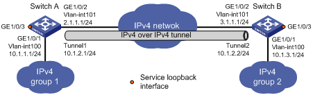
As shown in Figure 9, the two subnets IPv4 group 1 and IPv4 group 2 use private IPv4 addresses. Configure an IPv4 over IPv4 tunnel between Switch A and Switch B to make the two subnets reachable to each other.
Configuration procedure
Make sure Switch A and Switch B have the corresponding VLAN interfaces created and can reach each other through IPv4.
· Configure Switch A:
# Add GigabitEthernet 1/0/1 to VLAN 100.
<SwitchA> system-view
[SwitchA] vlan 100
[SwitchA-vlan100] port gigabitethernet 1/0/1
[SwitchA-vlan100] quit
# Specify an IPv4 address for VLAN-interface 100.
[SwitchA] interface vlan-interface 100
[SwitchA-Vlan-interface100] ip address 10.1.1.1 255.255.255.0
[SwitchA-Vlan-interface100] quit
# Add GigabitEthernet 1/0/2 (the physical interface of the tunnel) to VLAN 101.
[SwitchA] vlan 101
[SwitchA-vlan101] port gigabitethernet 1/0/2
[SwitchA-vlan101] quit
# Specify an IPv4 address for VLAN-interface 101.
[SwitchA] interface vlan-interface 101
[SwitchA-Vlan-interface101] ip address 2.1.1.1 255.255.255.0
[SwitchA-Vlan-interface101] quit
# Create service loopback group 1, and specify its service type as tunnel.
[SwitchA] service-loopback group 1 type tunnel
# Assign GigabitEthernet 1/0/3 to service loopback group 1.
[SwitchA] interface gigabitethernet 1/0/3
[SwitchA-GigabitEthernet1/0/3] port service-loopback group 1
[SwitchA-GigabitEthernet1/0/3] quit
# Create IPv4 over IPv4 tunnel interface Tunnel 1.
[SwitchA] interface tunnel 1 mode ipv4-ipv4
# Specify an IPv4 address for the tunnel interface.
[SwitchA-Tunnel1] ip address 10.1.2.1 255.255.255.0
# Specify the IP address of VLAN-interface 101 as the source address for the tunnel interface.
[SwitchA-Tunnel1] source 2.1.1.1
# Specify the IP address of VLAN-interface 101 on Switch B as the destination address for the tunnel interface.
[SwitchA-Tunnel1] destination 3.1.1.1
[SwitchA-Tunnel1] quit
# Configure a static route destined for IPv4 group 2 through the tunnel interface.
[SwitchA] ip route-static 10.1.3.0 255.255.255.0 tunnel 1
· Configure Switch B:
# Add GigabitEthernet 1/0/1 to VLAN 100.
<SwitchB> system-view
[SwitchB] vlan 100
[SwitchB-vlan100] port gigabitethernet 1/0/1
[SwitchB-vlan100] quit
# Specify an IPv4 address for VLAN-interface 100.
[SwitchB] interface vlan-interface 100
[SwitchB-Vlan-interface100] ip address 10.1.3.1 255.255.255.0
[SwitchB-Vlan-interface100] quit
# Add GigabitEthernet 1/0/2 (the physical interface of the tunnel) to VLAN 101.
[SwitchB] vlan 101
[SwitchB-vlan101] port gigabitethernet 1/0/2
[SwitchB-vlan101] quit
# Specify an IPv4 address for VLAN-interface 101.
[SwitchB] interface vlan-interface 101
[SwitchB-Vlan-interface101] ip address 3.1.1.1 255.255.255.0
[SwitchB-Vlan-interface101] quit
# Create service loopback group 1, and specify its service type as tunnel.
[SwitchB] service-loopback group 1 type tunnel
# Assign GigabitEthernet 1/0/3 to service loopback group 1.
[SwitchB] interface gigabitethernet 1/0/3
[SwitchB-GigabitEthernet1/0/3] port service-loopback group 1
[SwitchB-GigabitEthernet1/0/3] quit
# Create IPv4 over IPv4 tunnel interface Tunnel 2.
[SwitchB] interface tunnel 2 mode ipv4-ipv4
# Specify an IPv4 address for the tunnel interface.
[SwitchB-Tunnel2] ip address 10.1.2.2 255.255.255.0
# Specify the IP address of VLAN-interface 101 as the source address for the tunnel interface.
[SwitchB-Tunnel2] source 3.1.1.1
# Specify the IP address of VLAN-interface 101 on Switch A as the destination address for the tunnel interface.
[SwitchB-Tunnel2] destination 2.1.1.1
[SwitchB-Tunnel2] quit
# Configure a static route destined for IPv4 group 1 through the tunnel interface.
[SwitchB] ip route-static 10.1.1.0 255.255.255.0 tunnel 2
Verifying the configuration
# Use the display interface tunnel command to display the status of the tunnel interfaces on Switch A and Switch B. Verify that the tunnel interfaces are up. (Details not shown.)
# Verify that Switch A and Switch B can ping the IPv4 address of the peer interface VLAN-interface 100. This example uses Switch A.
[SwitchA] ping -a 10.1.1.1 10.1.3.1
Ping 10.1.3.1 (10.1.3.1) from 10.1.1.1: 56 data bytes, press CTRL_C to break
56 bytes from 10.1.3.1: icmp_seq=0 ttl=255 time=2.000 ms
56 bytes from 10.1.3.1: icmp_seq=1 ttl=255 time=1.000 ms
56 bytes from 10.1.3.1: icmp_seq=2 ttl=255 time=0.000 ms
56 bytes from 10.1.3.1: icmp_seq=3 ttl=255 time=1.000 ms
56 bytes from 10.1.3.1: icmp_seq=4 ttl=255 time=1.000 ms
--- Ping statistics for 10.1.3.1 ---
5 packet(s) transmitted, 5 packet(s) received, 0.0% packet loss
round-trip min/avg/max/std-dev = 0.000/1.000/2.000/0.632 ms
IPv4 over IPv6 tunneling
Overview
Implementation
IPv4 over IPv6 tunneling adds an IPv6 header to IPv4 packets so that the IPv4 packets can pass an IPv6 network through a tunnel to realize interworking between isolated IPv4 networks.
Figure 10 IPv4 over IPv6 tunnel

Figure 10 shows the encapsulation and de-encapsulation processes.
· Encapsulation:
a. Upon receiving an IPv4 packet, Device A delivers it to the IPv4 protocol stack.
b. The IPv4 protocol stack uses the destination address of the packet to determine the egress interface. If the egress interface is the tunnel interface, the IPv4 protocol stack delivers the packet to the tunnel interface.
c. The tunnel interface adds an IPv6 header to the original IPv4 packet and delivers the packet to the IPv6 protocol stack.
d. The IPv6 protocol stack uses the destination IPv6 address of the packet to look up the routing table, and then sends it out.
· De-encapsulation:
a. Upon receiving the IPv6 packet from the attached IPv6 network, Device B delivers the packet to the IPv6 protocol stack to examine the protocol type encapsulated in the data portion of the packet.
b. If the protocol type is IPv4, the IPv6 protocol stack delivers the packet to the tunneling module.
c. The tunneling module removes the IPv6 header and delivers the remaining IPv4 packet to the IPv4 protocol stack.
d. The IPv4 protocol stack forwards the IPv4 packet.
Tunnel modes
Only the IPv4 over IPv6 manual tunnel mode is available.
An IPv4 over IPv6 manual tunnel is a point-to-point link and its source and destination IPv6 addresses are manually configured. You can establish an IPv4 over IPv6 manual tunnel to connect isolated IPv4 networks over an IPv6 network.
Configuring an IPv4 over IPv6 manual tunnel
Follow these guidelines when you configure an IPv4 over IPv6 manual tunnel:
· The tunnel destination address specified on the local device must be identical with the tunnel source address specified on the tunnel peer device.
· Do not specify the same source and destination addresses for local tunnel interfaces in the same tunnel mode.
· To ensure correct packet forwarding, identify whether the destination IPv4 network and the IPv4 address of the local tunnel interface are on the same subnet. If they are not, configure a route reaching the destination IPv4 network through the tunnel interface. You can configure the route by using one of the following methods:
¡ Configure a static route, and specify the local tunnel interface as the egress interface or specify the IPv6 address of the peer tunnel interface as the next hop.
¡ Enable a dynamic routing protocol on both tunnel interfaces to achieve the same purpose.
For more information about route configuration, see Layer 3—IP Routing Configuration Guide.
To configure an IPv4 over IPv6 manual tunnel:
|
Step |
Command |
Remarks |
|
1. Enter system view. |
system-view |
N/A |
|
2. Enter IPv6 tunnel interface view. |
interface tunnel number [ mode ipv6 ] |
N/A |
|
3. Configure an IPv4 address for the tunnel interface. |
ip address ip-address { mask | mask-length } [ sub ] |
By default, no IPv4 address is configured for the tunnel interface. |
|
4. Configure the source address or interface for the tunnel interface. |
source { ipv6-address | interface-type interface-number } |
By default, no source address or interface is configured for the tunnel. If you specify a source address, it is used as the source IPv6 address of tunneled packets. If you specify a source interface, the lowest IPv6 address of this interface is used as the source IPv6 address of tunneled packets. |
|
5. Configure the destination address for the tunnel interface. |
destination ipv6-address |
By default, no destination address is configured for the tunnel. The tunnel destination address must be the IPv6 address of the receiving interface on the tunnel peer. It is used as the destination IPv6 address of tunneled packets. |
Configuration example
Network requirements
As shown in Figure 11, configure an IPv4 over IPv6 manual tunnel between Switch A and Switch B so the two networks can reach each other over the IPv6 network.
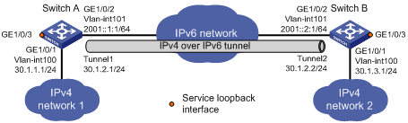
Configuration procedure
Make sure Switch A and Switch B have the corresponding VLAN interfaces created and can reach each other through IPv6.
· Configure Switch A:
# Add GigabitEthernet 1/0/1 to VLAN 100.
<SwitchA> system-view
[SwitchA] vlan 100
[SwitchA-vlan100] port gigabitethernet 1/0/1
[SwitchA-vlan100] quit
# Specify an IPv4 address for VLAN-interface 100.
[SwitchA] interface vlan-interface 100
[SwitchA-Vlan-interface100] ip address 30.1.1.1 255.255.255.0
[SwitchA-Vlan-interface100] quit
# Add GigabitEthernet 1/0/2 (the physical interface of the tunnel) to VLAN 101.
[SwitchA] vlan 101
[SwitchA-vlan101] port gigabitethernet 1/0/2
[SwitchA-vlan101] quit
# Specify an IPv6 address for VLAN-interface 101.
[SwitchA] interface vlan-interface 101
[SwitchA-Vlan-interface101] ipv6 address 2001::1:1 64
[SwitchA-Vlan-interface101] quit
# Create service loopback group 1, and specify its service type as tunnel.
[SwitchA] service-loopback group 1 type tunnel
# Assign GigabitEthernet 1/0/3 to service loopback group 1.
[SwitchA] interface gigabitethernet 1/0/3
[SwitchA-GigabitEthernet1/0/3] port service-loopback group 1
[SwitchA-GigabitEthernet1/0/3] quit
# Create IPv6 tunnel interface Tunnel 1.
[SwitchA] interface tunnel 1 mode ipv6
# Specify an IPv4 address for the tunnel interface.
[SwitchA-Tunnel1] ip address 30.1.2.1 255.255.255.0
# Specify the IP address of VLAN-interface 101 as the source address for the tunnel interface.
[SwitchA-Tunnel1] source 2001::1:1
# Specify the IP address of VLAN-interface 101 on Switch B as the destination address for the tunnel interface.
[SwitchA-Tunnel1] destination 2001::2:1
[SwitchA-Tunnel1] quit
# Configure a static route destined for IPv4 network 2 through the tunnel interface.
[SwitchA] ip route-static 30.1.3.0 255.255.255.0 tunnel 1
· Configure Switch B:
# Add GigabitEthernet 1/0/1 to VLAN 100.
<SwitchB> system-view
[SwitchB] vlan 100
[SwitchB-vlan100] port gigabitethernet 1/0/1
[SwitchB-vlan100] quit
# Specify an IPv4 address for VLAN-interface 100.
[SwitchB] interface vlan-interface 100
[SwitchB-Vlan-interface100] ip address 30.1.3.1 255.255.255.0
[SwitchB-Vlan-interface100] quit
# Add GigabitEthernet 1/0/2 (the physical interface of the tunnel) to VLAN 101.
[SwitchB] vlan 101
[SwitchB-vlan101] port gigabitethernet 1/0/2
[SwitchB-vlan101] quit
# Specify an IPv6 address for VLAN-interface 101.
[SwitchB] interface vlan-interface 101
[SwitchB-Vlan-interface101] ipv6 address 2001::2:1 64
[SwitchB-Vlan-interface101] quit
# Create service loopback group 1, and specify its service type as tunnel.
[SwitchB] service-loopback group 1 type tunnel
# Assign GigabitEthernet 1/0/3 to service loopback group 1.
[SwitchB] interface gigabitethernet 1/0/3
[SwitchB-GigabitEthernet1/0/3] port service-loopback group 1
[SwitchB-GigabitEthernet1/0/3] quit
# Create IPv6 tunnel interface Tunnel 2.
[SwitchB] interface tunnel 2 mode ipv6
# Specify an IPv4 address for the tunnel interface.
[SwitchB-Tunnel2] ip address 30.1.2.2 255.255.255.0
# Specify the IP address of VLAN-interface 101 as the source address for the tunnel interface (IP address of VLAN-interface 101).
[SwitchB-Tunnel2] source 2001::2:1
# Specify the IP address of VLAN-interface 101 on Switch A as the destination address for the tunnel interface.
[SwitchB-Tunnel2] destination 2001::1:1
[SwitchB-Tunnel2] quit
# Configure a static route destined for IPv4 network 1 through the tunnel interface.
[SwitchB] ip route-static 30.1.1.0 255.255.255.0 tunnel 2
Verifying the configuration
# Use the display interface tunnel command to display the status of the tunnel interfaces on Switch A and Switch B. Verify that the tunnel interfaces are up. (Details not shown.)
# Verify that Switch A and Switch B can ping the IPv4 address of the peer interface. This example uses Switch A.
[SwitchA] ping -a 30.1.1.1 30.1.3.1
Ping 30.1.3.1 (30.1.3.1) from 30.1.1.1: 56 data bytes, press CTRL_C to break
56 bytes from 30.1.3.1: icmp_seq=0 ttl=255 time=3.000 ms
56 bytes from 30.1.3.1: icmp_seq=1 ttl=255 time=1.000 ms
56 bytes from 30.1.3.1: icmp_seq=2 ttl=255 time=0.000 ms
56 bytes from 30.1.3.1: icmp_seq=3 ttl=255 time=1.000 ms
56 bytes from 30.1.3.1: icmp_seq=4 ttl=255 time=1.000 ms
--- Ping statistics for 30.1.3.1 ---
5 packet(s) transmitted, 5 packet(s) received, 0.0% packet loss
round-trip min/avg/max/std-dev = 0.000/1.200/3.000/0.980 ms
IPv6 over IPv6 tunneling
Overview
IPv6 over IPv6 tunneling (RFC 2473) enables isolated IPv6 networks to communicate with each other over another IPv6 network. For example, two isolated IPv6 networks that do not want to show their addresses to the Internet can use an IPv6 over IPv6 tunnel to communicate with each other.
Figure 12 Principle of IPv6 over IPv6 tunneling
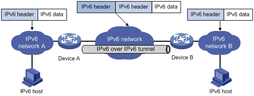
Figure 12 shows the encapsulation and de-encapsulation processes.
· Encapsulation:
a. After receiving an IPv6 packet, Device A submits it to the IPv6 protocol stack.
b. The IPv6 protocol stack uses the destination IPv6 address of the packet to find the egress interface. If the egress interface is the tunnel interface, the stack delivers it to the tunnel interface.
c. After receiving the packet, the tunnel interface adds an IPv6 header to it and submits it to the IPv6 protocol stack.
d. The IPv6 protocol stack forwards the packet according to its destination IPv6 address.
· De-encapsulation:
a. Upon receiving the IPv6 packet, Device B delivers it to the IPv6 protocol stack.
b. The IPv6 protocol stack checks the protocol type of the data portion encapsulated in the IPv6 packet. If the encapsulation protocol is IPv6, the stack delivers the packet to the tunnel module.
c. The tunnel module de-encapsulates the packet and sends it back to the IPv6 protocol stack.
d. The IPv6 protocol stack forwards the IPv6 packet.
Configuring an IPv6 over IPv6 tunnel
Follow these guidelines when you configure an IPv6 over IPv6 tunnel:
· The tunnel destination address specified on the local device must be identical with the tunnel source address specified on the tunnel peer device.
· Do not specify the same source and destination addresses for local tunnel interfaces in the same tunnel mode.
· The IPv6 address of the tunnel interface cannot be on the same subnet as the destination address configured for the tunnel interface.
· To ensure correct packet forwarding, identify whether the destination IPv6 network and the IPv6 address of the local tunnel interface are on the same subnet. If they are not, configure a route reaching the destination IPv6 network through the tunnel interface. You can configure the route by using one of the following methods:
¡ Configure a static route, and specify the local tunnel interface as the egress interface or specify the IPv6 address of the peer tunnel interface as the next hop.
¡ Enable a dynamic routing protocol on both tunnel interfaces to achieve the same purpose.
For more information about route configuration, see Layer 3—IP Routing Configuration Guide.
· The destination address of the route passing the tunnel interface cannot be on the same subnet as the destination address configured for the tunnel interface.
To configure an IPv6 over IPv6 tunnel:
|
Step |
Command |
Remarks |
|
1. Enter system view. |
system-view |
N/A |
|
2. Enter IPv6 tunnel interface view. |
interface tunnel number [ mode ipv6 ] |
N/A |
|
3. Configure an IPv6 address for the tunnel interface. |
See "Configuring basic IPv6 settings." |
By default, no IPv6 address is configured for the tunnel interface. |
|
4. Configure the source address or source interface for the tunnel interface. |
source { ipv6-address | interface-type interface-number } |
By default, no source address or interface is configured for the tunnel. If you specify a source address, it is used as the source IPv6 address of tunneled packets. If you specify a source interface, the lowest IPv6 address of this interface is used as the source IPv6 address of tunneled packets. |
|
5. Configure the destination address for the tunnel interface. |
destination ipv6-address |
By default, no destination address is configured for the tunnel. The tunnel destination address must be the IPv6 address of the receiving interface on the tunnel peer. It is used as the destination IPv6 address of tunneled packets. |
|
6. Return to system view. |
quit |
N/A |
|
7. (Optional.) Enable dropping IPv6 packets that use IPv4-compatible IPv6 addresses. |
tunnel discard ipv4-compatible-packet |
By default, IPv6 packets that use IPv4-compatible IPv6 addresses are not dropped. |
Configuration example
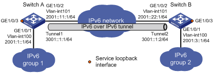
Network requirements
As shown in Figure 13, configure an IPv6 over IPv6 tunnel between Switch A and Switch B so the two networks can reach each other without disclosing their IPv6 addresses.
Configuration procedure
Make sure Switch A and Switch B have the corresponding VLAN interfaces created and can reach each other through IPv6.
· Configure Switch A:
# Add GigabitEthernet 1/0/1 to VLAN 100.
<SwitchA> system-view
[SwitchA] vlan 100
[SwitchA-vlan100] port gigabitethernet 1/0/1
[SwitchA-vlan100] quit
# Specify an IPv6 address for VLAN-interface 100.
[SwitchA] interface vlan-interface 100
[SwitchA-Vlan-interface100] ipv6 address 2001:1::1 64
[SwitchA-Vlan-interface100] quit
# Add GigabitEthernet 1/0/2 (the physical interface of the tunnel) to VLAN 101.
[SwitchA] vlan 101
[SwitchA-vlan101] port gigabitethernet 1/0/2
[SwitchA-vlan101] quit
# Specify an IPv6 address for VLAN-interface 101.
[SwitchA] interface vlan-interface 101
[SwitchA-Vlan-interface101] ipv6 address 2001::11:1 64
[SwitchA-Vlan-interface101] quit
# Create service loopback group 1, and specify its service type as tunnel.
[SwitchA] service-loopback group 1 type tunnel
# Assign GigabitEthernet 1/0/3 to service loopback group 1.
[SwitchA] interface gigabitethernet 1/0/3
[SwitchA-GigabitEthernet1/0/3] port service-loopback group 1
[SwitchA-GigabitEthernet1/0/3] quit
# Create IPv6 tunnel interface Tunnel 1.
[SwitchA] interface tunnel 1 mode ipv6
# Specify an IPv6 address for the tunnel interface.
[SwitchA-Tunnel1] ipv6 address 3001::1:1 64
# Specify the IP address of VLAN-interface 101 as the source address for the tunnel interface.
[SwitchA-Tunnel1] source 2001::11:1
# Specify the IP address of VLAN-interface 101 on Switch B as the destination address for the tunnel interface.
[SwitchA-Tunnel1] destination 2001::22:1
[SwitchA-Tunnel1] quit
# Configure a static route destined for the IPv6 network group 2 through the tunnel interface.
[SwitchA] ipv6 route-static 2001:3:: 64 tunnel 1
· Configure Switch B:
# Add GigabitEthernet 1/0/1 to VLAN 100.
<SwitchB> system-view
[SwitchB] vlan 100
[SwitchB-vlan100] port gigabitethernet 1/0/1
[SwitchB-vlan100] quit
# Specify an IPv6 address for VLAN-interface 100.
[SwitchB] interface vlan-interface 100
[SwitchB-Vlan-interface100] ipv6 address 2001:3::1 64
[SwitchB-Vlan-interface100] quit
# Add GigabitEthernet 1/0/2 (the physical interface of the tunnel) to VLAN 101.
[SwitchB] vlan 101
[SwitchB-vlan101] port gigabitethernet 1/0/2
[SwitchB-vlan101] quit
# Specify an IPv6 address for VLAN-interface 101.
[SwitchB] interface vlan-interface 101
[SwitchB-Vlan-interface101] ipv6 address 2001::22:1 64
[SwitchB-Vlan-interface101] quit
# Create service loopback group 1, and specify its service type as tunnel.
[SwitchB] service-loopback group 1 type tunnel
# Assign GigabitEthernet 1/0/3 to service loopback group 1.
[SwitchB] interface gigabitethernet 1/0/3
[SwitchB-GigabitEthernet1/0/3] port service-loopback group 1
[SwitchB-GigabitEthernet1/0/3] quit
# Create IPv6 tunnel interface Tunnel 2.
[SwitchB] interface tunnel 2 mode ipv6
# Specify an IPv6 address for the tunnel interface.
[SwitchB-Tunnel2] ipv6 address 3001::1:2 64
# Specify the IP address of VLAN-interface 101 as the source address for the tunnel interface.
[SwitchB-Tunnel2] source 2001::22:1
# Specify the IP address of VLAN-interface 101 on Switch A as the destination address for the tunnel interface.
[SwitchB-Tunnel2] destination 2001::11:1
[SwitchB-Tunnel2] quit
# Configure a static route destined for the IPv6 network group 1 through the tunnel interface.
[SwitchB] ipv6 route-static 2001:1:: 64 tunnel 2
Verifying the configuration
# Use the display ipv6 interface command to display the status of the tunnel interfaces on Switch A and Switch B. Verify that the tunnel interfaces are up. (Details not shown.)
# Verify that Switch A and Switch B can ping the IPv4 address of the peer interface. This example uses Switch A.
[SwitchA] ping ipv6 -a 2001:1::1 2001:3::1
Ping6(56 data bytes) 2001:1::1 --> 2001:3::1, press CTRL_C to break
56 bytes from 2001:3::1, icmp_seq=0 hlim=64 time=9.000 ms
56 bytes from 2001:3::1, icmp_seq=1 hlim=64 time=1.000 ms
56 bytes from 2001:3::1, icmp_seq=2 hlim=64 time=0.000 ms
56 bytes from 2001:3::1, icmp_seq=3 hlim=64 time=0.000 ms
56 bytes from 2001:3::1, icmp_seq=4 hlim=64 time=0.000 ms
--- Ping6 statistics for 2001:3::1 ---
5 packet(s) transmitted, 5 packet(s) received, 0.0% packet loss
round-trip min/avg/max/std-dev = 0.000/2.000/9.000/3.521 ms