- Table of Contents
-
- 05-Layer 3 - IP Services Configuration Guide
- 00-Preface
- 01-ARP configuration
- 02-IP addressing configuration
- 03-DHCP configuration
- 04-DNS configuration
- 05-IP forwarding basics configuration
- 06-Fast forwarding configuration
- 07-Adjacency table configuration
- 08-IRDP configuration
- 09-IP performance optimization configuration
- 10-UDP Helper configuration
- 11-IPv6 basics configuration
- 12-DHCPv6 configuration
- 13-IPv6 fast forwarding configuration
- 14-Tunneling configuration
- 15-GRE configuration
- 16-HTTP redirect configuration
- Related Documents
-
| Title | Size | Download |
|---|---|---|
| 01-ARP configuration | 324.89 KB |
Configuring a static ARP entry
Configuring a multiport ARP entry
Setting the maximum number of dynamic ARP entries for a device
Setting the maximum number of dynamic ARP entries for an interface
Setting the aging timer for dynamic ARP entries
Setting the maximum number of probes for dynamic ARP entries
Enabling dynamic ARP entry check
Configuring a customer-side port
Enabling recording user IP address conflicts
Displaying and maintaining ARP
Long static ARP entry configuration example
Short static ARP entry configuration example
Multiport ARP entry configuration example
Gratuitous ARP packet learning
Periodic sending of gratuitous ARP packets
Enabling IP conflict notification
Configuring gratuitous ARP packet retransmission for the device MAC address change
Common proxy ARP configuration example
Displaying and maintaining ARP snooping
ARP fast-reply configuration example
Configuring ARP proxy forwarding
Configuring ARP direct route advertisement
Mechanism of ARP direct route advertisement
Application in L2VPN access to L3VPN networks
Enabling ARP direct route advertisement
Configuring ARP
Overview
ARP resolves IP addresses into MAC addresses on Ethernet networks.
ARP message format
ARP uses two types of messages: ARP request and ARP reply. Figure 1 shows the format of ARP request/reply messages. Numbers in the figure refer to field lengths.
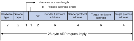
· Hardware type—Hardware address type. The value 1 represents Ethernet.
· Protocol type—Type of the protocol address to be mapped. The hexadecimal value 0x0800 represents IP.
· Hardware address length and protocol address length—Length, in bytes, of a hardware address and a protocol address. For an Ethernet address, the value of the hardware address length field is 6. For an IPv4 address, the value of the protocol address length field is 4.
· OP—Operation code, which describes the type of ARP message. The value 1 represents an ARP request, and the value 2 represents an ARP reply.
· Sender hardware address—Hardware address of the device sending the message.
· Sender protocol address—Protocol address of the device sending the message.
· Target hardware address—Hardware address of the device to which the message is being sent.
· Target protocol address—Protocol address of the device to which the message is being sent.
ARP operating mechanism
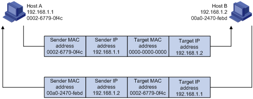
As shown in Figure 2, Host A and Host B are on the same subnet. Host A sends a packet to Host B as follows:
1. Host A looks through the ARP table for an ARP entry for Host B. If one entry is found, Host A uses the MAC address in the entry to encapsulate the IP packet into a data link layer frame. Then Host A sends the frame to Host B.
2. If Host A finds no entry for Host B, Host A buffers the packet and broadcasts an ARP request. The payload of the ARP request contains the following information:
¡ Sender IP address and sender MAC address—Host A's IP address and MAC address.
¡ Target IP address—Host B's IP address.
¡ Target MAC address—An all-zero MAC address.
All hosts on this subnet can receive the broadcast request, but only the requested host (Host B) processes the request.
3. Host B compares its own IP address with the target IP address in the ARP request. If they are the same, Host B operates as follows:
a. Adds the sender IP address and sender MAC address into its ARP table.
b. Encapsulates its MAC address into an ARP reply.
c. Unicasts the ARP reply to Host A.
4. After receiving the ARP reply, Host A operates as follows:
a. Adds the MAC address of Host B into its ARP table.
b. Encapsulates the MAC address into the packet and sends the packet to Host B.
Figure 2 ARP address resolution process
If Host A and Host B are on different subnets, Host A sends a packet to Host B as follows:
1. Host A broadcasts an ARP request where the target IP address is the IP address of the gateway.
2. The gateway responds with its MAC address in an ARP reply to Host A.
3. Host A uses the gateway's MAC address to encapsulate the packet, and then sends the packet to the gateway.
4. If the gateway has an ARP entry for Host B, it forwards the packet to Host B directly. If not, the gateway broadcasts an ARP request, in which the target IP address is the IP address of Host B.
5. After the gateway gets the MAC address of Host B, it sends the packet to Host B.
ARP table
An ARP table stores dynamic, static, OpenFlow, and Rule ARP entries.
Dynamic ARP entry
ARP automatically creates and updates dynamic entries. A dynamic ARP entry is removed when its aging timer expires or the output interface goes down. In addition, a dynamic ARP entry can be overwritten by a static ARP entry.
Static ARP entry
A static ARP entry is manually configured and maintained. It does not age out and cannot be overwritten by any dynamic ARP entry.
Static ARP entries protect communication between devices because attack packets cannot modify the IP-to-MAC mapping in a static ARP entry.
The device supports the following types of static ARP entries:
· Long static ARP entry—It contains the IP address, MAC address, and one of the following combinations:
¡ VLAN and output interface.
¡ Input and output interfaces.
A long static ARP entry is directly used for forwarding packets.
· Short static ARP entry—It contains only the IP address and MAC address.
¡ If the output interface is a Layer 3 Ethernet interface, the short ARP entry can be directly used to forward packets.
¡ If the output interface is a VLAN interface, the device sends an ARP request whose target IP address is the IP address in the short entry. If the sender IP and MAC addresses in the received ARP reply match the short static ARP entry, the device performs the following operations:
- Adds the interface that received the ARP reply to the short static ARP entry.
- Uses the resolved short static ARP entry to forward IP packets.
· Multiport ARP entry—It contains the IP address, MAC address, and VLAN.
The device can use a multiport ARP entry that has the same MAC address and VLAN as a multicast or multiport unicast MAC address entry for packet forwarding. A multiport ARP entry is manually configured. It does not age out and cannot be overwritten by any dynamic ARP entry. For more information about multicast MAC, see IP Multicast Configuration Guide.
To communicate with a host by using a fixed IP-to-MAC mapping, configure a short static ARP entry on the device. To communicate with a host by using a fixed IP-to-MAC mapping through an interface in a VLAN, configure a long static ARP entry on the device.
OpenFlow ARP entry
ARP creates OpenFlow ARP entries by learning from the OpenFlow module. An OpenFlow ARP entry does not age out, and it cannot be updated. An OpenFlow ARP entry can be used directly to forward packets. For more information about OpenFlow, see OpenFlow Configuration Guide.
Rule ARP entry
ARP creates Rule ARP entries by learning from the portal, VXLAN, and OVSDB modules. A Rule ARP entry does not age out, and it cannot be updated. It can be overwritten by a static ARP entry. A Rule ARP entry can be used directly to forward packets.
For more information about portal, see Security Configuration Guide. For more information about VXLAN and OVSDB, see VXLAN Configuration Guide.
Configuring a static ARP entry
Static ARP entries are effective when the device functions correctly.
A resolved short static ARP entry becomes unresolved upon certain events, for example, when the resolved output interface goes down, or the corresponding VLAN or VLAN interface is deleted.
Long static ARP entries can be effective or ineffective. Ineffective long static ARP entries cannot be used for packet forwarding. A long static ARP entry is ineffective when any of the following conditions exists:
· The corresponding VLAN interface or output interface is down.
· The IP address in the entry conflicts with a local IP address.
· No local interface has an IP address in the same subnet as the IP address in the ARP entry.
A long static ARP entry in a VLAN is deleted if the VLAN or VLAN interface is deleted.
To configure a static ARP entry:
|
Step |
Command |
Remarks |
|
1. Enter system view. |
system-view |
N/A |
|
2. Configure a static ARP entry. |
· Configure a long static ARP entry: · Configure a short static ARP entry: |
By default, no static ARP entries exist. |
Configuring a multiport ARP entry
A multiport ARP entry contains an IP address, MAC address, and VLAN ID.
For multiport ARP entries to be effective for packet forwarding, make sure the following conditions are met:
· A multicast or multiport unicast MAC address entry is configured to specify multiple output interfaces. The MAC address entry must have the same MAC address and VLAN ID as the multiport ARP entry. In addition, the IP address in the multiport ARP entry must reside on the same subnet as the VLAN interface of the specified VLAN.
· A service loopback group is created to support the multiport ARP service. The service loopback group has a minimum of one member port. For information about creating and configuring a service loopback group, see Layer 2—LAN Switching Configuration Guide.
A multiport ARP entry can overwrite a dynamic, short static or long static ARP entry. Conversely, a short static or long static ARP entry can overwrite a multiport ARP entry.
To configure a multiport ARP entry:
|
Step |
Command |
Remarks |
|
1. Enter system view. |
system-view |
N/A |
|
2. Configure a multicast or multiport unicast MAC address entry. |
· Configure a multiport unicast MAC address
entry: · Configure a multicast MAC address entry: |
By default, no multicast or multiport unicast MAC address entries exist. For more information about the mac-address multiport command, see Layer 2—LAN Switching Command Reference. For more information about the mac-address multicast command, see IP Multicast Command Reference. |
|
3. Configure a multiport ARP entry. |
arp multiport ip-address mac-address vlan-id [ vpn-instance vpn-instance-name ] |
By default, no multiport ARP entries exist. |
Setting the maximum number of dynamic ARP entries for a device
A device can dynamically learn ARP entries. To prevent a device from holding too many ARP entries, you can set the maximum number of dynamic ARP entries that the device can learn. When the maximum number is reached, the device stops learning ARP entries.
If you set a value lower than the number of existing dynamic ARP entries, the device does not remove the existing entries unless they are aged out. To clear dynamic ARP entries, use the reset arp dynamic command.
To set the maximum number of dynamic ARP entries for a device:
|
Step |
Command |
Remarks |
|
1. Enter system view. |
system-view |
N/A |
|
2. Set the maximum number of dynamic ARP entries for the device. |
· In standalone mode: · In IRF mode: |
By default, the maximum number of dynamic ARP entries that a device can learn depends on the maximum free space of the ARP table. This feature is not supported on the switching fabric modules. To disable the device from learning dynamic ARP entries, set the number to 0. |
Setting the maximum number of dynamic ARP entries for an interface
An interface can dynamically learn ARP entries. To prevent an interface from holding too many ARP entries, you can set the maximum number of dynamic ARP entries that the interface can learn. When the maximum number is reached, the interface stops learning ARP entries.
You can set limits for both a Layer 2 interface and the VLAN interface for a permitted VLAN on the Layer 2 interface. The Layer 2 interface learns an ARP entry only when neither limit is reached.
The total number of dynamic ARP entries that all interfaces learn will not be larger than the maximum number of dynamic ARP entries set for the device.
To set the maximum number of dynamic ARP entries for an interface:
|
Step |
Command |
Remarks |
|
1. Enter system view. |
system-view |
N/A |
|
2. Enter interface view. |
interface interface-type interface-number |
N/A |
|
3. Set the maximum number of dynamic ARP entries for the interface. |
arp max-learning-num max-number [ alarm alarm-threshold ] |
By default, the maximum number of dynamic ARP entries that an interface can learn depends on the maximum free space of the ARP table. To disable the interface from learning dynamic ARP entries, set the number to 0. |
Setting the aging timer for dynamic ARP entries
Each dynamic ARP entry in the ARP table has a limited lifetime, called an aging timer. The aging timer of a dynamic ARP entry is reset each time the dynamic ARP entry is updated. A dynamic ARP entry that is not updated before its aging timer expires is deleted from the ARP table.
You can set the maximum number of probes in system view or in interface view. The probe count set in interface view takes precedence over the probe count set in system view.
To set the aging timer for dynamic ARP entries in system view:
|
Step |
Command |
Remarks |
|
1. Enter system view. |
system-view |
N/A |
|
2. Set the aging timer for dynamic ARP entries. |
arp timer aging { aging-minutes | second aging-seconds } |
By default, the aging timer for dynamic ARP entries in system view is 20 minutes. |
To set the aging timer for dynamic ARP entries in interface view:
|
Step |
Command |
Remarks |
|
1. Enter system view. |
system-view |
N/A |
|
2. Enter interface view. |
interface interface-type interface-number |
N/A |
|
3. Set the aging timer for dynamic ARP entries. |
arp timer aging { aging-minutes | second aging-seconds } |
By default, the aging timer for dynamic ARP entries in interface view is the aging timer set in system view. |
Setting the maximum number of probes for dynamic ARP entries
This probe feature sends ARP requests to the IP address in a dynamic ARP entry. If the device receives an ARP reply before the entry aging timer expires, the device resets the aging timer. If the device does not receive any ARP reply after the maximum number of probes is made, the device deletes the entry when the entry aging timer expires. This probe mechanism keeps legal dynamic ARP entries valid and avoids unnecessary ARP resolution during later traffic forwarding.
You can set the maximum number of probes in system view or in interface view. The probe count set in interface view takes precedence over the probe count set in system view.
To set the maximum number of probes for dynamic ARP entries in system view:
|
Step |
Command |
Remarks |
|
1. Enter system view. |
system-view |
N/A |
|
2. Set the maximum number of probes for dynamic ARP entries. |
arp timer aging probe-count count |
By default, the maximum number of probes in system view for dynamic ARP entries is 3. |
To set the maximum number of probes for dynamic ARP entries in interface view:
|
Step |
Command |
Remarks |
|
1. Enter system view. |
system-view |
N/A |
|
2. Enter interface view. |
interface interface-type interface-number |
N/A |
|
3. Set the maximum number of probes for dynamic ARP entries. |
arp timer aging probe-count count |
By default, the maximum number of probes in interface view for dynamic ARP entries is the maximum number of probes set in system view. |
Enabling dynamic ARP entry check
The dynamic ARP entry check feature disables the device from supporting dynamic ARP entries that contain multicast MAC addresses. The device cannot learn dynamic ARP entries containing multicast MAC addresses. You cannot manually add static ARP entries containing multicast MAC addresses.
When dynamic ARP entry check is disabled, ARP entries containing multicast MAC addresses are supported. The device can learn dynamic ARP entries containing multicast MAC addresses obtained from the ARP packets sourced from a unicast MAC address. You can also manually add static ARP entries containing multicast MAC addresses.
To enable dynamic ARP entry check:
|
Step |
Command |
Remarks |
|
1. Enter system view. |
system-view |
N/A |
|
2. Enable dynamic ARP entry check. |
arp check enable |
By default, dynamic ARP entry check is enabled. |
Synchronizing ARP entries
This task ensures that all cards on the device have the same ARP entries.
To synchronize ARP entries across all cards in a timely manner, you can schedule the device to automatically execute the arp smooth command. For information about scheduling a task, see Fundamentals Configuration Guide.
To synchronize ARP entries from the active MPU to all other cards:
|
Task |
Command |
|
Synchronize ARP entries from the active MPU to all other cards. |
arp smooth |
Configuring a customer-side port
By default, the device associates an ARP entry with routing information when the device learns an ARP entry. The ARP entry provides the next hop information for routing. To save hardware resources, you can use this command to specify a port that connects a user terminal as a customer-side port. The device will not associate the routing information with the learned ARP entries.
To configure a customer-side port:
|
Step |
Command |
Remarks |
|
1. Enter system view. |
system-view |
N/A |
|
2. Enter interface view. |
interface interface-type interface-number |
N/A |
|
3. Configure the interface as a customer-side port. |
arp mode uni |
By default, a port operates as a network-side port. |
Enabling recording user IP address conflicts
This feature enables the device to detect and record user IP address conflicts. The device determines that a conflict occurs if a non-gratuitous ARP packet has the same sender IP address as an existing ARP entry but a different sender MAC address. Then, the device generates a user IP address conflict record and a user IP address conflict log and sends the log to the information center. For information about the log destination and output rule configuration in the information center, see Network Management and Monitoring Configuration Guide.
To enable recording user IP address conflicts:
|
Step |
Command |
Remarks |
|
1. Enter system view. |
system-view |
N/A |
|
2. Enable recording user IP address conflicts. |
arp user-ip-conflict record enable |
By default, recording user IP address conflicts is disabled. |
Enabling ARP logging
This feature enables a device to log ARP events when ARP cannot resolve IP addresses correctly. The device can log the following ARP events:
· On a proxy ARP-disabled interface, the target IP address of a received ARP packet is not one of the following IP addresses:
¡ The IP address of the receiving interface.
¡ The virtual IP address of the VRRP group.
· The sender IP address of a received ARP reply conflicts with one of the following IP addresses:
¡ The IP address of the receiving interface.
¡ The virtual IP address of the VRRP group.
The device sends ARP log messages to the information center. You can use the info-center source command to specify the log output rules for the information center. For more information about information center, see Network Management and Monitoring Configuration Guide.
To enable the ARP logging feature:
|
Step |
Command |
Remarks |
|
1. Enter system view. |
system-view |
N/A |
|
2. Enable the ARP logging feature. |
arp check log enable |
By default, ARP logging is disabled. |
Displaying and maintaining ARP
|
|
IMPORTANT: Clearing ARP entries from the ARP table might cause communication failures. Make sure the entries to be cleared do not affect current communications. |
Execute display commands in any view and reset commands in user view.
|
Task |
Command |
|
(In standalone mode.) Display ARP entries. |
display arp [ [ all | dynamic | multiport | static ] [ slot slot-number ] | vlan vlan-id | interface interface-type interface-number ] [ count | verbose ] |
|
(In IRF mode.) Display ARP entries. |
display arp [ [ all | dynamic | multiport | static ] [ chassis chassis-number slot slot-number ] | vlan vlan-id | interface interface-type interface-number ] [ count | verbose ] |
|
(In standalone mode.) Display the ARP entry for an IP address. |
display arp ip-address [ slot slot-number ] [ verbose ] |
|
(In IRF mode.) Display the ARP entry for an IP address. |
display arp ip-address [ chassis chassis-number slot slot-number ] [ verbose ] |
|
Display the maximum number of ARP entries that a device supports. |
display arp entry-limit |
|
Display the ARP entries for a VPN instance. |
display arp vpn-instance vpn-instance-name [ count ] |
|
(In standalone mode.) Display the number of OpenFlow ARP entries. |
display arp openflow count [ slot slot-number ] |
|
(In IRF mode.) Display the number of OpenFlow ARP entries. |
display arp openflow count [ chassis chassis-number slot slot-number ] |
|
Display the aging timer of dynamic ARP entries. |
display arp timer aging |
|
(In standalone mode.) Display user IP address conflict records. |
display arp user-ip-conflict record [ slot slot-number ] |
|
(In IRF mode.) Display user IP address conflict records. |
display arp user-ip-conflict record [ chassis chassis-number slot slot-number ] |
|
(In standalone mode.) Clear ARP entries from the ARP table. |
reset arp { all | dynamic | interface interface-type interface-number | multiport | slot slot-number | static } |
|
(In IRF mode.) Clear ARP entries from the ARP table. |
reset arp { all | chassis chassis-number slot slot-number | dynamic | interface interface-type interface-number | multiport | static } |
Configuration examples
Long static ARP entry configuration example
Network requirements
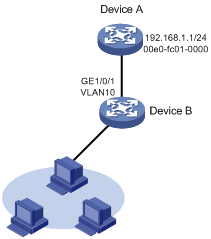
As shown in Figure 3, hosts are connected to Device B. Device B is connected to Device A through interface GigabitEthernet 1/0/1 in VLAN 10.
To ensure secure communications between Device A and Device B, configure a long static ARP entry for Device A on Device B.
Configuration procedure
# Create VLAN 10.
<DeviceB> system-view
[DeviceB] vlan 10
[DeviceB-vlan10] quit
# Add interface GigabitEthernet 1/0/1 to VLAN 10.
[DeviceB] interface gigabitethernet 1/0/1
[DeviceB-GigabitEthernet1/0/1] port access vlan 10
[DeviceB-GigabitEthernet1/0/1] quit
# Create VLAN-interface 10 and configure its IP address.
[DeviceB] interface vlan-interface 10
[DeviceB-vlan-interface10] ip address 192.168.1.2 8
[DeviceB-vlan-interface10] quit
# Configure a long static ARP entry that has IP address 192.168.1.1, MAC address 00e0-fc01-0000, and output interface GigabitEthernet 1/0/1 in VLAN 10.
[DeviceB] arp static 192.168.1.1 00e0-fc01-0000 10 gigabitethernet 1/0/1
Verifying the configuration
# Verify that Device B has a long static ARP entry for Device A.
[DeviceB] display arp static
Type: S-Static D-Dynamic O-Openflow R-Rule M-Multiport I-Invalid
IP address MAC address VLAN/VSI Interface Aging Type
192.168.1.1 00e0-fc01-0000 10 GE1/0/1 -- S
Short static ARP entry configuration example
Network requirements
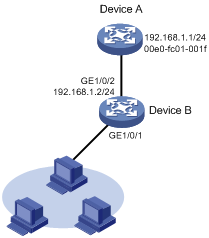
As shown in Figure 4, hosts are connected to Device B. Device B is connected to Device A through interface GigabitEthernet 1/0/2.
To ensure secure communications between Device A and Device B, configure a short static ARP entry for Device A on Device B.
Configuration procedure
# Configure an IP address for GigabitEthernet 1/0/2.
<DeviceB> system-view
[DeviceB] interface gigabitethernet 1/0/2
[DeviceB-GigabitEthernet1/0/2] ip address 192.168.1.2 24
[DeviceB-GigabitEthernet1/0/2] quit
# Configure a short static ARP entry that has IP address 192.168.1.1 and MAC address 00e0-fc01-001f.
[DeviceB] arp static 192.168.1.1 00e0-fc01-001f
Verifying the configuration
# Verify that Device B has a short static ARP entry for Device A
[DeviceB] display arp static
Type: S-Static D-Dynamic O-Openflow R-Rule M-Multiport I-Invalid
IP address MAC address VLAN/VSI Interface Aging Type
192.168.1.1 00e0-fc01-001f N/A -- -- S
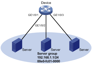
Multiport ARP entry configuration example
Network requirements
As shown in Figure 5, a device connects to three servers through interfaces GigabitEthernet 1/0/1, GigabitEthernet 1/0/2, and GigabitEthernet 1/0/3 in VLAN 10. The servers share the IP address 192.168.1.1/24 and MAC address 00e0-fc01-0000.
Configure a multiport ARP entry so that the device sends IP packets with the destination IP address 192.168.1.1 to the three servers.
Configuration procedure
# Create VLAN 10.
<Device> system-view
[Device] vlan 10
[Device-vlan10] quit
# Add GigabitEthernet 1/0/1, GigabitEthernet 1/0/2, and GigabitEthernet 1/0/3 to VLAN 10.
[Device] interface gigabitethernet 1/0/1
[Device-GigabitEthernet1/0/1] port access vlan 10
[Device-GigabitEthernet1/0/1] quit
[Device] interface gigabitethernet 1/0/2
[Device-GigabitEthernet1/0/2] port access vlan 10
[Device-GigabitEthernet1/0/2] quit
[Device] interface gigabitethernet 1/0/3
[Device-GigabitEthernet1/0/3] port access vlan 10
[Device-GigabitEthernet1/0/3] quit
# Create VLAN-interface 10 and specify its IP address.
[Device] interface vlan-interface 10
[Device-vlan-interface10] ip address 192.168.1.2 24
[Device-vlan-interface10] quit
# Configure a multiport unicast MAC address entry that has MAC address 00e0-fc01-0000, and output interfaces GigabitEthernet 1/0/1, GigabitEthernet 1/0/2, and GigabitEthernet 1/0/3 in VLAN 10.
[Device] mac-address multiport 00e0-fc01-0000 interface gigabitethernet 1/0/1 to gigabitethernet 1/0/3 vlan 10
# Configure a multiport ARP entry with IP address 192.168.1.1 and MAC address 00e0-fc01-0000.
[Device] arp multiport 192.168.1.1 00e0-fc01-0000 10
Verifying the configuration
# Verify that the device has a multiport ARP entry with IP address 192.168.1.1 and MAC address 00e0-fc01-0000.
[Device] display arp
Type: S-Static D-Dynamic O-Openflow R-Rule M-Multiport I-Invalid
IP address MAC address VLAN/VSI Interface Aging Type
192.168.1.1 00e0-fc01-0000 10 -- -- M
Configuring gratuitous ARP
Overview
In a gratuitous ARP packet, the sender IP address and the target IP address are the IP address of the sending device.
A device sends a gratuitous ARP packet for either of the following purposes:
· Determine whether its IP address is already used by another device. If the IP address is already used, the device is informed of the conflict by an ARP reply.
· Inform other devices of a MAC address change.
Gratuitous ARP packet learning
This feature enables a device to create or update ARP entries by using the sender IP and MAC addresses in received gratuitous ARP packets.
When this feature is disabled, the device uses received gratuitous ARP packets to update existing ARP entries only. ARP entries are not created based on the received gratuitous ARP packets, which saves ARP table space.
Periodic sending of gratuitous ARP packets
Enabling periodic sending of gratuitous ARP packets helps downstream devices update ARP entries or MAC entries in a timely manner.
This feature can implement the following functions:
· Prevent gateway spoofing.
Gateway spoofing occurs when an attacker uses the gateway address to send gratuitous ARP packets to the hosts on a network. The traffic destined for the gateway from the hosts is sent to the attacker instead. As a result, the hosts cannot access the external network.
To prevent such gateway spoofing attacks, you can enable the gateway to send gratuitous ARP packets at intervals. Gratuitous ARP packets contain the primary IP address and manually configured secondary IP addresses of the gateway, so hosts can learn correct gateway information.
· Prevent ARP entries from aging out.
If network traffic is heavy or if the host CPU usage is high, received ARP packets can be discarded or are not promptly processed. Eventually, the dynamic ARP entries on the receiving host age out. The traffic between the host and the corresponding devices is interrupted until the host re-creates the ARP entries.
To prevent this problem, you can enable the gateway to send gratuitous ARP packets periodically. Gratuitous ARP packets contain the primary IP address and manually configured secondary IP addresses of the gateway, so the receiving hosts can update ARP entries in a timely manner.
· Prevent the virtual IP address of a VRRP group from being used by a host.
The master router of a VRRP group can periodically send gratuitous ARP packets to the hosts on the local network. The hosts can then update local ARP entries and avoid using the virtual IP address of the VRRP group. The sender MAC address in the gratuitous ARP packet is the virtual MAC address of the virtual router. For more information about VRRP, see High Availability Configuration Guide.
Configuration procedure
When you configure gratuitous ARP, follow these restrictions and guidelines:
· You can enable periodic sending of gratuitous ARP packets on a maximum of 1024 interfaces.
· Periodic sending of gratuitous ARP packets takes effect on an interface only when the following conditions are met:
¡ The data link layer state of the interface is up.
¡ The interface has an IP address.
· If you change the sending interval for gratuitous ARP packets, the configuration takes effect at the next sending interval.
· The sending interval for gratuitous ARP packets might be much longer than the specified sending interval in any of the following circumstances:
¡ This feature is enabled on multiple interfaces.
¡ Each interface is configured with multiple secondary IP addresses.
¡ A small sending interval is configured when the previous two conditions exist.
To configure gratuitous ARP:
|
Step |
Command |
Remarks |
|
1. Enter system view. |
system-view |
N/A |
|
2. Enable learning of gratuitous ARP packets. |
gratuitous-arp-learning enable |
By default, learning of gratuitous ARP packets is enabled. |
|
3. Enable the device to send gratuitous ARP packets upon receiving ARP requests whose sender IP address belongs to a different subnet. |
gratuitous-arp-sending enable |
By default, a device does not send gratuitous ARP packets upon receiving ARP requests whose sender IP address belongs to a different subnet. |
|
4. Enter interface view. |
interface interface-type interface-number |
N/A |
|
5. Enable periodic sending of gratuitous ARP packets. |
arp send-gratuitous-arp [ interval interval ] |
By default, periodic sending of gratuitous ARP packets is disabled. |
Enabling IP conflict notification
By default, if the sender IP address of an ARP packet is being used by the receiving device, the receiving device sends a gratuitous ARP request. It also displays an error message after it receives an ARP reply about the conflict.
You can use this command to enable the device to display error messages before sending a gratuitous ARP reply or request for conflict confirmation.
To enable IP conflict notification:
|
Step |
Command |
Remarks |
|
1. Enter system view. |
system-view |
N/A |
|
2. Enable IP conflict notification. |
arp ip-conflict log prompt |
By default, IP conflict notification is disabled. |
Configuring gratuitous ARP packet retransmission for the device MAC address change
The device sends a gratuitous ARP packet to inform other devices of its MAC address change. However, the other devices might fail to receive the packet because the device sends the gratuitous ARP packet only once by default. Configure the gratuitous ARP packet retransmission feature to ensure that the other devices can receive the packet.
To configure gratuitous ARP packet retransmission for the device MAC address change:
|
Step |
Command |
Remarks |
|
1. Enter system view. |
system-view |
N/A |
|
2. Set the times and the interval for retransmitting a gratuitous ARP packet for the device MAC address change. |
gratuitous-arp mac-change retransmit times interval seconds |
By default, the device sends a gratuitous packet to inform its MAC address change only once. |
Configuring proxy ARP
Proxy ARP enables a device on one network to answer ARP requests for an IP address on another network. With proxy ARP, hosts on different broadcast domains can communicate with each other as they would on the same broadcast domain.
Proxy ARP includes common proxy ARP and local proxy ARP.
· Common proxy ARP—Allows communication between hosts that connect to different Layer 3 interfaces and reside in different broadcast domains.
· Local proxy ARP—Allows communication between hosts that connect to the same Layer 3 interface and reside in different broadcast domains.
Enabling common proxy ARP
|
Step |
Command |
Remarks |
|
1. Enter system view. |
system-view |
N/A |
|
2. Enter interface view. |
interface interface-type interface-number |
The following interface types are supported: · VLAN interface. · Layer 3 Ethernet interface. · Layer 3 Ethernet subinterface. · Layer 3 aggregate interface. · Layer 3 aggregate subinterface. |
|
3. Enable common proxy ARP. |
proxy-arp enable |
By default, common proxy ARP is disabled. |
Enabling local proxy ARP
|
Step |
Command |
Remarks |
|
1. Enter system view. |
system-view |
N/A |
|
2. Enter interface view. |
interface interface-type interface-number |
The following interface types are supported: · VLAN interface. · Layer 3 Ethernet interface. · Layer 3 Ethernet subinterface. · Layer 3 aggregate interface. · Layer 3 aggregate subinterface. |
|
3. Enable local proxy ARP. |
local-proxy-arp enable [ ip-range start-ip-address to end-ip-address ] |
By default, local proxy ARP is disabled. |
Displaying proxy ARP
Execute display commands in any view.
|
Task |
Command |
|
Display common proxy ARP status. |
display proxy-arp [ interface interface-type interface-number ] |
|
Display local proxy ARP status. |
display local-proxy-arp [ interface interface-type interface-number ] |
Common proxy ARP configuration example
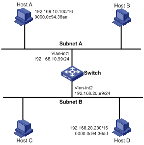
Network requirements
As shown in Figure 6, Host A and Host D have the same IP prefix and mask, but they are located on different subnets separated by the switch. Host A belongs to VLAN 1, and Host D belongs to VLAN 2. No default gateway is configured on Host A and Host D.
Configure common proxy ARP on the switch to enable communication between the two hosts.
Configuration procedure
# Create VLAN 2.
<Switch> system-view
[Switch] vlan 2
[Switch-vlan2] quit
# Configure the IP address of VLAN-interface 1.
[Switch] interface vlan-interface 1
[Switch-Vlan-interface1] ip address 192.168.10.99 255.255.255.0
# Enable common proxy ARP on VLAN-interface 1.
[Switch-Vlan-interface1] proxy-arp enable
[Switch-Vlan-interface1] quit
# Configure the IP address of VLAN-interface 2.
[Switch] interface vlan-interface 2
[Switch-Vlan-interface2] ip address 192.168.20.99 255.255.255.0
# Enable common proxy ARP on VLAN-interface 2.
[Switch-Vlan-interface2] proxy-arp enable
Verifying the configuration
# Verify that Host A and Host D can ping each other.
Configuring ARP snooping
ARP snooping is used in Layer 2 switching networks. It creates ARP snooping entries by using information in ARP packets. ARP fast-reply and manual-mode MFF can use the ARP snooping entries. For more information about MFF, see Security Configuration Guide.
If you enable ARP snooping for a VLAN or VXLAN, ARP packets received in the VLAN or VXLAN are redirected to the CPU. For the VLAN, the CPU uses the sender IP and MAC addresses of the ARP packets, and receiving VLAN and port to create ARP snooping entries. For the VXLAN, the CPU uses the sender IP and MAC addresses of the ARP packets, VSI name, and link ID to create ARP snooping entries. For more information about VXLAN, see VXLAN Configuration Guide.
The aging timer and valid period of an ARP snooping entry are 25 minutes and 15 minutes. If an ARP snooping entry is not updated in 12 minutes, the device sends an ARP request. The ARP request uses the IP address of the entry as the target IP address. If an ARP snooping entry is not updated in 15 minutes, it becomes invalid and cannot be used. After that, if an ARP packet matching the entry is received, the entry becomes valid, and its aging timer restarts. If the aging timer of an ARP snooping entry expires, the entry is removed.
An attack occurs if an ARP packet has the same sender IP address as a valid ARP snooping entry but a different sender MAC address. The ARP snooping entry becomes invalid, and it is removed in 1 minute.
Configuration procedure
To enable ARP snooping for a VLAN:
|
Step |
Command |
Remarks |
|
1. Enter system view. |
system-view |
N/A |
|
2. Enter VLAN view. |
vlan vlan-id |
N/A |
|
3. Enable ARP snooping for the VLAN. |
arp snooping enable |
By default, ARP snooping is disabled for a VLAN. |
To enable ARP snooping for a VSI:
|
Step |
Command |
Remarks |
|
1. Enter system view. |
system-view |
N/A |
|
2. Enter VSI view. |
vsi vsi-name |
N/A |
|
3. Enable ARP snooping for the VSI. |
arp snooping enable |
By default, ARP snooping is disabled for a VSI. |
Displaying and maintaining ARP snooping
Execute display commands in any view and reset commands in user view.
|
Task |
Command |
|
(In standalone mode.) Display ARP snooping entries. |
display arp snooping { vlan [ vlan-id ] ]| vsi [vsi-name ] } [ slot slot-number ] [ count ] display arp snooping vlan ip ip-address [ slot slot-number ] |
|
(In IRF mode.) Display ARP snooping entries. |
display arp snooping { vlan [ vlan-id ] ] | vsi [vsi-name ] } [ chassis chassis-number slot slot-number ] [ count ] display arp snooping vlan ip ip-address [ chassis chassis-number slot slot-number ] |
|
Remove ARP snooping entries. |
reset arp snooping { vlan [ vlan-id ] | vsi [ vsi-name ] } reset arp snooping vlan ip ip-address |
Configuring ARP fast-reply
Overview
ARP fast-reply enables a device to directly answer ARP requests according to DHCP snooping entries or ARP snooping entries. ARP fast-reply functions in a VLAN. For information about DHCP snooping, see "Configuring DHCP snooping."
If the target IP address of a received ARP request is the IP address of the VLAN interface, the device delivers the request to the ARP module. If not, the device takes the following steps to process the packet:
1. Search the DHCP snooping table for a match by using the target IP address.
2. If a match is found, whether the device returns a reply depends on the interface in the matching entry.
¡ If the interface is the Ethernet interface that received the ARP request, the device does not return any reply.
¡ If the interface is an Ethernet interface other than the receiving interface, the device returns a reply according to the matching entry.
3. If no matching DHCP snooping entry is found and ARP snooping is enabled, the device searches the ARP snooping table.
¡ If the interface in the matching entry is the Ethernet interface that received the ARP request, the device does not return any reply.
¡ If the interface is an Ethernet interface other than the receiving interface, the device returns a reply according to the ARP snooping entry.
4. If no match is found in both tables, the ARP request is forwarded to other interfaces except the receiving interface in the VLAN, or delivered to other modules.
Configuration procedure
To improve the availability of ARP fast-reply, enable ARP snooping at the same time.
To configure ARP fast-reply:
|
Step |
Command |
Remarks |
|
1. Enter system view. |
system-view |
N/A |
|
2. Enter VLAN view. |
vlan vlan-id |
N/A |
|
3. Enable ARP fast-reply. |
arp fast-reply enable |
By default, ARP fast-reply is disabled. |
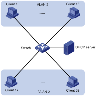
ARP fast-reply configuration example
Network requirements
As shown in Figure 7, all clients are in VLAN 2, and access the network through the switch. They have obtained IP addresses through DHCP.
Enable ARP snooping and ARP fast-reply for VLAN 2. The switch directly returns an ARP reply without broadcasting received ARP requests in the VLAN.
Configuration procedure
# Enable ARP snooping for VLAN 2 on the switch.
<Switch> system-view
[Switch] vlan 2
[Switch-vlan2] arp snooping enable
# Enable ARP fast-reply for VLAN 2 on the switch.
[Switch-vlan2] arp fast-reply enable
[Switch-vlan2] quit
Configuring ARP proxy forwarding
With this feature enabled on an interface, the device does not issue static ARP entries that use the interface as the output interface and dynamic ARP entries to principal ARP/ND service modules. When a principal ARP/ND service module receives a packet whose destination IP address resides on the same subnet as the interface, it delivers the packet to a proxy ARP/ND service module for forwarding.
Principal ARP/ND service modules include service modules that operate in the adj-proxy-low proxy mode and service modules that do not operate in any proxy mode.
Proxy ARP/ND service modules include service modules that operate in the adj-proxy-high proxy mode.
For more information about proxy modes, see device management in Fundamentals Configuration Guide.
When you configure ARP proxy forwarding, follow these restrictions and guidelines:
· This feature is supported only when both a principal service module and a proxy service module are present on the device.
· This feature cannot operate with uRPF. For information about uRPF, see Security Configuration Guide.
· In an MPLS L3VPN network, a PE's interfaces bound to VPN instances do not support ARP proxy forwarding. For information about PE devices and VPN instances, see MPLS Configuration Guide.
To enable ARP proxy forwarding:
|
Step |
Command |
Remarks |
|
1. Enter system view. |
system-view |
N/A |
|
2. Create a VLAN interface and enter its view. |
interface vlan-interface vlan-interface-id |
You cannot create a VLAN interface for a nonexistent VLAN. If the VLAN interface exists, you directly enter its view. |
|
3. Enable ARP proxy forwarding. |
arp proxy-forwarding |
By default, ARP proxy forwarding is disabled. |
Configuring ARP direct route advertisement
Overview
Mechanism of ARP direct route advertisement
The ARP direct route advertisement feature advertises host routes instead of advertising the network route.
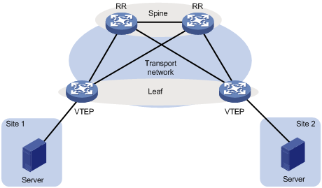
Cooperation with BGP
As shown in Figure 8, this feature can cooperate with BGP in an EVPN network. The Layer 3 Ethernet interfaces that directly connect a leaf node and a spine node borrow IP addresses with the subnet mask 255.255.255.255, for example, from loopback interfaces. For communication, the leaf node and the spine node learn the ARP entry of each other through LLDP.
Because the IP addresses of the interfaces that directly connect the spine node and the leaf node belong to different subnets, one node does not have the direct route to the other node. If BGP is used to transmit underlay network routes, BGP cannot perform correct route recursion. To resolve this problem, enable ARP direct route advertisement on the Layer 3 Ethernet interfaces that directly connect the spine node and the leaf node. One node generates a direct route to the other node and BGP can perform correct route recursion.
For information about EVPN, see EVPN Configuration Guide. For information about LLDP, see Layer 2—LAN Switching Configuration Guide. For information about BGP, see Layer 3—IP Routing Configuration Guide.
Figure 8 ARP direct route with BGP
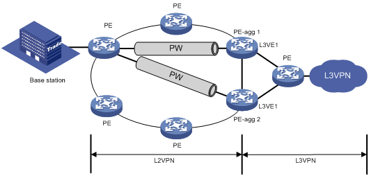
Application in L2VPN access to L3VPN networks
As shown in Figure 9, the ARP direct route feature is configured on PE-aggs to advertise host routes to the connected PEs in the L3VPN.
The PE in the L3VPN has ECMP routes destined to a base station in the L2VPN. Traffic from the PE in the L3VPN to the base station can be load shared by PE-agg 1 and PE-agg 2. If PE-agg 1 fails, the PE uses the host route through PE-agg 2 to forward traffic.
For information about L2VPN access to L3VPN, see MPLS Configuration Guide.
Enabling ARP direct route advertisement
|
Step |
Command |
Remarks |
|
1. Enter system view. |
system-view |
N/A |
|
2. Enter interface view. |
interface interface-type interface-number |
N/A |
|
3. Enable the ARP direct route advertisement feature. |
arp route-direct advertise |
By default, the ARP direct route advertisement feature is disabled. |