- Table of Contents
-
- 04-Layer 2 - LAN Switching Configuration Guide
- 00-Preface
- 01-MAC address table configuration
- 02-Ethernet link aggregation configuration
- 03-DRNI configuration
- 04-Port isolation configuration
- 05-VLAN configuration
- 06-MVRP configuration
- 07-QinQ configuration
- 08-VLAN mapping configuration
- 09-Loop detection configuration
- 10-Spanning tree configuration
- 11-LLDP configuration
- 12-L2PT configuration
- 13-Service loopback group configuration
- Related Documents
-
| Title | Size | Download |
|---|---|---|
| 12-L2PT configuration | 139.53 KB |
L2PT restrictions and guidelines
Setting the destination multicast MAC address for tunneled packets
Displaying and maintaining L2PT
Configuring L2PT
Overview
Layer 2 Protocol Tunneling (L2PT) can transparently send Layer 2 protocol packets from geographically dispersed customer networks across a service provider network or drop them.
Background
Dedicated lines are used in a service provider network to build user-specific Layer 2 networks. As a result, a customer network contains sites located at different sides of the service provider network.
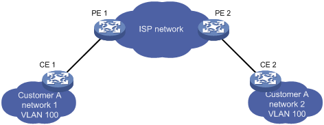
As shown in Figure 1, Customer A's network is divided into network 1 and network 2, which are connected by the service provider network. For Customer A's network to implement Layer 2 protocol calculations, the Layer 2 protocol packets must be transmitted across the service provider network.
Upon receiving a Layer 2 protocol packet, the PEs cannot determine whether the packet is from the customer network or the service provider network. They must deliver the packet to the CPU for processing. In this case, the Layer 2 protocol calculation in Customer A's network is mixed with the Layer 2 protocol calculation in the service provider network. Neither the customer network nor the service provider network can implement independent Layer 2 protocol calculations.
Figure 1 L2PT application scenarios
L2PT is introduced to resolve the problem. L2PT provides the following functions:
· Multicasts Layer 2 protocol packets from a customer network in a VLAN. Dispersed customer networks can complete an independent Layer 2 protocol calculation, which is transparent to the service provider network.
· Isolates Layer 2 protocol packets from different customer networks through different VLANs.
H3C devices support L2PT for the following protocols:
· CDP.
· DLDP.
· EOAM.
· GVRP.
· LACP.
· LLDP.
· MVRP.
· PAgP.
· PVST.
· STP (including STP, RSTP, and MSTP).
· UDLD.
· VTP.
L2PT operating mechanism
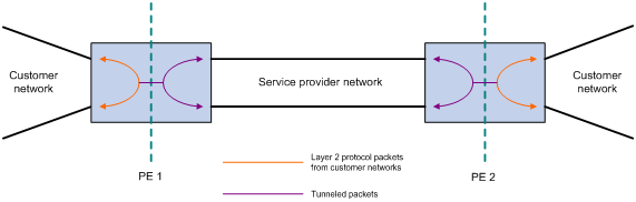
As shown in Figure 2, L2PT operates as follows:
· When a port of PE 1 receives a Layer 2 protocol packet from the customer network in a VLAN, it performs the following operations:
¡ Multicasts the packet out of all customer-facing ports in the VLAN except the receiving port.
¡ Changes the packet's destination multicast MAC address to a specified multicast address, and multicasts it out of all ISP-facing ports in the VLAN. The modified packet is called the tunneled packet.
· When a port of PE 2 in the VLAN receives the tunneled packet from the service provider network, it performs the following operations:
¡ Multicasts the packet out of all ISP-facing ports in the VLAN except the receiving port.
¡ Changes the destination multicast MAC address to the original MAC address, and multicasts the packet out of all customer-facing ports in the VLAN.
Figure 2 L2PT operating mechanism
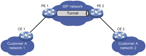
For example, as shown in Figure 3, PE 1 receives an STP packet (BPDU) from network 1 to network 2. CEs are the edge devices on the customer network, and PEs are the edge devices on the service provider network. L2PT processes the packet as follows:
1. PE 1 performs the following operations:
a. Changes the packet's destination multicast MAC address 0180-c200-0000 to a specified multicast MAC address (010f-e200-0003 by default) for the BPDU.
b. Sends the tunneled packet out of all ISP-facing ports in the packet's VLAN.
2. Upon receiving the tunneled packet, PE 2 decapsulates the packet and sends the BPDU to CE 2.
Through L2PT, both the ISP network and Customer A's network can perform independent spanning tree calculations.
L2PT restrictions and guidelines
Configure L2PT only on PE devices.
L2PT configuration task list
|
Tasks at a glance |
|
(Required.) Enabling L2PT |
|
(Optional.) Setting the destination multicast MAC address for tunneled packets |
Enabling L2PT
Restrictions and guidelines
· To enable L2PT for a Layer 2 protocol on a port, perform the following tasks:
¡ Enable the protocol on the connected CE, and disable the protocol on the port.
¡ Disable the protocol (for example, STP) on the PE ports connecting to an aggregate interface on a CE when the following conditions exists:
- The protocol is running on the aggregate interface on the CE.
- The aggregate interface on the CE connects to an L2PT-enabled port on the PE.
¡ Enable L2PT on ports connected to a customer network. If you enable L2PT on ports connected to the service provider network, L2PT determines that the ports are connected to a customer network.
¡ Make sure the VLAN tags of Layer 2 protocol packets are not changed or deleted for the tunneled packets to be transmitted correctly across the service provider network.
· L2PT for LLDP supports LLDP packets from only nearest bridge agents.
· You can enable L2PT on a member port of a Layer 2 aggregation group, but the configuration does not take effect.
· Do not enable L2PT on a port that is going to join a service loopback group.
· LACP and EOAM require point-to-point transmission. If you enable L2PT for LACP or EOAM, L2PT multicasts LACP or EOAM packets out of customer-facing ports. As a result, the transmission between two CEs is not point-to-point. To ensure point-to-point transmission for the LACP or EOAM packets, you must configure other features (for example, VLAN).
Enabling L2PT for a protocol
|
Step |
Command |
Remarks |
|
1. Enter system view. |
system-view |
N/A |
|
2. Enter interface view. |
· Enter Layer 2 Ethernet interface view: · Enter Layer 2 aggregate interface view: |
N/A |
|
3. Enable L2PT for a protocol. |
· In Layer 2 Ethernet interface view: · In Layer 2 aggregate interface view: |
By default, L2PT is disabled for all protocols. |
Setting the destination multicast MAC address for tunneled packets
When you set the destination multicast MAC address for tunneled packets, follow these restrictions and guidelines:
· For tunneled packets to be recognized, set the same destination multicast MAC addresses on PEs that are connected to the same customer network.
· As a best practice, set different destination multicast MAC addresses on PEs connected to different customer networks. It prevents L2PT from sending packets of a customer network to another customer network.
To set the destination multicast MAC address for tunneled packets:
|
Step |
Command |
Remarks |
|
1. Enter system view. |
system-view |
N/A |
|
2. Set the destination multicast MAC address for tunneled packets. |
l2protocol tunnel-dmac mac-address |
The available multicast MAC addresses are 010f-e200-0003, 0100-0ccd-cdd0, 0100-0ccd-cdd1, and 0100-0ccd-cdd2. By default, 010f-e200-0003 is used for tunneled packets. |
Displaying and maintaining L2PT
Execute display commands in any view and reset commands in user view.
|
Task |
Command |
|
Display L2PT statistics. |
display l2protocol statistics [ interface interface-type interface-number ] |
|
Clear L2PT statistics. |
reset l2protocol statistics [ interface interface-type interface-number ] |
L2PT configuration examples
Configuring L2PT for STP
Network requirements
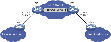
As shown in Figure 4, the MAC addresses of CE 1 and CE 2 are 00e0-fc02-5800 and 00e0-fc02-5802, respectively. MSTP is enabled in Customer A's network, and default MSTP settings are used.
Perform the following tasks on the PEs:
· Configure the ports that connect to CEs as access ports, and configure the ports in the service provider network as trunk ports. Configure ports in the service provider network to allow packets from any VLAN to pass.
· Enable L2PT for STP to enable Customer A's network to implement independent spanning tree calculation across the service provider network.
· Set the destination multicast MAC address to 0100-0ccd-cdd0 for tunneled packets.
Configuration procedures
1. Configure PE 1:
# Set the destination multicast address to 0100-0ccd-cdd0 for tunneled packets.
<PE1> system-view
[PE1] l2protocol tunnel-dmac 0100-0ccd-cdd0
# Create VLAN 2.
[PE1] vlan 2
[PE1-vlan2] quit
# Configure GigabitEthernet 1/0/1 as an access port and assign the port to VLAN 2.
[PE1] interface gigabitethernet 1/0/1
[PE1-GigabitEthernet1/0/1] port access vlan 2
# Disable STP and enable L2PT for STP on GigabitEthernet 1/0/1.
[PE1-GigabitEthernet1/0/1] undo stp enable
[PE1-GigabitEthernet1/0/1] l2protocol stp tunnel dot1q
[PE1-GigabitEthernet1/0/1] quit
# Configure GigabitEthernet 1/0/2 connected to the service provider network as a trunk port, and assign the port to all VLANs.
[PE1] interface gigabitethernet 1/0/2
[PE1-GigabitEthernet1/0/2] port link-type trunk
[PE1-GigabitEthernet1/0/2] port trunk permit vlan all
[PE1-GigabitEthernet1/0/2] quit
2. Configure PE 2 in the same way PE 1 is configured. (Details not shown.)
Verifying the configuration
# Verify that the root bridge of Customer A's network is CE 1.
<CE2> display stp root
MST ID Root Bridge ID ExtPathCost IntPathCost Root Port
0 32768.00e0-fc02-5800 0 0
# Verify that the root bridge of the service provider network is not CE 1.
[PE1] display stp root
MST ID Root Bridge ID ExtPathCost IntPathCost Root Port
0 32768.0cda-41c5-ba50 0 0
Configuring L2PT for LACP
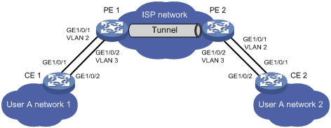
Network requirements
As shown in Figure 5, the MAC addresses of CE 1 and CE 2 are 0001-0000-0000 and 0004-0000-0000, respectively.
Perform the following tasks:
· Configure Ethernet link aggregation on CE 1 and CE 2.
· Configure GigabitEthernet 1/0/1 and GigabitEthernet 1/0/2 on CE 1 to form aggregate links with GigabitEthernet 1/0/1 and GigabitEthernet 1/0/2 on CE 2, respectively.
· Enable L2PT for LACP to enable CE 1 and CE 2 to implement Ethernet link aggregation across the service provider network.
Requirements analysis
To meet the network requirements, perform the following tasks:
· For Ethernet link aggregation to operate correctly, configure VLANs on the PEs to ensure point-to-point transmission between CE 1 and CE 2 in an aggregation group.
¡ Set the PVIDs to VLAN 2 and VLAN 3 for GigabitEthernet 1/0/1 and GigabitEthernet 1/0/2 on PE 1, respectively.
¡ Configure PE 2 in the same way PE 1 is configured.
¡ Configure ports that connect to the CEs as trunk ports.
· To retain the VLAN tag of the customer network, enable QinQ on GigabitEthernet 1/0/1 and GigabitEthernet 1/0/2 on both PE 1 and PE 2.
· For packets from any VLAN to be transmitted, configure all ports in the service provider network as trunk ports.
Configuration procedures
1. Configure CE 1:
# Configure Layer 2 aggregation group Bridge-Aggregation 1 to operate in dynamic aggregation mode.
<CE1> system-view
[CE1] interface bridge-aggregation 1
[CE1-Bridge-Aggregation1] port link-type access
[CE1-Bridge-Aggregation1] link-aggregation mode dynamic
[CE1-Bridge-Aggregation1] quit
# Assign GigabitEthernet 1/0/1 and GigabitEthernet 1/0/2 to Bridge-Aggregation 1.
[CE1] interface gigabitethernet 1/0/1
[CE1-GigabitEthernet1/0/1] port link-aggregation group 1
[CE1-GigabitEthernet1/0/1] quit
[CE1] interface gigabitethernet 1/0/2
[CE1-GigabitEthernet1/0/2] port link-aggregation group 1
[CE1-GigabitEthernet1/0/2] quit
2. Configure CE 2 in the same way CE 1 is configured. (Details not shown.)
3. Configure PE 1:
# Create VLANs 2 and 3.
<PE1> system-view
[PE1] vlan 2
[PE1-vlan2] quit
[PE1] vlan 3
[PE1-vlan3] quit
# Configure GigabitEthernet 1/0/1 as a trunk port, assign the port to VLAN 2, and set the PVID to VLAN 2.
[PE1] interface gigabitethernet 1/0/1
[PE1-GigabitEthernet1/0/1] port link-mode bridge
[PE1-GigabitEthernet1/0/1] port link-type trunk
[PE1-GigabitEthernet1/0/1] port trunk permit vlan 2
[PE1-GigabitEthernet1/0/1] port trunk pvid vlan 2
# Enable QinQ on GigabitEthernet 1/0/1.
[PE1-GigabitEthernet1/0/1] qinq enable
# Enable L2PT for LACP on GigabitEthernet 1/0/1.
[PE1-GigabitEthernet1/0/1] l2protocol lacp tunnel dot1q
[PE1-GigabitEthernet1/0/1] quit
# Configure GigabitEthernet 1/0/2 as a trunk port, assign the port to VLAN 3, and set the PVID to VLAN 3.
[PE1] interface gigabitethernet 1/0/2
[PE1-GigabitEthernet1/0/2] port link-mode bridge
[PE1-GigabitEthernet1/0/2] port link-type trunk
[PE1-GigabitEthernet1/0/2] port trunk permit vlan 3
[PE1-GigabitEthernet1/0/2] port trunk pvid vlan 3
# Enable QinQ on GigabitEthernet 1/0/2.
[PE1-GigabitEthernet1/0/2] qinq enable
# Enable L2PT for LACP on GigabitEthernet 1/0/2.
[PE1-GigabitEthernet1/0/2] l2protocol lacp tunnel dot1q
[PE1-GigabitEthernet1/0/2] quit
4. Configure PE 2 in the same way PE 1 is configured. (Details not shown.)
Verifying the configuration
# Verify that CE 1 and CE 2 have completed Ethernet link aggregation successfully.
[CE1] display link-aggregation member-port
Flags: A -- LACP_Activity, B -- LACP_Timeout, C -- Aggregation,
D -- Synchronization, E -- Collecting, F -- Distributing,
G -- Defaulted, H -- Expired
GigabitEthernet1/0/1:
Aggregate Interface: Bridge-Aggregation1
Local:
Port Number: 3
Port Priority: 32768
Oper-Key: 1
Flag: {ACDEF}
Remote:
System ID: 0x8000, 0004-0000-0000
Port Number: 3
Port Priority: 32768
Oper-Key: 1
Flag: {ACDEF}
Received LACP Packets: 23 packet(s)
Illegal: 0 packet(s)
Sent LACP Packets: 26 packet(s)
GigabitEthernet1/0/2:
Aggregate Interface: Bridge-Aggregation1
Local:
Port Number: 4
Port Priority: 32768
Oper-Key: 1
Flag: {ACDEF}
Remote:
System ID: 0x8000, 0004-0000-0000
Port Number: 4
Port Priority: 32768
Oper-Key: 1
Flag: {ACDEF}
Received LACP Packets: 10 packet(s)
Illegal: 0 packet(s)
Sent LACP Packets: 13 packet(s)
[CE2] display link-aggregation member-port
Flags: A -- LACP_Activity, B -- LACP_Timeout, C -- Aggregation,
D -- Synchronization, E -- Collecting, F -- Distributing,
G -- Defaulted, H -- Expired
GigabitEthernet1/0/1:
Aggregate Interface: Bridge-Aggregation1
Local:
Port Number: 3
Port Priority: 32768
Oper-Key: 1
Flag: {ACDEF}
Remote:
System ID: 0x8000, 0001-0000-0000
Port Number: 3
Port Priority: 32768
Oper-Key: 1
Flag: {ACDEF}
Received LACP Packets: 23 packet(s)
Illegal: 0 packet(s)
Sent LACP Packets: 26 packet(s)
GigabitEthernet1/0/2:
Aggregate Interface: Bridge-Aggregation1
Local:
Port Number: 4
Port Priority: 32768
Oper-Key: 1
Flag: {ACDEF}
Remote:
System ID: 0x8000, 0001-0000-0000
Port Number: 4
Port Priority: 32768
Oper-Key: 1
Flag: {ACDEF}
Received LACP Packets: 10 packet(s)
Illegal: 0 packet(s)
Sent LACP Packets: 13 packet(s)