- Table of Contents
-
- 04-Layer 2 - LAN Switching Configuration Guide
- 00-Preface
- 01-MAC address table configuration
- 02-Ethernet link aggregation configuration
- 03-DRNI configuration
- 04-Port isolation configuration
- 05-VLAN configuration
- 06-MVRP configuration
- 07-QinQ configuration
- 08-VLAN mapping configuration
- 09-Loop detection configuration
- 10-Spanning tree configuration
- 11-LLDP configuration
- 12-L2PT configuration
- 13-Service loopback group configuration
- Related Documents
-
| Title | Size | Download |
|---|---|---|
| 04-Port isolation configuration | 54.25 KB |
Restrictions and guidelines: Port isolation configuration
Assigning a port to an isolation group
Displaying and maintaining port isolation
Port isolation configuration example
Configuring port isolation
The port isolation feature isolates Layer 2 traffic for data privacy and security without using VLANs.
Ports in an isolation group cannot communicate with each other. However, they can communicate with ports outside the isolation group.
Restrictions and guidelines: Port isolation configuration
Follow these guidelines when you configure port isolation:
· When selective flood is enabled for a VXLAN VSI, port isolation does not affect selective flood if you assign a site-facing interface of the VSI to an isolation group. An AC on the interface still floods frames that match selective flood entries to all site-facing interfaces in the VXLAN, including the interfaces in the same isolation group.
To enable selective flood for a MAC address in a VXLAN VSI, use the selective-flooding mac-address command. For more information, see VXLAN Configuration Guide.
· In an isolation group, a port associated with a VXLAN AC can still act as a trusted port to forward DHCP packets to the other ports in the isolation group.
To configure a port as a trusted port in a DHCP snooping-enabled network, use the dhcp snooping trust command. For more information, see DHCP snooping configuration in Layer 3—IP Services Configuration Guide.
Assigning a port to an isolation group
The device supports multiple isolation groups, which can be configured manually. The number of ports assigned to an isolation group is not limited.
To assign a port to an isolation group:
|
Step |
Command |
Remarks |
|
1. Enter system view. |
system-view |
N/A |
|
1. Create an isolation group. |
port-isolate group group-id |
By default, no isolation groups exist. |
|
2. Enter interface view. |
· Enter Layer 2 Ethernet interface view: · Enter Layer 2 aggregate interface view: |
· The configuration in Layer 2 Ethernet interface view applies only to the interface. · The configuration in Layer 2 aggregate interface view applies to the Layer 2 aggregate interface and its aggregation member ports. If the device fails to apply the configuration to the aggregate interface, it does not assign any aggregation member port to the isolation group. If the failure occurs on an aggregation member port, the device skips the port and continues to assign other aggregation member ports to the isolation group. |
|
3. Assign the port to the isolation group. |
port-isolate enable group group-id |
By default, the port is not in any isolation group. You can assign a port to only one isolation group. If you execute the port-isolate enable group command multiple times, the most recent configuration takes effect. |
Displaying and maintaining port isolation
Execute display commands in any view.
|
Task |
Command |
|
Display isolation group information. |
display port-isolate group [ group-id ] |
Port isolation configuration example
Network requirements
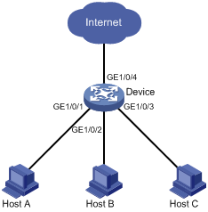
As shown in Figure 1:
· LAN users Host A, Host B, and Host C are connected to GigabitEthernet 1/0/1, GigabitEthernet 1/0/2, and GigabitEthernet 1/0/3 on the device, respectively.
· The device connects to the Internet through GigabitEthernet 1/0/4.
Configure the device to provide Internet access for the hosts, and isolate them from one another at Layer 2.
Configuration procedure
# Create isolation group 2.
<Device> system-view
[Device] port-isolate group 2
[Device-port-isolate-group2] quit
# Assign GigabitEthernet 1/0/1, GigabitEthernet 1/0/2, and GigabitEthernet 1/0/3 to isolation group 2.
[Device] interface gigabitethernet 1/0/1
[Device-GigabitEthernet1/0/1] port-isolate enable group 2
[Device-GigabitEthernet1/0/1] quit
[Device] interface gigabitethernet 1/0/2
[Device-GigabitEthernet1/0/2] port-isolate enable group 2
[Device-GigabitEthernet1/0/2] quit
[Device] interface gigabitethernet 1/0/3
[Device-GigabitEthernet1/0/3] port-isolate enable group 2
[Device-GigabitEthernet1/0/3] quit
Verifying the configuration
# Display information about isolation group 2.
[Device] display port-isolate group 2
Port isolation group information:
Group ID: 2
Group members:
GigabitEthernet1/0/1 GigabitEthernet1/0/2 GigabitEthernet1/0/3
Community VLAN ID: None
The output shows that GigabitEthernet 1/0/1, GigabitEthernet 1/0/2, and GigabitEthernet 1/0/3 are assigned to isolation group 2. As a result, Host A, Host B, and Host C are isolated from one another at layer 2.