- Table of Contents
- Related Documents
-
| Title | Size | Download |
|---|---|---|
| 01-Text | 4.20 MB |
Contents
Chassis views and technical specifications
Examining the installation site
Attaching the slide rails to the rack
Installing the switch in the rack
Accessing the switch for the first time
This installation quick start provides basic instructions for installing an S7508E-X switch. For more information about the technical specifications, see H3C S7508E-X Switch Installation Guide.
|
|
NOTE: The figures in this installation quick start are for illustration only. |
Chassis views and technical specifications
Chassis views
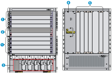
Figure 1 Front and rear panels
|
(1) LPU slots |
(2) MPU slots |
|
(3) Power module slots |
(4) Fan tray slot |
|
(5) Switching fabric module slots |
|
Technical specifications
Table 1 Switch dimensions
|
Height |
Width |
Depth |
|
|
S7508E-X |
620 mm (24.41 in) (14 RU) |
440 mm (17.32 in) |
660 mm (25.98 in) |
Table 2 Power module specifications
|
Item |
LSUM1AC1200 specifications |
LSUM1AC2500 specifications |
LSUM1DC2400 specifications |
|
Rated input voltage range |
100 VAC to 240 VAC @ 50/60 Hz |
100 VAC to 240 VAC @ 50/60 Hz |
–48 VDC to –60 VDC |
|
Rated output voltage |
12 VDC |
12 VDC |
12 VDC |
|
Maximum input current |
16 A |
16 A |
60 A |
|
Maximum output current |
100 A |
· 100 A (110 VAC) · 208 A (220 VAC) |
200 A |
|
Maximum output power |
1200 W |
· 1200 W (110 VAC) · 2500 W (220 VAC) |
2400 W |
|
Quantity |
1 to 6 |
||
Safety recommendations
To avoid equipment damage or bodily injury caused by improper use, read the following safety recommendations before installation. Note that the recommendations do not cover every possible hazardous condition.
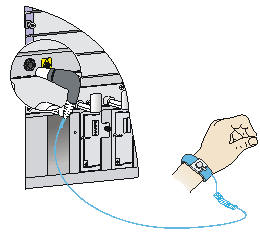
· To prevent ESD damage, always wear an ESD wrist strap and make sure it is reliably grounded before you touch the switch, cards, or PCB.
· Do not install the switch, FRUs, or power cords when the switch is powered on.
· To avoid equipment damage or bodily injury, make sure the switch is reliably grounded before powering on the switch.
· To ensure good ventilation, install a blank filler panel in an unused slot.
Figure 2 Attaching an ESD wrist strap
Examining the installation site
The switch can only be used indoors. To make sure the switch operates correctly and prolong its service lifetime, the installation site must meet the requirements for load-bearing, temperature, humidity, cleanness, EMI, grounding power module, ventilation, and space. For more information, see H3C S7508E-X Switch Installation Guide.
If you are to install the switch in an enclosed rack, make sure the rack meets the following requirements:
· A minimum of 100 mm (3.94 in) distance between the front rack posts and the front door for accommodating the cable management brackets.
· A minimum of 710 mm (27.95 in) distance between the front rack posts and the rear door for accommodating the chassis and card handles.
Installing the switch
Attaching the slide rails to the rack
1. Read the signs on the slide rails to identify the left and right slide rails and their front ends, as shown in Table 3.
Table 3 Description for signs on the slide rails
|
Sign |
Meaning |
Remarks |
|
F/L |
Front end of the left slide rail |
Mount this end to the front left rack post. |
|
F/R |
Front end of the right slide rail |
Mount this end to the front right rack post. |
2. Mark the installation position on the rack for the slide rails:
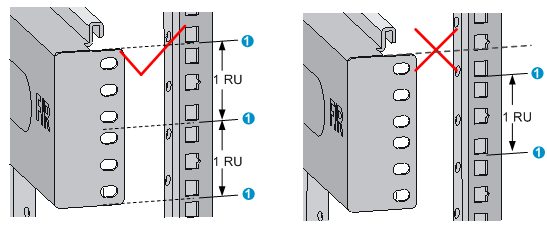
a. Make sure the top flange of a slide rail aligns with the middle of the narrower metal area between holes in a rack post, as shown in Figure 3.
b. Each rack post requires six screws to attach the slide rail. Mark only the uppermost and lowermost holes.
c. Mark the square holes at the same height on the other three rack posts.
Figure 3 Determining the cage nut installation holes by using a slide rail
|
(1) Middle of the narrower metal area between holes |
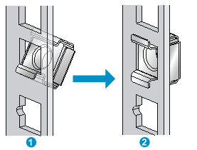
3. Install six cage nuts in the square holes in each rack post, as shown in Figure 4.
Figure 4 Installing a cage nut
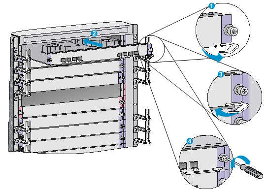
4. Align the installation holes on the front end of a slide rail with the cage nuts on a front rack post, and use six screws to attach the slide rail to the front rack post. Figure 5 uses the right slide rail as an example.
Figure 5 Attaching the right slide rail to the front right rack post
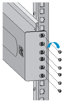
5. Keep the slide rail horizontal and adjust its length until the installation holes on the rear end of the slide rail touch the cage nuts on the rear rack post. Then use screws to attach the slide rail to the rear rack post.
6. Repeat steps 4 and 5 to install the other slide rail. Make sure the two slide rails are at the same height so that the switch can be placed on them horizontally.
Installing cage nuts
1. Determine and mark the cage nut installation holes in either of the following methods:
? Mark the cage nut installation holes as shown in Figure 6.
? Use other tools such as a tape. Align the tape with a mounting bracket. Mark the tape according to the cage nut installation holes on the mounting bracket. Align the tape with the rack posts and mark the installation holes on the rack posts.
Figure 6 Cage nut installation holes
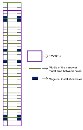
Figure 7 Marking the cage nut installation holes
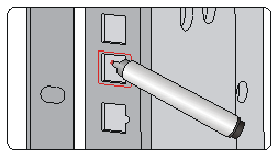
2. Install the cage nuts in the marked square holes on the rack posts.
Installing the switch in the rack
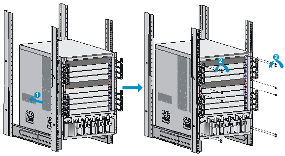
Follow these guidelines when you install the switch in the rack:
· To avoid equipment damage or bodily injury, use a minimum of two people to lift the switch. H3C recommends that you use a mechanical lift to move the switch.
· Do not hold the filler panels, filler panel handles, or the air vents of chassis to carry the chassis. Any attempt to carry the switch with these parts might cause equipment damage or even bodily injury.
· After placing the switch on the slide rails, do not leave go of your hands immediately because this might tip the switch. Tipping the switch can cause switch damage and even bodily injury.
Figure 8 Installing the switch in the rack
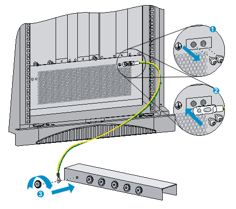
Grounding the switch
|
|
CAUTION: · Use the provided grounding cable (yellow-green grounding cable). · Connect the grounding cable to the grounding system in the equipment room. Do not connect it to a fire main or lightning rod. |
Figure 9 Grounding the switch
Installing FRUs
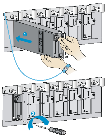
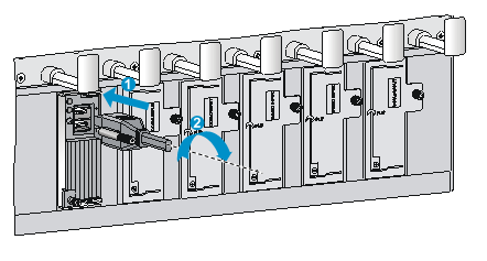
Installing a card
|
|
CAUTION: Before installing a card in the chassis, make sure the connectors on the card are not broken or blocked. |
Figure 10 Installing a card
Installing a power module
|
|
CAUTION: · Provide a circuit breaker for each power module and verify that the circuit breaker is off before installation. · Do not install power modules of different models on the same switch. · To avoid power module damage, move the power module by supporting its bottom instead of holding its handle. |
After you push the power module into the slot, press the power module handle inward until it is secured in place, and then fasten the captive screws on the power module.
Figure 11 Installing a power module
Connecting power cords
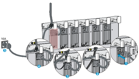
Connecting an AC power cord
|
|
CAUTION: Before you connect an AC power cord, make sure the circuit breaker for the power cord is switched off. |
Figure 12 Connecting an AC power cord
Connecting a DC power cord
|
|
CAUTION: · Provide a circuit breaker for each DC power cord. · Before connecting the DC power cord, make sure the circuit breakers for both the positive (+) and negative (-) lines are switched off. |
Figure 13 Connecting a DC power cord
Accessing the switch for the first time
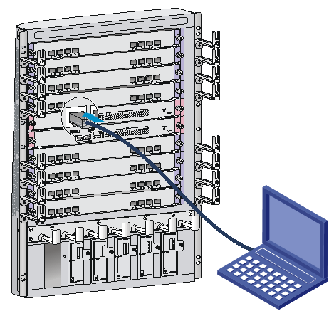
Connecting the console cable
The first time you access the switch you must use a console cable to connect a console terminal, for example, a PC, to the console port on the switch.
To connect the console cable to the console port:
1. Connect the DB-9 connector of the console cable to the 9-core serial port on the terminal.
2. Connect the crimped RJ-45 connector of the console cable to the console port on the switch.
Figure 14 Connecting the console port to a PC
Setting terminal parameters
To configure and manage the switch, you must run terminal emulator program, HyperTerminal or PuTTY on the configuration terminal. You can use the terminal emulator program to connect a network device, a Telnet, or an SSH site. For more information about the terminal emulator programs, see the user guides for these programs.
The following are the required terminal settings:
· Bits per second—9600.
· Data bits—8.
· Stop bits—1.
· Parity—None.
· Flow control—None.
Powering on the switch
1. Make sure the power cords are connected correctly to the power source, and the power source is supplying power correctly.
2. Turn on the circuit breakers for the power modules.
3. Power on the switch.
4. Verify that the LEDs on the switch are in the states as described Table 4. For more information about the LEDs, see H3C S7508E-X Switch Installation Guide.
Table 4 LED status when the switching is operating correctly
|
Card |
LED |
Status |
|
MPU |
LINK |
Steady on |
|
ACT |
Flashing or off |
|
|
OK |
Steady on |
|
|
FAIL |
Off |
|
|
RUN |
Flashing |
|
|
ALM |
Flashing or off |
|
|
Switching fabric module |
RUN |
Flashing or steady on |
|
ALM |
Off |
|
|
Power module |
Power input |
Steady green |
|
Power output |
Steady green |
|
|
Fan tray |
OK |
Steady on |
|
FAIL |
Off |
Obtaining documentation
Take the following steps to get related documents from the H3C website at www.h3c.com.hk.
1. Go to http://www.h3c.com.hk/Technical_Documents.
2. Choose the desired product category and model.
