- Table of Contents
- Related Documents
-
| Title | Size | Download |
|---|---|---|
| 01-IRF configuration | 959.31 KB |
Multi-active handling procedure
General restrictions and configuration guidelines
IRF physical interface requirements
Feature compatibility and configuration restrictions
Setup and configuration task list
Preconfiguring IRF member devices in standalone mode
Assigning a member ID to each IRF member device
Specifying a priority for each member device
Binding physical interfaces to IRF ports
Saving configuration to the next-startup configuration file
Connecting IRF physical interfaces·
Setting the operating mode to IRF mode
Bulk-configuring basic IRF settings for a device in IRF mode
Configuring IRF member devices in IRF mode
Changing the member ID of a device
Changing the priority of a member device
Adding physical interfaces to an IRF port
Configuring a member device description
Configuring IRF link load sharing mode
Configuring the IRF bridge MAC address
Enabling software auto-update for software image synchronization
Setting the IRF link down report delay
Isolating an unused IRF member ID
Displaying and maintaining an IRF fabric
LACP MAD-enabled IRF configuration example for a two-chassis IRF fabric
BFD MAD-enabled IRF configuration example for a two-chassis IRF fabric
ARP MAD-enabled IRF configuration example for a two-chassis IRF fabric
ND MAD-enabled IRF configuration example for a two-chassis IRF fabric
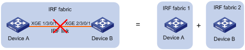
Configuration example for restoring standalone mode
Four-chassis IRF fabric configuration example
Configuration restrictions and guidelines
Parent fabric size restrictions
PEX physical interface requirements
PEX cabling for one tier of PEXs
IRF 3 system setup and configuration task list
Planning the IRF 3 system setup
Enabling IRF 3 capability on the parent device
Configuring IRF 3 settings on the parent fabric for PEXs
Assigning virtual chassis numbers to one tier of PEXs
Assigning virtual chassis numbers to a PEX stack
Creating a PEX port group and assigning the PEX ports of a PEX stack to the group
Assigning physical interfaces to PEX ports
Configuring PEX link load sharing mode
Connecting the PEXs to the parent fabric·
Removing PEXs from an IRF 3 system
Displaying and maintaining PEXs
IRF 3 system configuration examples
IRF 3 system with one tier of PEXs configuration example
IRF 3 system with a PEX stack configuration example
Setting up an IRF fabric
Overview
The Intelligent Resilient Framework (IRF) technology virtualizes multiple physical devices at the same layer into one virtual fabric to provide data center class availability and scalability. IRF virtualization technology offers processing power, interaction, unified management, and uninterrupted maintenance of multiple devices.
Figure 1 shows an IRF fabric that has two member devices, which appear as a single node to the upper-layer and lower-layer devices.
Figure 1 IRF application scenario
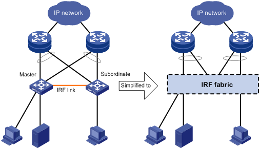
IRF provides the following benefits:
· Simplified topology and easy management—An IRF fabric appears as one node and is accessible at a single IP address on the network. You can use this IP address to log in at any member device to manage all the members of the IRF fabric. In addition, you do not need to run the spanning tree feature among the IRF members.
· 1:N redundancy—In an IRF fabric, one member acts as the master to manage and control the entire IRF fabric. All the other members process services while backing up the master. When the master fails, all the other member devices elect a new master from among them to take over without interrupting services.
· IRF link aggregation—You can assign several physical links between neighboring members to their IRF ports to create a load-balanced aggregate IRF connection with redundancy.
· Multichassis link aggregation—You can use the Ethernet link aggregation feature to aggregate the physical links between the IRF fabric and its upstream or downstream devices across the IRF members.
· Network scalability and resiliency—Processing capacity of an IRF fabric equals the total processing capacities of all the members. You can increase ports, network bandwidth, and processing capacity of an IRF fabric simply by adding member devices without changing the network topology.
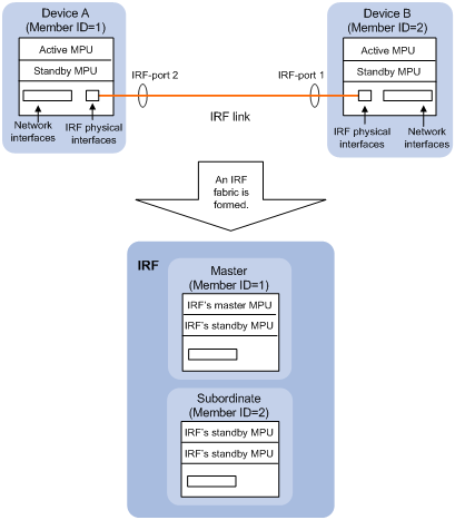
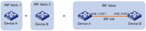
As shown in Figure 2, Device A and Device B form a two-chassis IRF fabric. The fabric has four MPUs (one active and three standbys), and two times the number of interface modules that a single device provides. The IRF fabric manages the physical and software resources of Device A and Device B in a centralized manner.
Figure 2 Two-chassis IRF fabric implementation schematic diagram
Network topology
The device supports daisy-chain or ring topology for IRF fabrics. IRF does not support the full mesh topology. For information about connecting IRF member devices, see "Connecting IRF physical interfaces."
Basic concepts
Operating mode
The device operates in one of the following modes:
· Standalone mode—The device cannot form an IRF fabric with other devices.
· IRF mode—The device can form an IRF fabric with other devices.
IRF member roles
IRF uses two member roles: master and standby (called subordinate throughout the documentation).
When devices form an IRF fabric, they elect a master to manage and control the IRF fabric, and all the other devices back up the master. When the master device fails, the other devices elect a new master automatically. For more information about master election, see "Master election."
IRF member ID
An IRF fabric uses member IDs to uniquely identify and manage its members. This member ID information is included as the first part of interface numbers and file paths to uniquely identify interfaces and files in an IRF fabric. Two devices cannot form an IRF fabric if they use the same member ID. A device cannot join an IRF fabric if its member ID has been used in the fabric.
For example, after you assign a device with a member ID of 2 to an IRF fabric, the name of interface GigabitEthernet 3/0/1 changes to GigabitEthernet 2/3/0/1. The file path changes from slot1#flash:/test.cfg to chassis2#slot1#flash:/test.cfg.
By default, the standby MPU of a device is automatically assigned the same ID as the active MPU.
MPU roles
Each IRF member device has one or two MPUs. The following are MPU roles:
|
Role |
Description |
|
Master MPU |
Active MPU of the master device. It is also called the global active MPU. You configure and manage the entire IRF fabric at the CLI of the global active MPU. |
|
Active MPU |
Active MPU on each member device. An active MPU performs the following operations: · Manages the local device, including synchronizing configuration with the local standby MPU, processing protocol packets, and creating and maintaining route entries. · Processes IRF-related events, such as master election and topology collection. |
|
Standby MPU |
For the master MPU, all other MPUs are standby MPUs, including active MPUs on subordinate devices. If a member device has two MPUs, the MPU backing up the local active MPU is the local standby MPU from the perspective of the member device. |
IRF port
An IRF port is a logical interface that connects IRF member devices. Every IRF-capable device has two IRF ports.
In standalone mode, the IRF ports are named IRF-port 1 and IRF-port 2.
In IRF mode, the IRF ports are named IRF-port n/1 and IRF-port n/2, where n is the member ID of the device. The two IRF ports are referred to as IRF-port 1 and IRF-port 2 in this book.
To use an IRF port, you must bind a minimum of one physical interface to it. The physical interfaces assigned to an IRF port automatically form an aggregate IRF link. An IRF port goes down when all its IRF physical interfaces are down.
IRF physical interface
IRF physical interfaces connect IRF member devices and must be bound to an IRF port. They forward traffic between member devices, including IRF protocol packets and data packets that must travel across IRF member devices.
For more information about physical interfaces that can be used for IRF links, see "IRF physical interface requirements."
MAD
An IRF link failure causes an IRF fabric to split in two IRF fabrics operating with the same Layer 3 configurations, including the same IP address. To avoid IP address collision and network problems, IRF uses multi-active detection (MAD) mechanisms to detect the presence of multiple identical IRF fabrics, handle collisions, and recover from faults.
IRF domain ID
One IRF fabric forms one IRF domain. IRF uses IRF domain IDs to uniquely identify IRF fabrics and prevent IRF fabrics from interfering with one another.
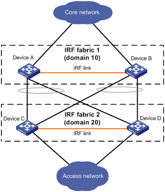
As shown in Figure 3, IRF fabric 1 contains Device A and Device B, and IRF fabric 2 contains Device C and Device D. Both fabrics use the LACP aggregate links between them for MAD. When a member device receives an extended LACPDU for MAD, it checks the domain ID to see whether the packet is from the local IRF fabric. Then, the device can handle the packet correctly.
Figure 3 A network that contains two IRF domains
IRF split
IRF split occurs when an IRF fabric breaks up into multiple IRF fabrics because of IRF link failures, as shown in Figure 4. The split IRF fabrics operate with the same IP address. IRF split causes routing and forwarding problems on the network. To quickly detect a multi-active collision, configure a minimum of one MAD mechanism (see "Configuring MAD").
IRF merge
IRF merge occurs when two split IRF fabrics reunite or when two independent IRF fabrics are united, as shown in Figure 5.
Member priority
Member priority determines the possibility of a member device to be elected the master. A member with higher priority is more likely to be elected the master.
Configuration synchronization
IRF uses a strict running-configuration synchronization mechanism. In an IRF fabric, all devices obtain and run the running configuration of the master. Any configuration changes are automatically propagated from the master to the remaining devices. The configuration files of these devices are retained, but the files do not take effect. The devices use their own startup configuration files only after they are removed from the IRF fabric.
For more information about configuration management, see Fundamentals Configuration Guide.
Loop elimination mechanism
Loop control protocols such as the spanning tree feature cannot be configured on IRF physical interfaces. However, IRF has its own mechanism to eliminate loops. Before an IRF member device forwards a packet, it identifies whether loops exist on the forwarding path based on the source and destination physical interfaces and the IRF topology. If a loop exists, the device discards the packet on the source interface of the looped path. This loop elimination mechanism will drop a large number of broadcast packets on the IRF physical interfaces. When you use SNMP tools, do not monitor packet forwarding on the IRF physical interfaces to reduce SNMP notifications of packet drops.
Master election
Master election occurs each time the IRF fabric topology changes in the following situations:
· The IRF fabric is established.
· The master device fails or is removed.
· The IRF fabric splits.
· Independent IRF fabrics merge.
|
|
NOTE: Master election does not occur when two split IRF fabrics merge. All member devices in the Recovery-state IRF fabric reboot to join the active IRF fabric as subordinate members. The master device of the active IRF fabric is the master device of the merged IRF fabric. |
Master election selects a master in descending order:
1. Current master, even if a new member has higher priority.
When an IRF fabric is being formed, all members consider themselves as the master. This rule is skipped.
2. Member with higher priority.
3. Member with the longest system uptime.
Two members are considered to start up at the same time if the difference between their startup times is equal to or less than 10 minutes. For these members, the next tiebreaker applies.
4. Member with the lowest CPU MAC address.
For the setup of a new IRF fabric, the subordinate devices must reboot to complete the setup after the master election.
For an IRF merge, devices must reboot if they are in the IRF fabric that fails the master election. The reboot can be performed automatically or manually.
Multi-active handling procedure
The multi-active handling procedure includes detection, collision handling, and failure recovery.
Detection
MAD identifies each IRF fabric with a domain ID and an active ID (the member ID of the master). If multiple active IDs are detected in a domain, MAD determines that an IRF collision or split has occurred.
For more information about the MAD mechanisms and their application scenarios, see "MAD mechanisms."
Collision handling
When MAD detects a multi-active collision, it sets all IRF fabrics except one to the Recovery state. The fabric that is not placed in Recovery state can continue to forward traffic. The Recovery-state IRF fabrics are inactive and cannot forward traffic.
LACP MAD and BFD MAD use the following process to handle a multi-active collision:
1. Compare the number of members in each fabric.
2. Set all fabrics to the Recovery state except the one that has the most members.
3. Compare the member IDs of their masters if all IRF fabrics have the same number of members.
4. Set all fabrics to the Recovery state except the one that has the lowest numbered master.
5. Shut down all network ports and interfaces in the Recovery-state fabrics except for the following ports and interfaces:
¡ IRF physical interfaces.
¡ Ports and interfaces you have specified with the mad exclude interface command.
In contrast, ARP MAD and ND MAD do not compare the number of members in fabrics. These MAD mechanisms use the following process to handle a multi-active collision:
1. Compare the member IDs of the masters in the IRF fabrics.
2. Set all fabrics to the Recovery state except the one that has the lowest numbered master.
3. Take the same action on the network ports and interfaces in Recovery-state fabrics as LACP MAD and BFD MAD.
Failure recovery
To merge two split IRF fabrics, first repair the failed IRF link and remove the IRF link failure.
· If the IRF fabric in Recovery state fails before the failure is recovered, repair the failed IRF fabric and the failed IRF link.
· If the active IRF fabric fails before the failure is recovered, enable the inactive IRF fabric to take over the active IRF fabric. Then, recover the MAD failure.
MAD mechanisms
IRF provides MAD mechanisms by extending LACP, BFD, ARP, and IPv6 ND. You can configure a minimum of one MAD mechanism on an IRF fabric for prompt IRF split detection.
· Do not configure LACP MAD together with ARP MAD or ND MAD, because they handle collisions differently.
· Do not configure BFD MAD together with ARP MAD or ND MAD. BFD MAD is exclusive with the spanning tree feature, but ARP MAD and ND MAD require the spanning tree feature. At the same time, BFD MAD handles collisions differently than ARP MAD and ND MAD.
Table 1 compares the MAD mechanisms and their application scenarios.
Table 1 Comparison of MAD mechanisms
|
MAD mechanism |
Advantages |
Disadvantages |
Application scenario |
|
· Detection speed is fast. · Does not require MAD-dedicated physical links or Layer 3 interfaces. |
Requires an intermediate device that supports extended LACP for MAD. |
Link aggregation is used between the IRF fabric and its upstream or downstream device. For information about LACP, see Layer 2—LAN Switching Configuration Guide. |
|
|
· Detection speed is fast. · No intermediate device is required for two-chassis IRF fabrics. · Intermediate device, if used, can come from any vendor. |
· Requires MAD dedicated physical links and Layer 3 interfaces, which cannot be used for transmitting user traffic. · If no intermediate device is used, any two IRF members must have a BFD MAD link to each other. · If an intermediate device is used, every IRF member must have a BFD MAD link to the intermediate device. |
· No special requirements for network scenarios. · If no intermediate device is used, this mechanism is only suitable for two-chassis IRF fabrics that have members that are geographically close to one another. For information about BFD, see High Availability Configuration Guide. |
|
|
· No intermediate device is required. · Intermediate device, if used, can come from any vendor. · Does not require MAD dedicated ports. |
· Detection speed is slower than BFD MAD and LACP MAD. · The spanning tree feature must be enabled. |
Spanning tree-enabled non-link aggregation IPv4 network scenario. For information about ARP, see Layer 3—IP Services Configuration Guide. |
|
|
· No intermediate device is required. · Intermediate device, if used, can come from any vendor. · Does not require MAD dedicated ports. |
· Detection speed is slower than BFD MAD and LACP MAD. · The spanning tree feature must be enabled. |
Spanning tree-enabled non-link aggregation IPv6 network scenario. |
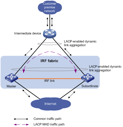
LACP MAD
As shown in Figure 6, LACP MAD has the following requirements:
· Every IRF member must have a link with an intermediate device.
· All the links form a dynamic link aggregation group.
· The intermediate device must be a device that supports extended LACP for MAD.
The IRF member devices send extended LACPDUs that convey a domain ID and an active ID. The intermediate device transparently forwards the extended LACPDUs received from one member device to all the other member devices.
· If the domain IDs and active IDs sent by all the member devices are the same, the IRF fabric is integrated.
· If the extended LACPDUs convey the same domain ID but different active IDs, a split has occurred. LACP MAD handles this situation as described in "Collision handling."
BFD MAD
|
|
IMPORTANT: BFD MAD is supported only on the default MDC. |
On a two-chassis IRF fabric, BFD MAD can work with or without an intermediate device. On a three- or four-chassis IRF fabric, BFD MAD must work with an intermediate device.
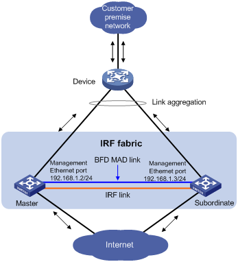
BFD MAD can be used on common Ethernet ports or management Ethernet ports. If management Ethernet ports are used, you must select the management Ethernet port on the active MPU of each member device for BFD MAD links.
Figure 7 shows a typical BFD MAD application scenario on common Ethernet ports. Figure 8 shows a typical BFD MAD application scenario on management Ethernet ports.
To use BFD MAD:
· Set up dedicated BFD MAD link between each pair of IRF members or between each IRF member and the intermediate device. Do not use the BFD MAD links for any other purposes.
· If common Ethernet ports are used for BFD MAD links, you must configure BFD MAD on a VLAN interface. Perform the following tasks:
¡ Assign the ports connected by BFD MAD links to the same VLAN. The VLAN must be unique across MDCs and the network.
¡ Create a VLAN interface for the VLAN, and assign a MAD IP address to each member on the VLAN interface.
On the intermediate device (if any), you must create the VLAN and assign the ports on the BFD MAD links to the VLAN.
· If management Ethernet ports are used for BFD MAD, assign a MAD IP address to each member device on the management Ethernet port of the global active MPU. On the intermediate device (if any), assign the ports on the BFD links to the same VLAN.
|
|
NOTE: · The MAD addresses identify the member devices and must belong to the same subnet. · Of all management Ethernet ports on an IRF fabric, only the management Ethernet port on the global active MPU is accessible. |
Figure 7 BFD MAD scenario for common Ethernet ports

Figure 8 BFD MAD scenario for management Ethernet ports
With BFD MAD, the master attempts to establish BFD sessions with other member devices by using its MAD IP address as the source IP address.
· If the IRF fabric is integrated, only the MAD IP address of the master takes effect. The master cannot establish a BFD session with any other member. If you execute the display bfd session command, the state of the BFD sessions is Down.
· When the IRF fabric splits, the IP addresses of the masters in the split IRF fabrics take effect. The masters can establish a BFD session. If you execute the display bfd session command, the state of the BFD session between the two devices is Up.
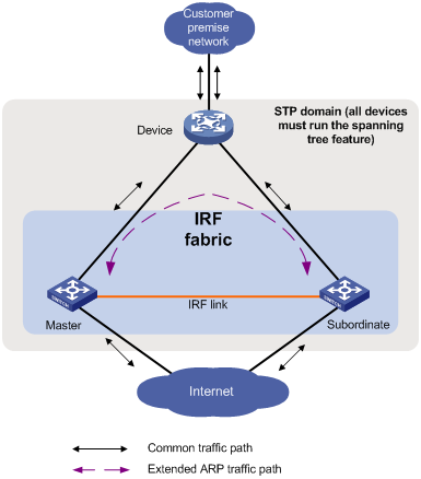
ARP MAD
ARP MAD detects multi-active collisions by using extended ARP packets that convey the IRF domain ID and the active ID.
You can set up ARP MAD links between neighbor IRF member devices, or between each IRF member device and an intermediate device (see Figure 9). If an intermediate device is used, you must also run the spanning tree feature between the IRF fabric and the intermediate device.
Each IRF member compares the domain ID and the active ID in incoming extended ARP packets with its domain ID and active ID.
· If the domain IDs are different, the extended ARP packet is from a different IRF fabric. The device does not continue to process the packet with the MAD mechanism.
· If the domain IDs are the same, the device compares the active IDs:
¡ If the active IDs are different, the IRF fabric has split.
¡ If the active IDs are the same, the IRF fabric is integrated.
ND MAD
ND MAD detects multi-active collisions by using NS packets to transmit the IRF domain ID and the active ID.
You can set up ND MAD links between neighbor IRF member devices or between each IRF member device and an intermediate device (see Figure 10). If an intermediate device is used, you must also run the spanning tree protocol between the IRF fabric and the intermediate device.

Each IRF member device compares the domain ID and the active ID in incoming NS packets with its domain ID and active ID:
· If the domain IDs are different, the NS packet is from a different IRF fabric. The device does not continue to process the packet with the MAD mechanism.
· If the domain IDs are the same, the device compares the active IDs:
¡ If the active IDs are different, the IRF fabric has split.
¡ If the active IDs are the same, the IRF fabric is integrated.
General restrictions and configuration guidelines
For a successful IRF setup, follow the restrictions and guidelines in this section and the setup procedure in "Setup and configuration task list."
IRF fabric size
An S7500E IRF fabric can contain a maximum of two chassis in the following situations:
· The number of IRF physical interfaces exceeds eight for an IRF port.
· The extended binding mode is used on IRF physical interfaces.
· The 10-GE or 40-GE ports on the LSQM2MPUD0 or LSQM1SRP8X2QE0 MPU are used as IRF physical interfaces.
· The ports on any of the following modules are used as IRF physical interfaces:
¡ SA modules.
¡ SC modules:
- LSQM2GP24TSSC0.
- LSQM2GP44TSSC0.
- LSQM2GT24PTSSC0.
- LSQM2GT24TSSC0.
In other situations, an S7500E IRF fabric can contain a maximum of four chassis.
Hardware compatibility
All S7500E switches are IRF capable except for the S7502E switch. An H3C S7500E switch can form an IRF fabric only with devices in the same series.
Software requirements
All IRF member devices must run the same software image version. Make sure the software auto-update feature is enabled on all member devices.
MPU requirements
To operate correctly, an IRF fabric must meet the following MPU requirements:
· Every IRF member has a minimum of one MPU.
· Every IRF member must use the same model of MPUs.
IRF physical interface requirements
Use the following physical interfaces for IRF links:
· 10-GE fiber ports.
· 40-GE fiber ports.
Selecting transceiver modules and cables
When you select transceiver modules and cables, follow these restrictions and guidelines:
· Use XFP, SFP+, QSFP+, or CFP transceiver modules and fibers for a long-distance connection.
· Use SFP+, QSFP+, or QSFP+ to SFP+ DAC cables for a short-distance connection.
· Make sure the transceiver modules at the two ends of an IRF link are the same type. For more information about transceiver modules, see the device installation guide.
Restrictions on grouped 10-GE ports on interface modules
The 10-GE ports on the LSQM1TGS12EC0 interface module are grouped by port number in order, starting from 1. Each group contains four ports.
The ports on the LSQM2TGS16SF0 interface module are divided into the following groups:
· Ports 1, 2, 15, and 16.
· Ports 3 through 5.
· Ports 6 through 8.
· Ports 9 through 11.
· Ports 12 through 14.
If you use the ports in a group for IRF links, follow these restrictions and guidelines:
· You must use all or none of the ports for IRF links. The ports can be bound to different IRF ports.
· Before you bind one 10-GE port to an IRF port or remove it from the IRF port, you must shut down all the ports in the group. If any of the ports are in up state, the bind or remove action will fail.
· Bring up the ports after you complete the operations.
Restrictions on 40-GE QSFP+ ports on interface modules
Port split (the using tengige command) and combination (the using fortygige command) require a card reboot. As a best practice to avoid topology change, complete these operations before you add the device to an IRF fabric. When you perform these operations in an IRF fabric, make sure you understand the impact on the IRF fabric topology. For more information about 40-GE port split and combination operations, see Interface Configuration Guide.
If you use the 40-GE QSFP+ ports on interface modules for IRF links, follow these restrictions and guidelines:
· You can use a 40-GE QSFP+ port for IRF links, or use the breakout interfaces of the QSFP+ port for IRF links.
· If you use the 10-GE breakout interfaces of a 40-GE port for IRF links, follow these restrictions and guidelines:
¡ You must use all or none of the four 10-GE breakout interfaces for IRF links. The four breakout interfaces can be bound to different IRF ports.
¡ Before you bind one 10-GE breakout interface to an IRF port or remove it from the IRF port, you must shut down all the 10-GE breakout interfaces. If any of the breakout interfaces are in up state, the bind or remove action will fail.
¡ Bring up the breakout interfaces after you complete the operations.
Restrictions on 10-GE and 40-GE ports on MPUs
If you use 10-GE or 40-GE ports on the LSQM2MPUD0 or LSQM1SRP8X2QE0 MPU for IRF links, follow these restrictions and guidelines:
· Ports on interface modules cannot be used for IRF links.
· Ports bound to all IRF ports in an IRF fabric must be located on the same type of MPU.
· Ports at the ends of an IRF link must operate at the same rate.
· IRF 3 is not supported on the device.
Connecting IRF ports
When you connect two neighboring IRF members, follow these restrictions and guidelines:
· You must connect the physical interfaces of IRF-port 1 on one member to the physical interfaces of IRF-port 2 on the other.
· Do not connect physical interfaces of both IRF ports on one member device to the physical interfaces of both IRF ports on the other device.
· Make sure the two ends of an aggregate IRF link have the same number of IRF physical interfaces.
Feature compatibility and configuration restrictions
ECMP
To form an IRF fabric, all member devices in the IRF fabric must support the same maximum number of ECMP routes. For more information about ECMP, see Layer 3—IP Routing Configuration Guide.
IRF mode
To form an IRF fabric, all member devices must use the same IRF mode setting, normal, light, or enhanced.
To add a new MPU or replace an MPU, make sure the added MPU or replacement MPU is operating in the same IRF mode as the IRF fabric.
To use the IRF fabric as the parent fabric in an IRF 3 system, all member devices must operate in enhanced or light IRF mode. IRF 3 system size varies by IRF mode. For more information about IRF modes, see "Setting up an IRF 3 system."
MDC
When you configure MDC on an IRF fabric, follow these restrictions and guidelines:
· If the IRF fabric splits, do not change the MDC settings on any IRF member devices before they reunite.
· Before you use the undo mdc command to delete an MDC, remove IRF port bindings for the physical interfaces on the MDC and save the configuration. To identify physical interfaces bound to IRF ports, use the display irf link command.
· Except for the commands in Table 2, all IRF commands are available only on the default MDC.
Table 2 IRF commands available on both default and non-default MDCs
|
Command category |
Commands |
|
Display commands |
display irf link |
|
MAD commands |
mad arp enable mad enable mad nd enable mad exclude interface |
For more information about MDCs, see "Configuring MDCs."
System operating mode
All member devices in the IRF fabric must work in the same system operating mode (set by using the system-working-mode command). For more information about the system operating mode, see Fundamentals Configuration Guide.
Licensing requirements
For a license-based feature to run correctly on an IRF fabric, make sure the licenses installed for the feature on all member devices are the same. For more information about feature licensing, see Fundamentals Configuration Guide.
Configuration backup
As a best practice, back up the next-startup configuration file on a device before adding the device to an IRF fabric as a subordinate.
A subordinate device's next-startup configuration file might be overwritten if the master and the subordinate use the same file name for their next-startup configuration files. You can use the backup file to restore the original configuration after removing the subordinate from the IRF fabric.
Setup and configuration task list
To set up an IRF fabric, perform the following tasks:
Planning the IRF fabric setup
Consider the following items when you plan an IRF fabric:
· Hardware compatibility and restrictions.
· IRF fabric size.
· Master switch.
· IRF physical interfaces.
· Member ID and priority assignment scheme.
· Fabric topology and cabling scheme.
For more information about hardware and cabling, see the switch installation guide.
Preconfiguring IRF member devices in standalone mode
Perform the preconfiguration tasks on every IRF member device. These settings take effect on each member device after their operating mode changes to IRF.
Assigning a member ID to each IRF member device
Assign a unique IRF member ID to a device before changing the device's operating mode to IRF.
The member ID is saved in both active and standby MPUs. The standby MPU might store a different member ID than the active MPU after an MPU replacement. For consistency, the system updates the member ID in the active MPU automatically to the standby MPU when the difference is detected.
To assign a member ID to the device in standalone mode:
|
Step |
Command |
Remarks |
|
1. Enter system view. |
system-view |
N/A |
|
2. Assign an IRF member ID to the device. |
irf member member-id |
By default, the IRF member ID is 1. |
Specifying a priority for each member device
IRF member priority represents the possibility for a device to be elected the master in an IRF fabric. The higher the priority, the higher the possibility.
To specify a priority for the device in standalone mode:
|
Step |
Command |
Remarks |
|
1. Enter system view. |
system-view |
N/A |
|
2. Specify a priority for the device. |
irf priority priority |
The default IRF member priority is 1. |
Binding physical interfaces to IRF ports
To establish an IRF connection between two devices, you must bind a minimum of one physical interface to IRF-port 1 on one device and to IRF-port 2 on the other.
You must configure IRF physical interfaces as Layer 2 interfaces. Layer 3 interfaces cannot be bound to IRF ports. To configure a physical interface as a Layer 2 interface, use the port link-mode bridge command. For more information about this command, see Interface Configuration Guide.
In standalone mode, IRF port binding operations do not affect the current configuration of the interface. However, when the operating mode changes to IRF mode, the default configuration is restored on the physical interface. You can only execute the following commands on the physical interface:
· Basic Ethernet interface commands:
¡ description
¡ flow-interval
¡ shutdown
For more information about these commands, see Interface Command Reference.
· The itu-channel command. For more information about the command, see Fundamentals Command Reference.
· LLDP commands:
¡ lldp admin-status
¡ lldp check-change-interval
¡ lldp enable
¡ lldp encapsulation snap
¡ lldp notification remote-change enable
¡ lldp tlv-enable
For more information about these commands, see Layer 2—LAN Switching Command Reference.
To bind physical interfaces to IRF ports:
|
Step |
Command |
Remarks |
|
1. Enter system view. |
system-view |
N/A |
|
2. Enter IRF port view. |
irf-port irf-port-number |
N/A |
|
3. Bind a physical interface to the IRF port. |
port group interface interface-type interface-number [ mode { enhanced | extended } ] |
By default, no physical interfaces are bound to an IRF port. Repeat this step to assign multiple physical interfaces to the IRF port. You can bind physical interfaces on different modules to the same IRF port. Each IRF port can have a maximum of 16 physical interfaces. Make sure the two ends of an IRF link use the same binding mode. Make sure all physical interfaces bound to an IRF port use the same binding mode. In standalone mode, you can configure the IRF physical interfaces of an IRF port to use different binding modes. However, only one binding mode takes effect after the operating mode changes from standalone to IRF. The binding mode of the first IRF physical interface in the configuration file has the highest priority. If the extended mode is used, an IRF fabric can contain a maximum of two chassis. |
Saving configuration to the next-startup configuration file
Save the running configuration before converting to the IRF mode. The mode change requires a reboot, which causes all unsaved settings to be lost.
Perform the following task in any view:
|
Task |
Command |
|
Save the running configuration to the next-startup configuration file. |
save [ safely ] [ backup | main ] [ force ] |
Connecting IRF physical interfaces
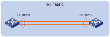
When you connect two neighboring IRF members, connect the physical interfaces of IRF-port 1 on one member to the physical interfaces of IRF-port 2 on the other (see Figure 11).
For example, you have four chassis: A, B, C, and D. IRF-port 1 and IRF-port 2 are represented by A1 and A2 on chassis A, represented by B1 and B2 on chassis B, and so on. To connect the four chassis into a ring topology of A-B-C-D(A), the IRF link cabling scheme must be one of the following:
· A1-B2, B1-C2, C1-D2, and D1-A2.
· A2-B1, B2-C1, C2-D1, and D2-A1.
Figure 11 Connecting IRF physical interfaces
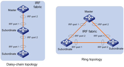
Connect the devices into a daisy-chain topology or a ring topology. A ring topology is more reliable (see Figure 12). In ring topology, the failure of one IRF link does not cause the IRF fabric to split as in daisy-chain topology. Rather, the IRF fabric changes to a daisy-chain topology without interrupting network services.
To use the ring topology, you must have a minimum of three member devices.
|
|
IMPORTANT: Optical transmission devices can be deployed to relay the IRF links. No other devices are allowed between neighboring IRF member devices. |
Figure 12 Daisy-chain topology vs. ring topology
Setting the operating mode to IRF mode
By default, the device operates in standalone mode. To assign the device to an IRF fabric, you must change its operating mode to IRF mode.
To set the operating mode of a device to IRF mode:
|
Step |
Command |
Remarks |
|
1. (Optional.) Verify that a unique IRF member ID has been assigned to the device. |
display irf configuration |
Check the MemberID field. |
|
2. Enter system view. |
system-view |
N/A |
|
3. Set the operating mode to IRF mode. |
chassis convert mode irf |
The default operating mode is standalone mode. |
After you change the operating mode, the device automatically reboots for the change to take effect.
During the reboot, you may choose to have the system automatically convert the startup configuration file. Automatic configuration conversion prevents slot- or interface-related settings from becoming invalid. For example, the system adds member ID information to interface numbers and file paths in IRF mode.
To restore the standalone mode, use the undo chassis convert mode command.
|
|
TIP: IRF generates packets on a device in IRF mode even if the device does not form an IRF fabric with any other devices. To conserve system resources, set a device to standalone mode after removing it from an IRF fabric. |
Accessing the IRF fabric
The IRF fabric appears as one device after it is formed. You configure and manage all IRF members at the CLI of the master. All settings you have made are automatically propagated to the IRF members.
The following methods are available for accessing an IRF fabric:
· Local login—Log in through the console port of any member device.
· Remote login—Log in at a Layer 3 interface on any member device by using methods including Telnet and SNMP.
When you log in to an IRF fabric, you are placed at the CLI of the master, regardless of at which member device you are logged in.
For more information, see login configuration in Fundamentals Configuration Guide.
Bulk-configuring basic IRF settings for a device in IRF mode
|
|
IMPORTANT: The device reboots immediately after you specify a new member ID for it. Make sure you are aware of the impact on the network. |
Use the easy IRF feature to bulk-configure basic IRF settings for a device in IRF mode, including the member ID, domain ID, priority, and IRF port bindings. To configure these settings separately in IRF mode, see "Configuring IRF member devices in IRF mode."
The easy IRF feature provides the following configuration methods:
· Interactive method—Enter the easy-irf command without parameters. The system will guide you to set the parameters step by step.
· Non-interactive method—Enter the easy-irf command with parameters.
As a best practice, use the interactive method if you are new to IRF.
When you specify IRF physical interfaces for an IRF port, you must follow the IRF port binding restrictions in "IRF physical interface requirements."
If you specify IRF physical interfaces by using the interactive method, you must also follow these restrictions and guidelines:
· Do not enter spaces between the interface type and interface number.
· Use a comma (,) to separate two physical interfaces. No spaces are allowed between interfaces.
To bulk-configure basic IRF settings for a device in IRF mode:
|
Step |
Command |
Remarks |
|
1. Enter system view. |
system-view |
N/A |
|
2. Bulk-configure basic IRF settings for the device. |
easy-irf [ member member-id [ renumber new-member-id ] domain domain-id [ priority priority ] [ irf-port1 interface-list1 ] [ irf-port2 interface-list2 ] ] |
Make sure the new member ID is unique in the IRF fabric to which the device will be added. If you execute this command multiple times, the following settings take effect: · The most recent settings for the member ID, domain ID, and priority. · IRF port bindings added through executions of the command. You can bind a maximum of 16 physical interfaces to an IRF port. To remove an IRF physical interface from an IRF port, you must use the undo port group interface command in IRF port view. |
Configuring IRF member devices in IRF mode
After you access the master's CLI, you can perform the tasks in this section or configure features in all other configuration guides for the device.
Changing the member ID of a device
|
|
CAUTION: In IRF mode, an IRF member ID change can invalidate member ID-related settings and cause data loss. Make sure you fully understand its impact on your live network. |
The new member ID takes effect at reboot. After the device reboots, the settings on all member ID-related physical resources (including common physical network ports) are removed, regardless of whether you have saved the configuration.
For a successful IRF merge, you must place a device in standalone mode before renumbering it in one of the following situations:
· The IRF physical interfaces of the device are 10-GE breakout interfaces of a 40-GE QSFP+ port.
· You are exchanging the member IDs of two devices. In this case, place both devices in standalone mode.
To change the member ID of a member device:
|
Step |
Command |
Remarks |
|
1. Enter system view. |
system-view |
N/A |
|
2. Change the member ID of a member device. |
irf member member-id renumber new-member-id |
By default, the device uses the member ID that is set in standalone mode. |
|
3. Save the running configuration. |
save [ safely ] [ force ] |
N/A |
|
4. Reboot the member device. |
reboot chassis chassis-number |
The chassis-number must be the same as the member-id specified in the irf member member-id renumber new-member-id command. |
Changing the priority of a member device
You can change the priority of a member device so it can be elected the master in the next master election.
A change to member priority can affect the master re-election result. However, it does not cause an immediate master re-election.
To change the priority of a member device:
|
Step |
Command |
Remarks |
|
1. Enter system view. |
system-view |
N/A |
|
2. Specify a priority for a member of an IRF fabric. |
irf member member-id priority priority |
The default IRF member priority is 1. |
Adding physical interfaces to an IRF port
An IRF port can have a maximum of 16 physical interfaces.
In IRF mode, you can add physical interfaces to an IRF port without traffic interruption on the IRF port.
Before you perform this task, disable IRF auto-merge.
When you perform this task, follow the IRF port binding restrictions and configuration guidelines in these sections:
· IRF physical interface requirements.
· Binding physical interfaces to IRF ports.
To configure IRF ports:
|
Step |
Command |
Remarks |
|
1. Enter system view. |
system-view |
N/A |
|
2. Enter Ethernet interface view or interface range view. |
· Enter interface range view: ¡ Method 1: ¡ Method 2: · Enter interface view: |
To shut down a range of IRF physical interfaces, enter interface range view. To shut down one IRF physical interface, enter its interface view. |
|
3. Shut down the physical interfaces. |
shutdown |
If you cannot shut down a physical interface, follow the system instruction to shut down its peer interface. |
|
4. Return to system view. |
quit |
N/A |
|
5. Enter IRF port view. |
irf-port member-id/port-number |
N/A |
|
6. Bind each physical interface to the IRF port. |
port group [ mdc mdc-name ] interface interface-type interface-number [ mode { enhanced | extended } ] |
By default, no physical interfaces are bound to an IRF port. Repeat this step to assign multiple physical interfaces to the IRF port. You can bind a maximum of 16 physical interfaces to an IRF port. Make sure the two ends of an IRF link use the same binding mode. Make sure all IRF physical interfaces of an IRF port use the same binding mode. In IRF mode, IRF physical interfaces of an IRF port cannot be configured to use different binding modes. If the extended mode is used, an IRF fabric can contain a maximum of two chassis. |
|
7. Return to system view. |
quit |
N/A |
|
8. Enter Ethernet interface view or interface range view. |
· Enter interface range view: ¡ Method 1: ¡ Method 2: · Enter interface view: |
N/A |
|
9. Bring up the physical interfaces. |
undo shutdown |
N/A |
|
10. Return to system view. |
quit |
N/A |
|
11. Save the running configuration. |
save |
Activating IRF port settings causes IRF merge and reboot. To avoid data loss, save the running configuration to the startup configuration file before you perform the operation. |
|
12. Activate the configuration on the IRF port. |
irf-port-configuration active |
After this step is performed, the state of the IRF port changes to UP. The member devices elect a master, and the subordinate device reboots automatically. After the IRF fabric is formed, you can add physical interfaces to an IRF port (in UP state) without repeating this step. |
Enabling IRF auto-merge
When two IRF fabrics merge, you must reboot the member devices in the IRF fabric that fails in the master election. The auto-merge feature enables the IRF fabric to automatically reboot all its member devices to complete the merge.
If this feature is disabled or does not take effect, you must manually reboot the devices that failed the master election to complete the merge.
To enable IRF auto-merge:
|
Step |
Command |
Remarks |
|
1. Enter system view. |
system-view |
N/A |
|
2. Enable IRF auto-merge. |
irf auto-merge enable |
By default, this feature is enabled. |
Configuring a member device description
|
Step |
Command |
Remarks |
|
1. Enter system view. |
system-view |
N/A |
|
2. Configure a description for a member device. |
irf member member-id description text |
By default, no member device description is configured. |
Configuring IRF link load sharing mode
On an IRF port, traffic is balanced across its physical links.
You can configure the IRF port to distribute traffic based on any combination of the following criteria:
· IP addresses.
· MAC addresses.
· Ingress ports.
The system displays an error message if a criteria combination is not supported.
Configure the IRF link load sharing mode for IRF links in system view or IRF port view:
· In system view, the configuration is global and takes effect on all IRF ports.
· In IRF port view, the configuration is port specific and takes effect only on the specified IRF port.
An IRF port preferentially uses the port-specific load sharing mode. If no port-specific load sharing mode is available, the IRF port uses the global load sharing mode.
Configuring the global load sharing mode
|
Step |
Command |
Remarks |
|
1. Enter system view. |
system-view |
N/A |
|
2. Configure the global IRF link load sharing mode. |
irf-port global load-sharing mode { destination-ip | destination-mac | ingress-port | source-ip | source-mac } * |
By default, the IRF link load sharing mode varies by service module. For information about the default link load sharing modes of different service modules, see device management in Fundamentals Configuration Guide. If you execute this command multiple times, the most recent configuration takes effect. |
Configuring a port-specific load sharing mode
Before you configure a port-specific load sharing mode, make sure you have bound a minimum of one physical interface to the IRF port.
To configure a port-specific load sharing mode for an IRF port:
|
Step |
Command |
Remarks |
|
1. Enter system view. |
system-view |
N/A |
|
2. Enter IRF port view. |
irf-port member-id/irf-port-number |
N/A |
|
3. Configure the port-specific load sharing mode. |
irf-port load-sharing mode { destination-ip | destination-mac | ingress-port | source-ip | source-mac } * |
By default, the IRF link load sharing mode varies by service module. For information about the default link load sharing modes of different service modules, see device management in Fundamentals Configuration Guide. If you execute this command multiple times, the most recent configuration takes effect. |
Configuring the IRF bridge MAC address
|
|
CAUTION: The bridge MAC address change causes transient traffic disruption. |
Use this feature to configure the bridge MAC address of an IRF fabric. Layer 2 protocols, such as LACP, use the IRF bridge MAC address to identify an IRF fabric. On a switched LAN, the bridge MAC address must be unique.
When IRF fabrics merge, IRF ignores the IRF bridge MAC address and only checks the bridge MAC address of each member device in the IRF fabrics. IRF merge fails if any two member devices have the same bridge MAC address.
After IRF fabrics merge, the merged IRF fabric uses the bridge MAC address of the merging IRF fabric that won the master election as the IRF bridge MAC address.
The following methods are available to configure the IRF bridge MAC address for an IRF fabric:
· Specifying a MAC address as the IRF bridge MAC address.
The IRF fabric always uses the specified MAC address as the IRF bridge MAC address.
· Configuring IRF bridge MAC persistence.
This feature specifies the amount of time an IRF fabric can continue using a MAC address as the IRF bridge MAC address after the address owner leaves. By default, the bridge MAC address of the master device becomes the IRF bridge MAC address upon the setup of the IRF fabric.
Configuration restrictions and guidelines
When you configure the IRF bridge MAC address, follow these restrictions and guidelines:
· The IRF bridge MAC persistence feature does not take effect if you specify the IRF bridge MAC address by using the irf mac-address mac-address command.
· If ARP MAD or ND MAD is used with the spanning tree feature, you must configure IRF bridge MAC persistence by using the undo irf mac-address persistent command. Do not specify a MAC address as the IRF bridge MAC address.
· If the IRF fabric has cross-member aggregate links, do not use the undo irf mac-address persistent command to avoid unnecessary traffic disruption.
Specifying a MAC address as the IRF bridge MAC address
You can specify the bridge MAC address of an existing IRF fabric for a new IRF fabric to replace the existing IRF fabric with transient packet loss.
To specify a MAC address as the IRF bridge MAC address:
|
Step |
Command |
Remarks |
|
1. Enter system view. |
system-view |
N/A |
|
2. Specify a MAC address as the IRF bridge MAC address. |
irf mac-address mac-address |
By default, an IRF fabric uses the bridge MAC address of the master as the IRF bridge MAC address. If an IRF fabric splits after you configure the IRF bridge MAC address, both the split IRF fabrics use the configured bridge MAC address as the IRF bridge MAC address. |
Configuring IRF bridge MAC persistence
Depending on the network condition, enable the IRF fabric to retain or change its bridge MAC address after the address owner leaves. Available options include:
· irf mac-address persistent timer—Bridge MAC address of the IRF fabric is retained for 6 minutes after the address owner leaves. If the owner does not return before the timer expires, the IRF fabric uses the bridge MAC address of the current master as its bridge MAC address. This option avoids unnecessary bridge MAC address changes caused by device reboot, transient link failure, or purposeful link disconnection.
· irf mac-address persistent always—Bridge MAC address of the IRF fabric does not change after the address owner leaves.
· undo irf mac-address persistent—Bridge MAC address of the current master replaces the original one as soon as the owner of the original bridge MAC address leaves.
To configure the IRF bridge MAC persistence setting:
|
Step |
Command |
Remarks |
|
1. Enter system view. |
system-view |
N/A |
|
2. Configure IRF bridge MAC persistence. |
· Retain the
bridge MAC address permanently even if the address owner has
left the fabric: · Retain the
bridge MAC address for 6 minutes after the address
owner leaves the fabric: · Change the bridge MAC address as soon
as the address owner leaves the fabric: |
By default, the IRF bridge MAC address does not change after the address owner has left the fabric. |
Enabling software auto-update for software image synchronization
|
|
IMPORTANT: To ensure a successful software auto-update in a multi-user environment, prevent anyone from rebooting or swapping member devices or MPUs during the auto-update process. To inform administrators of the auto-update status, configure the information center to output the status message to configuration terminals (see Network Management and Monitoring Configuration Guide). |
The software auto-update feature automatically propagates the software images of the global active MPU to all other MPUs in the IRF fabric.
To join an IRF fabric, an MPU must use the same software images as the global active MPU in the fabric.
When you add an MPU to the IRF fabric, software auto-update compares the startup software images of the MPU with the current software images of the IRF global active MPU. If the two sets of images are different, the MPU automatically performs the following operations:
1. Downloads the current software images of the global active MPU.
2. Sets the downloaded images as the main startup software images.
3. Reboots with the new software images to rejoin the IRF fabric.
You must manually update the new MPU with the software images running on the IRF fabric in the following situations:
· Software auto-update is disabled.
· Software auto-update fails to update software. This situation might occur if the IRF fabric cannot identify the software version used on the new MPU.
|
|
NOTE: To synchronize software from the active MPU to the standby MPU in standalone mode, use the undo version check ignore and version auto-update enable commands. For more information about these commands, see software upgrade in Fundamentals Configuration Guide. |
Configuration prerequisites
Make sure the MPU you are adding to the IRF fabric has sufficient storage space for the new software images.
If sufficient storage space is not available, the MPU automatically deletes the current software images. If the reclaimed space is still insufficient, the MPU cannot complete the auto-update. You must reboot the device that holds the MPU, and then access the BootWare menus to delete files.
Configuration procedure
To enable software image synchronization:
|
Step |
Command |
Remarks |
|
1. Enter system view. |
system-view |
N/A |
|
2. Enable software auto-update. |
irf auto-update enable |
By default, software auto-update is enabled. |
Setting the IRF link down report delay
To prevent frequent IRF splits and merges during link flapping, configure the IRF ports to delay reporting link down events.
An IRF port does not report a link down event to the IRF fabric immediately after its link changes from up to down. If the IRF link state is still down when the delay is reached, the port reports the change to the IRF fabric.
IRF ports do not delay link up events. They report the link up event immediately after the IRF link comes up.
When you configure the IRF link down report delay, follow these restrictions and guidelines:
· Make sure the IRF link down report delay is shorter than the maximum CCM lifetime and BFD session lifetime. For more information about CFD and BFD, see High Availability Configuration Guide.
· As a best practice, set the delay to 0 seconds in the following situations:
¡ The IRF fabric requires a fast master/subordinate or IRF link switchover.
¡ The BFD, BFD MAD, GR, or RRPP feature is used.
To set the IRF link down report delay:
|
Step |
Command |
Remarks |
|
1. Enter system view. |
system-view |
N/A |
|
2. Set the IRF link down report delay. |
irf link-delay interval |
The default IRF link down report delay is 1 second. The greater the interval, the slower the service recovery. |
Isolating an unused IRF member ID
This feature prevents an IRF fabric from creating CRC errors or traffic storms.
CRC errors or traffic storms occur if an IRF member device tags inter-chassis packets with a valid unused member ID. This issue is typically caused by poor-quality fiber modules, fibers, or cables on IRF links.
To avoid CRC errors or traffic storms, isolate the unused member IDs in the valid member ID range. When an unused member ID is isolated, the member devices will drop all packets that are tagged with the member ID.
|
|
IMPORTANT: Before you assign an isolated ID to a new member device, remove the isolation setting for the member ID. |
To isolate an unused IRF member ID:
|
Step |
Command |
Remarks |
|
1. Enter system view. |
system-view |
N/A |
|
2. Isolate an unused IRF member ID. |
irf isolate member member-id |
By default, no member IDs are isolated. This command is supported only in IRF mode. This command takes effect only when the ports on interface modules are used as IRF physical interfaces. |
Configuring MAD
When you configure MAD, follow these restrictions and guidelines:
· You can configure a minimum of one MAD mechanism on an IRF fabric for prompt IRF split detection.
¡ Do not configure LACP MAD together with ARP MAD or ND MAD, because they handle collisions differently.
¡ Do not configure BFD MAD together with ARP MAD or ND MAD. BFD MAD is exclusive with the spanning tree feature, but ARP MAD and ND MAD require the spanning tree feature. At the same time, BFD MAD handles collisions differently than ARP MAD and ND MAD.
· If LACP MAD, ARP MAD, or ND MAD runs between two IRF fabrics, assign each fabric a unique IRF domain ID. (For BFD MAD, this task is optional.)
· BFD MAD is supported only on the default MDC.
· An IRF fabric has only one IRF domain ID.
¡ You can change the IRF domain ID by using the following commands: irf domain, mad enable, mad arp enable, or mad nd enable. The IRF domain IDs configured by using these commands overwrite each other.
¡ In an MDC environment, if you change the IRF domain ID in one MDC, the IRF domain IDs in all other MDCs change automatically. The irf domain command is available only on the default MDC. The mad enable, mad arp enable, and mad nd enable commands are available on any MDCs.
· To prevent a port or interface from being shut down when the IRF fabric transits to the Recovery state, use the mad exclude interface command. To bring up ports and interfaces in a Recovery-state IRF fabric, use the mad restore command instead of the undo shutdown command. The mad restore command activates the Recovery-state IRF fabric.
Configuring LACP MAD
When you use LACP MAD, follow these guidelines:
· The intermediate device must be a device that supports extended LACP for MAD.
· If the intermediate device is also an IRF fabric, assign the two IRF fabrics different domain IDs for correct split detection.
· Use dynamic link aggregation mode. MAD is LACP dependent. Even though LACP MAD can be configured on both static and dynamic aggregate interfaces, it takes effect only on dynamic aggregate interfaces.
· Configure link aggregation settings on the intermediate device.
To configure LACP MAD:
|
Step |
Command |
Remarks |
|
1. Enter system view. |
system-view |
N/A |
|
2. Assign a domain ID to the IRF fabric. |
irf domain domain-id |
The default IRF domain ID is 0. |
|
3. Create an aggregate interface and enter aggregate interface view. |
· Enter Layer 2 aggregate interface view: · Enter Layer 3 aggregate interface view: |
Perform this step also on the intermediate device. |
|
4. Configure the aggregation group to operate in dynamic aggregation mode. |
link-aggregation mode dynamic |
By default, an aggregation group operates in static aggregation mode. Perform this step also on the intermediate device. |
|
5. Enable LACP MAD. |
mad enable |
By default, LACP MAD is disabled. |
|
6. Return to system view. |
quit |
N/A |
|
7. Enter Ethernet interface view or interface range view. |
· Enter interface range view: ¡ Method 1: ¡ Method 2: · Enter Ethernet interface view: |
To assign a range of ports to the aggregation group, enter interface range view. To assign one port to the aggregation group, enter Ethernet interface view. |
|
8. Assign the Ethernet port or the range of Ethernet ports to the specified aggregation group. |
port link-aggregation group group-id |
Multichassis link aggregation is allowed. Also perform this step on the intermediate device. |
Configuring BFD MAD that uses common Ethernet ports
Configure BFD MAD on a VLAN interface if you use common Ethernet ports for BFD MAD.
When you configure BFD MAD settings, follow these restrictions and guidelines:
|
Category |
Restrictions and guidelines |
|
BFD MAD VLAN |
· Do not enable BFD MAD on VLAN-interface 1. · If you are using an intermediate device, perform the following tasks on both the IRF fabric and the intermediate device: ¡ Create a VLAN and VLAN interface for BFD MAD. ¡ Assign the ports of BFD MAD links to the BFD MAD VLAN. · Make sure the BFD MAD VLAN belongs to only one MDC. The VLAN ID is unique across MDCs. · Make sure the IRF fabrics on the network use different BFD MAD VLANs. · Make sure the BFD MAD VLAN contains only ports on the BFD MAD links. Exclude a port from the BFD MAD VLAN if the port is not on the BFD MAD link. For example, if you have assigned the port to all VLANs by using the port trunk permit vlan all command, use the undo port trunk permit command to exclude the port from the BFD MAD VLAN. |
|
BFD MAD VLAN and feature compatibility |
Do not use the BFD MAD VLAN for any purpose other than configuring BFD MAD. · Configure only the mad bfd enable and mad ip address commands on the BFD MAD-enabled VLAN interface. If you configure other features, both BFD MAD and other features on the interface might run incorrectly. · Disable the spanning tree feature on any Layer 2 Ethernet ports in the BFD MAD VLAN. The MAD feature is mutually exclusive with the spanning tree feature. · Do not bind a BFD MAD-enabled VLAN interface to a VPN instance. The MAD feature is mutually exclusive with VPN. |
|
MAD IP address |
· To avoid problems, only use the mad ip address command to configure IP addresses on the BFD MAD-enabled VLAN interface. Do not configure an IP address by using the ip address command or configure a VRRP virtual address on the BFD MAD-enabled VLAN interface. · Make sure all the MAD IP addresses are on the same subnet. · MAD IP addresses must be unique among all IP addresses on the IRF fabric. |
|
BFD MAD and IRF link down report delay restrictions |
Set the IRF link down report delay to 0 seconds to avoid unnecessary recalculations. |
To configure BFD MAD that uses common Ethernet ports:
|
Step |
Command |
Remarks |
|
1. Enter system view. |
system-view |
N/A |
|
2. (Optional.) Assign a domain ID to the IRF fabric. |
irf domain domain-id |
By default, the domain ID of an IRF fabric is 0. |
|
3. Create a VLAN dedicated to BFD MAD. |
vlan vlan-id |
The default VLAN on the device is VLAN 1. |
|
4. Return to system view. |
quit |
N/A |
|
5. Enter interface view or interface range view. |
· Enter interface range view: ¡ Method 1: ¡ Method 2: · Enter interface view: |
To assign a range of ports to the BFD MAD VLAN, enter interface range view. To assign one port to the BFD MAD VLAN, enter Ethernet interface view. |
|
6. Assign the port or the range of ports to the BFD MAD VLAN. |
· Assign the port to the VLAN as an access port:
· Assign the port to the VLAN as a trunk port: · Assign the port to the VLAN as a hybrid
port: |
The link type of BFD MAD ports can be access, trunk, or hybrid. The default link type of a port is access. |
|
7. Return to system view. |
quit |
N/A |
|
8. Enter VLAN interface view. |
interface vlan-interface vlan-interface-id |
N/A |
|
9. Enable BFD MAD. |
mad bfd enable |
By default, BFD MAD is disabled. |
|
10. Assign a MAD IP address to a member device on the VLAN interface. |
mad ip address ip-address { mask | mask-length } member member-id |
By default, no MAD IP address is configured for a member device on a VLAN interface. Repeat this step to assign a MAD IP address to each member device on the VLAN interface. |
Configuring BFD MAD that uses management Ethernet ports
When you configure BFD MAD that uses management Ethernet ports, follow these restrictions and guidelines:
|
Category |
Restrictions and guidelines |
|
Management Ethernet ports for BFD MAD |
· If you are using an intermediate device, connect the management Ethernet ports on each member device to the common Ethernet ports on the intermediate device. To avoid BFD MAD failure caused by an active/standby MPU switchover, connect the management Ethernet port on each MPU to the intermediate device. |
|
BFD MAD VLAN |
· On the intermediate device (if any), create a VLAN for BFD MAD, and assign the ports used for BFD MAD to the VLAN. On the IRF fabric, you do not need to assign the management Ethernet ports to a VLAN. · As a best practice, do not configure other features on the VLAN used for BFD MAD. · Make sure the IRF fabrics on the network use different BFD MAD VLANs. · Make sure the BFD MAD VLAN on the intermediate device contains only ports on the BFD MAD links. |
|
BFD MAD-enabled management Ethernet port and feature compatibility |
Do not bind a BFD MAD-enabled management Ethernet port to a VPN instance. The MAD feature is mutually exclusive with VPN. |
|
MAD IP address |
· Use the mad ip address command instead of the ip address command to configure MAD IP addresses on the BFD MAD-enabled management Ethernet ports. · Make sure all the MAD IP addresses are on the same subnet. · MAD IP addresses must be unique among all IP addresses on the IRF fabric. |
|
BFD MAD and IRF link down report delay restrictions |
Set the IRF link down report delay to 0 seconds to avoid unnecessary recalculations. |
To configure BFD MAD that uses management Ethernet ports:
|
Step |
Command |
Remarks |
|
1. Enter system view. |
system-view |
N/A |
|
2. (Optional.) Assign a domain ID to the IRF fabric. |
irf domain domain-id |
By default, the domain ID of an IRF fabric is 0. |
|
3. Enter management Ethernet interface view. |
interface M-GigabitEthernet interface-number |
Enter the view of the management Ethernet port on the global active MPU to perform the subsequent steps. |
|
4. Enable BFD MAD. |
mad bfd enable |
By default, BFD MAD is disabled. |
|
5. Assign a MAD IP address to each member device. |
mad ip address ip-address { mask | mask-length } member member-id |
By default, no MAD IP address is assigned to any member device. |
Configuring ARP MAD
When you use ARP MAD, follow these guidelines:
· Do not configure ARP MAD on VLAN-interface 1.
· Do not use the VLAN configured for ARP MAD for any other purposes.
· If an intermediate device is used, you can use common data links as ARP MAD links. If no intermediate device is used, set up dedicated ARP MAD links between IRF member devices.
· If an intermediate device is used, make sure the following requirements are met:
¡ Run the spanning tree feature between the IRF fabric and the intermediate device. Make sure there is only one ARP MAD link in forwarding state. For more information about the spanning tree feature and its configuration, see Layer 2—LAN Switching Configuration Guide.
¡ Enable the IRF fabric to change its bridge MAC address as soon as the bridge MAC owner leaves.
¡ Create an ARP MAD VLAN and assign the ports on the ARP MAD links to the VLAN.
¡ If the intermediate device is also an IRF fabric, assign the two IRF fabrics different domain IDs for correct split detection.
To configure ARP MAD:
|
Step |
Command |
Remarks |
|
1. Enter system view. |
system-view |
N/A |
|
2. Assign a domain ID to the IRF fabric. |
irf domain domain-id |
The default IRF domain ID is 0. |
|
3. Configure the IRF bridge MAC address to change as soon as the address owner leaves. |
undo irf mac-address persistent |
By default, the IRF fabric's bridge MAC address does not change after the address owner leaves. |
|
4. Create a VLAN dedicated to ARP MAD. |
vlan vlan-id |
The default VLAN on the device is VLAN 1. |
|
5. Return to system view. |
quit |
N/A |
|
6. Enter Ethernet interface view or interface range view. |
· Enter interface range view: ¡ Method 1: ¡ Method 2: · Enter interface view: |
To assign a range of ports to the ARP MAD VLAN, enter interface range view. To assign one port to the ARP MAD VLAN, enter Ethernet interface view. |
|
7. Assign the port or the range of ports to the ARP MAD VLAN. |
· Assign the port to the VLAN as an access port:
· Assign the port to the VLAN as a trunk port: · Assign the port to the VLAN as a hybrid
port: |
The link type of ARP MAD ports can be access, trunk, or hybrid. The default link type of a port is access. |
|
8. Return to system view. |
quit |
N/A |
|
9. Enter VLAN interface view. |
interface vlan-interface vlan-interface-id |
N/A |
|
10. Assign the interface an IP address. |
ip address ip-address { mask | mask-length } |
By default, no IP addresses are assigned to a VLAN interface. |
|
11. Enable ARP MAD. |
mad arp enable |
By default, ARP MAD is disabled. |
Configuring ND MAD
When you use ND MAD, follow these guidelines:
· Do not configure ND MAD on VLAN-interface 1.
· Do not use the VLAN configured for ND MAD for any other purposes.
· If an intermediate device is used, you can use common data links as ND MAD links. If no intermediate device is used, set up dedicated ND MAD links between IRF member devices.
· If an intermediate device is used, make sure the following requirements are met:
¡ Run the spanning tree feature between the IRF fabric and the intermediate device. Make sure there is only one ND MAD link in forwarding state. For more information about the spanning tree feature and its configuration, see Layer 2—LAN Switching Configuration Guide.
¡ Enable the IRF fabric to change its bridge MAC address as soon as the bridge MAC owner leaves.
¡ Create an ND MAD VLAN and assign the ports on the ND MAD links to the VLAN.
¡ If the intermediate device is also an IRF fabric, assign the two IRF fabrics different domain IDs for correct split detection.
To configure ND MAD:
|
Step |
Command |
Remarks |
|
1. Enter system view. |
system-view |
N/A |
|
2. Assign a domain ID to the IRF fabric. |
irf domain domain-id |
The default IRF domain ID is 0. |
|
3. Configure the IRF bridge MAC address to change as soon as the address owner leaves. |
undo irf mac-address persistent |
By default, the IRF fabric's bridge MAC address does not change after the address owner leaves. |
|
4. Create a VLAN dedicated to ND MAD. |
vlan vlan-id |
The default VLAN on the device is VLAN 1. |
|
5. Return to system view. |
quit |
N/A |
|
6. Enter Ethernet interface view or interface range view. |
· Enter interface range view: ¡ Method 1: ¡ Method 2: · Enter interface view: |
To assign a range of ports to the ND MAD VLAN, enter interface range view. To assign one port to the ND MAD VLAN, enter Ethernet interface view. |
|
7. Assign the port or the range of ports to the ND MAD VLAN. |
· Assign the port to the VLAN as an access port:
· Assign the port to the VLAN as a trunk port: · Assign the port to the VLAN as a hybrid
port: |
The link type of ND MAD ports can be access, trunk, or hybrid. The default link type of a port is access. |
|
8. Return to system view. |
quit |
N/A |
|
9. Enter VLAN interface view. |
interface vlan-interface vlan-interface-id |
N/A |
|
10. Assign the interface an IPv6 address. |
ipv6 address { ipv6-address/pre-length | ipv6 address pre-length } |
By default, no IPv6 addresses are assigned to a VLAN interface. |
|
11. Enable ND MAD. |
mad nd enable |
By default, ND MAD is disabled. |
Excluding a network port or interface from the shutdown action upon detection of multi-active collision
By default, all ports and interfaces except the console port and IRF physical interfaces shut down automatically when the IRF fabric transits to the Recovery state.
You can exclude a network port or interface from the shutdown action for management or other special purposes. For example:
· Exclude a port from the shutdown action so you can Telnet to the port for managing the device.
· Exclude a VLAN interface and its Layer 2 ports from the shutdown action so you can log in through the VLAN interface.
Configuration restrictions and guidelines
When you configure this feature, follow these restrictions and guidelines:
· If the Layer 2 ports of a VLAN interface are distributed on multiple member devices, the exclusion operation might introduce IP collision risks. The VLAN interface might be up on both active and inactive IRF fabrics.
· Do not exclude the following ports and interfaces from the shutdown action:
¡ Aggregate interfaces used for MAD and their member ports.
¡ VLAN interfaces used for MAD and the Ethernet ports in the VLANs.
¡ Management Ethernet ports used for MAD.
Configuration procedure
To configure a network port or interface to not shut down when the IRF fabric transits to the Recovery state:
|
Step |
Command |
Remarks |
|
1. Enter system view. |
system-view |
N/A |
|
2. Configure a network port or interface to not shut down when the IRF fabric transits to the Recovery state. |
mad exclude interface interface-type interface-number |
By default, all network ports and interfaces on a Recovery-state IRF fabric are shut down, except for the IRF physical interfaces and console port. |
Recovering an IRF fabric
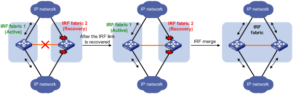
After the failed IRF link between two split IRF fabrics is recovered, log in to the inactive IRF fabric, and use the reboot command to reboot all its members. If the irf auto-merge enable command has been configured, the inactive IRF member devices automatically reboot after the failed link is recovered. After these member devices join the active IRF fabric as subordinates, IRF merge is complete, as shown in Figure 13.
Figure 13 Recovering the IRF fabric
If the active IRF fabric fails before the IRF link is recovered (see Figure 14), use the mad restore command on the inactive IRF fabric to recover the inactive IRF fabric. The command also brings up all network ports and interfaces that were shut down by MAD. After you repair the IRF link, the two parts merge into a unified IRF fabric.
Figure 14 Active IRF fabric fails before the IRF link is recovered
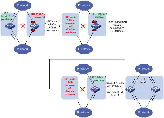
To manually recover an inactive IRF fabric:
|
Step |
Command |
|
1. Enter system view. |
system-view |
|
2. Recover the inactive IRF fabric. |
mad restore |
After the IRF fabric is recovered, all ports and interfaces that have been shut down by MAD come up automatically.
Displaying and maintaining an IRF fabric
Execute display commands in any view.
|
Task |
Command |
|
Display information about all IRF members. |
display irf |
|
Display the IRF fabric topology. |
display irf topology |
|
Display IRF link information. |
display irf link |
|
Display IRF configuration. |
display irf configuration |
|
Display load sharing mode for IRF links. |
display irf-port load-sharing mode [ irf-port [ member-id/irf-port-number ] ] |
|
Display MAD configuration. |
display mad [ verbose ] |
Configuration examples
This section provides IRF configuration examples for IRF fabrics that use different MAD mechanisms.
LACP MAD-enabled IRF configuration example for a two-chassis IRF fabric
Network requirements
As shown in Figure 15, set up a two-chassis IRF fabric at the access layer of the enterprise network.
Configure LACP MAD on the multichassis aggregation to Device C, an H3C device that supports extended LACP.
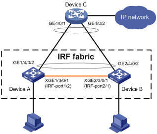
Configuration procedure
|
|
IMPORTANT: Between two neighboring IRF members, IRF links must be bound to IRF-port 1 on one member and to IRF-port 2 on the other. |
1. Configure Device A:
# Assign member ID 1 to Device A, and bind Ten-GigabitEthernet 3/0/1 to IRF-port 2.
<Sysname> system-view
[Sysname] irf member 1
[Sysname] irf-port 2
[Sysname-irf-port2] port group interface ten-gigabitethernet 3/0/1
[Sysname-irf-port2] quit
# Save the configuration.
[Sysname] quit
<Sysname> save
# Enable IRF mode.
<Sysname> system-view
[Sysname] chassis convert mode irf
The device will switch to IRF mode and reboot. You are recommended to save the current running configuration and specify the configuration file for the next startup. Continue? [Y/N]:y
Do you want to convert the content of the next startup configuration file flash:/startup.cfg to make it available in IRF mode? [Y/N]:y
Please wait...
Saving the converted configuration file to the main board succeeded.
Slot 1:
Saving the converted configuration file succeeded.
Now rebooting, please wait...
2. Configure Device B:
# Assign member ID 2 to Device B, and bind Ten-GigabitEthernet 3/0/1 to IRF-port 1.
<Sysname> system-view
[Sysname] irf member 2
[Sysname] irf-port 1
[Sysname-irf-port1] port group interface ten-gigabitethernet 3/0/1
[Sysname-irf-port1] quit
# Save the configuration.
[Sysname] quit
<Sysname> save
# Connect the two devices as shown in Figure 15.
# Enable IRF mode on Device B.
<Sysname> system-view
[Sysname] chassis convert mode irf
The device will switch to IRF mode and reboot. You are recommended to save the current running configuration and specify the configuration file for the next startup. Continue? [Y/N]:y
Do you want to convert the content of the next startup configuration file flash:/startup.cfg to make it available in IRF mode? [Y/N]:y
Please wait...
Saving the converted configuration file to the main board succeeded.
Slot 1:
Saving the converted configuration file succeeded.
Now rebooting, please wait...
Device B and Device A form an IRF fabric after Device B reboots.
3. Configure LACP MAD:
# Assign domain ID 1 to the IRF fabric.
<Sysname> system-view
[Sysname] irf domain 1
# Create a dynamic aggregate interface and enable LACP MAD.
[Sysname] interface bridge-aggregation 2
[Sysname-Bridge-Aggregation2] link-aggregation mode dynamic
[Sysname-Bridge-Aggregation2] mad enable
You need to assign a domain ID (range: 0-4294967295)
[Current domain is: 1]:
The assigned domain ID is: 1
MAD LACP only enable on dynamic aggregation interface.
[Sysname-Bridge-Aggregation2] quit
# Assign GigabitEthernet 1/4/0/2 and GigabitEthernet 2/4/0/2 to the aggregate interface.
[Sysname] interface gigabitethernet 1/4/0/2
[Sysname-GigabitEthernet1/4/0/2] port link-aggregation group 2
[Sysname-GigabitEthernet1/4/0/2] quit
[Sysname] interface gigabitethernet 2/4/0/2
[Sysname-GigabitEthernet2/4/0/2] port link-aggregation group 2
4. Configure Device C as the intermediate device:
|
|
CAUTION: If the intermediate device is also an IRF fabric, assign the two IRF fabrics different domain IDs for correct split detection. False detection causes IRF split. |
# Create a dynamic aggregate interface.
<Sysname> system-view
[Sysname] interface bridge-aggregation 2
[Sysname-Bridge-Aggregation2] link-aggregation mode dynamic
[Sysname-Bridge-Aggregation2] quit
# Assign GigabitEthernet 4/0/1 and GigabitEthernet 4/0/2 to the aggregate interface.
[Sysname] interface gigabitethernet 4/0/1
[Sysname-GigabitEthernet4/0/1] port link-aggregation group 2
[Sysname-GigabitEthernet4/0/1] quit
[Sysname] interface gigabitethernet 4/0/2
[Sysname-GigabitEthernet4/0/2] port link-aggregation group 2
BFD MAD-enabled IRF configuration example for a two-chassis IRF fabric
Network requirements
As shown in Figure 16, set up an IRF fabric at the distribution layer of the network.
· Configure BFD MAD in the IRF fabric and set up BFD MAD links between the member devices.
· Disable the spanning tree feature on the ports used for BFD MAD, because the two features conflict with each other.
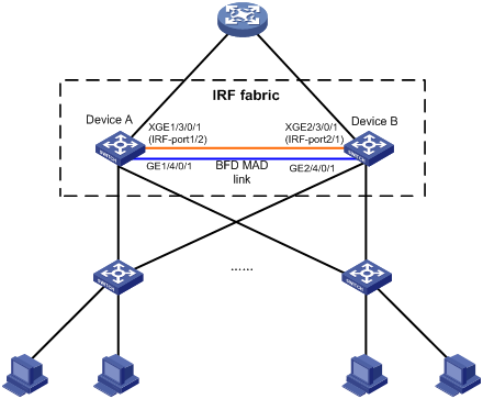
Configuration procedure
1. Configure Device A:
# Assign member ID 1 to Device A, and bind Ten-GigabitEthernet 3/0/1 to IRF-port 2.
<Sysname> system-view
[Sysname] irf member 1
[Sysname] irf-port 2
[Sysname-irf-port2] port group interface ten-gigabitethernet 3/0/1
[Sysname-irf-port2] quit
# Save the configuration.
[Sysname] quit
<Sysname> save
# Enable IRF mode.
<Sysname> system-view
[Sysname] chassis convert mode irf
The device will switch to IRF mode and reboot. You are recommended to save the current running configuration and specify the configuration file for the next startup. Continue? [Y/N]:y
Do you want to convert the content of the next startup configuration file flash:/startup.cfg to make it available in IRF mode? [Y/N]:y
Please wait...
Saving the converted configuration file to the main board succeeded.
Slot 1:
Saving the converted configuration file succeeded.
Now rebooting, please wait...
2. Configure Device B:
# Assign member ID 2 to Device B, and bind Ten-GigabitEthernet 3/0/1 to IRF-port 1.
<Sysname> system-view
[Sysname] irf member 2
[Sysname] irf-port 1
[Sysname-irf-port1] port group interface ten-gigabitethernet 3/0/1
[Sysname-irf-port1] quit
# Save the configuration.
[Sysname] quit
<Sysname> save
# Connect the two devices as shown in Figure 16.
# Enable IRF mode on Device B.
<Sysname> system-view
[Sysname] chassis convert mode irf
The device will switch to IRF mode and reboot. You are recommended to save the current running configuration and specify the configuration file for the next startup. Continue? [Y/N]:y
Do you want to convert the content of the next startup configuration file flash:/startup.cfg to make it available in IRF mode? [Y/N]:y
Please wait...
Saving the converted configuration file to the main board succeeded.
Slot 1:
Saving the converted configuration file succeeded.
Now rebooting, please wait...
Device B and Device A form an IRF after Device B reboots.
3. Configure BFD MAD:
# Set the IRF link down report delay to 0 seconds.
<Sysname> system-view
[Sysname] irf link-delay 0
# Create VLAN 3, and add GigabitEthernet 1/4/0/1 and GigabitEthernet 2/4/0/1 to VLAN 3.
[Sysname] vlan 3
[Sysname-vlan3] port gigabitethernet 1/4/0/1 gigabitethernet 2/4/0/1
[Sysname-vlan3] quit
# Create VLAN-interface 3, and configure a MAD IP address for each member device on the VLAN interface.
[Sysname] interface vlan-interface 3
[Sysname-Vlan-interface3] mad bfd enable
[Sysname-Vlan-interface3] mad ip address 192.168.2.1 24 member 1
[Sysname-Vlan-interface3] mad ip address 192.168.2.2 24 member 2
[Sysname-Vlan-interface3] quit
# Disable the spanning tree feature on GigabitEthernet 1/4/0/1 and GigabitEthernet 2/4/0/1.
[Sysname] interface gigabitethernet 1/4/0/1
[Sysname-gigabitethernet1/4/0/1] undo stp enable
[Sysname-gigabitethernet1/4/0/1] quit
[Sysname] interface gigabitethernet 2/4/0/1
[Sysname-gigabitethernet2/4/0/1] undo stp enable
ARP MAD-enabled IRF configuration example for a two-chassis IRF fabric
Network requirements
As shown in Figure 17, set up a two-chassis IRF fabric at the distribution layer of the enterprise network.
· Configure ARP MAD for the IRF fabric and use Device C as an intermediate device. Device C can come from any vendor.
· To prevent loops, enable the spanning tree feature between the IRF fabric and Device C.

Configuration procedure
1. Configure Device A:
# Assign member ID 1 to Device A, and bind Ten-GigabitEthernet 3/0/1 to IRF-port 2.
<Sysname> system-view
[Sysname] irf member 1
[Sysname] irf-port 2
[Sysname-irf-port2] port group interface ten-gigabitethernet 3/0/1
[Sysname-irf-port2] quit
# Save the configuration.
[Sysname] quit
<Sysname> save
# Enable IRF mode.
<Sysname> system-view
[Sysname] chassis convert mode irf
The device will switch to IRF mode and reboot. You are recommended to save the current running configuration and specify the configuration file for the next startup. Continue? [Y/N]:y
Do you want to convert the content of the next startup configuration file flash:/startup.cfg to make it available in IRF mode? [Y/N]:y
Please wait...
Saving the converted configuration file to the main board succeeded.
Slot 1:
Saving the converted configuration file succeeded.
Now rebooting, please wait...
2. Configure Device B:
# Assign member ID 2 to Device B, and bind Ten-GigabitEthernet 3/0/1 to IRF-port 1.
<Sysname> system-view
[Sysname] irf member 2
[Sysname] irf-port 1
[Sysname-irf-port1] port group interface ten-gigabitethernet 3/0/1
[Sysname-irf-port1] quit
# Save the configuration.
[Sysname] quit
<Sysname> save
# Connect the two devices as shown in Figure 17.
# Enable IRF mode on Device B.
<Sysname> system-view
[Sysname] chassis convert mode irf
The device will switch to IRF mode and reboot. You are recommended to save the current running configuration and specify the configuration file for the next startup. Continue? [Y/N]:y
Do you want to convert the content of the next startup configuration file flash:/startup.cfg to make it available in IRF mode? [Y/N]:y
Please wait...
Saving the converted configuration file to the main board succeeded.
Slot 1:
Saving the converted configuration file succeeded.
Now rebooting, please wait...
Device B and Device A form an IRF after Device B reboots.
3. Configure ARP MAD on the IRF fabric:
# Enable the spanning tree feature globally, and map the ARP MAD VLAN to MSTI 1 in the MST region.
<Sysname> system-view
[Sysname] stp global enable
[Sysname] stp region-configuration
[Sysname-mst-region] region-name arpmad
[Sysname-mst-region] instance 1 vlan 3
[Sysname-mst-region] active region-configuration
[Sysname-mst-region] quit
# Configure the bridge MAC address of the IRF fabric to change as soon as the bridge MAC owner leaves.
[Sysname] undo irf mac-address persistent
# Set the domain ID of the IRF fabric to 1.
[Sysname] irf domain 1
# Create VLAN 3, and add GigabitEthernet 1/4/0/2 and GigabitEthernet 2/4/0/2 to VLAN 3.
[Sysname] vlan 3
[Sysname-vlan3] port gigabitethernet 1/4/0/2 gigabitethernet 2/4/0/2
[Sysname-vlan3] quit
# Create VLAN-interface 3, assign it an IP address, and enable ARP MAD on the interface.
[Sysname] interface vlan-interface 3
[Sysname-Vlan-interface3] mad arp enable
You need to assign a domain ID (range: 0-4294967295)
[Current domain is: 1]:
The assigned domain ID is: 1
[Sysname-Vlan-interface3] ip address 192.168.2.1 24
4. Configure Device C as the intermediate device:
|
|
CAUTION: If the intermediate device is also an IRF fabric, assign the two IRF fabrics different domain IDs for correct split detection. False detection causes IRF split. |
# Enable the spanning tree feature globally, and map the ARP MAD VLAN to MSTI 1 in the MST region.
<DeviceC> system-view
[DeviceC] stp global enable
[DeviceC] stp region-configuration
[DeviceC-mst-region] region-name arpmad
[DeviceC-mst-region] instance 1 vlan 3
[DeviceC-mst-region] active region-configuration
[DeviceC-mst-region] quit
# Create VLAN 3, and add GigabitEthernet 4/0/1 and GigabitEthernet 4/0/2 to VLAN 3.
[DeviceC] vlan 3
[DeviceC-vlan3] port gigabitethernet 4/0/1 gigabitethernet 4/0/2
[DeviceC-vlan3] quit
ND MAD-enabled IRF configuration example for a two-chassis IRF fabric
Network requirements
As shown in Figure 18, set up a two-chassis IRF fabric at the distribution layer of the enterprise network.
· Configure ND MAD for the IRF fabric and use Device C as an intermediate device. Device C can come from any vendor.
· To prevent loops, enable the spanning tree feature between the IRF fabric and Device C.
Configuration procedure
1. Configure Device A:
# Assign member ID 1 to Device A, and bind Ten-GigabitEthernet 3/0/1 to IRF-port 2.
<Sysname> system-view
[Sysname] irf member 1
[Sysname] irf-port 2
[Sysname-irf-port2] port group interface ten-gigabitethernet 3/0/1
[Sysname-irf-port2] quit
# Save the configuration.
[Sysname] quit
<Sysname> save
# Enable IRF mode.
<Sysname> system-view
[Sysname] chassis convert mode irf
The device will switch to IRF mode and reboot. You are recommended to save the current running configuration and specify the configuration file for the next startup. Continue? [Y/N]:y
Do you want to convert the content of the next startup configuration file flash:/startup.cfg to make it available in IRF mode? [Y/N]:y
Please wait...
Saving the converted configuration file to the main board succeeded.
Slot 1:
Saving the converted configuration file succeeded.
Now rebooting, please wait...
2. Configure Device B:
# Assign member ID 2 to Device B, and bind Ten-GigabitEthernet 3/0/1 to IRF-port 1.
<Sysname> system-view
[Sysname] irf member 2
[Sysname] irf-port 1
[Sysname-irf-port1] port group interface ten-gigabitethernet 3/0/1
[Sysname-irf-port1] quit
# Save the configuration.
[Sysname] quit
<Sysname> save
# Connect the two devices as shown in Figure 18.
# Enable IRF mode on Device B.
<Sysname> system-view
[Sysname] chassis convert mode irf
The device will switch to IRF mode and reboot. You are recommended to save the current running configuration and specify the configuration file for the next startup. Continue? [Y/N]:y
Do you want to convert the content of the next startup configuration file flash:/startup.cfg to make it available in IRF mode? [Y/N]:y
Please wait...
Saving the converted configuration file to the main board succeeded.
Slot 1:
Saving the converted configuration file succeeded.
Now rebooting, please wait...
Device B and Device A form an IRF after Device B reboots.
3. Configure ND MAD on the IRF fabric:
# Enable the spanning tree feature globally, and map the ND MAD VLAN to MSTI 1 in the MST region.
<Sysname> system-view
[Sysname] stp global enable
[Sysname] stp region-configuration
[Sysname-mst-region] region-name ndmad
[Sysname-mst-region] instance 1 vlan 3
[Sysname-mst-region] active region-configuration
[Sysname-mst-region] quit
# Configure the bridge MAC address of the IRF fabric to change as soon as the bridge MAC owner leaves.
[Sysname] undo irf mac-address persistent
# Set the domain ID of the IRF fabric to 1.
[Sysname] irf domain 1
# Create VLAN 3, and add GigabitEthernet 1/4/0/2 and GigabitEthernet 2/4/0/2 to VLAN 3.
[Sysname] vlan 3
[Sysname-vlan3] port gigabitethernet 1/4/0/2 gigabitethernet 2/4/0/2
[Sysname-vlan3] quit
# Create VLAN-interface 3, assign it an IP address, and enable ND MAD on the interface.
[Sysname] interface vlan-interface 3
[Sysname-Vlan-interface3] ipv6 address 2001::1 64
[Sysname-Vlan-interface3] mad nd enable
You need to assign a domain ID (range: 0-4294967295)
[Current domain is: 1]:
The assigned domain ID is: 1
4. Configure Device C as the intermediate device:
|
|
CAUTION: If the intermediate device is also an IRF fabric, assign the two IRF fabrics different domain IDs for correct split detection. False detection causes IRF split. |
# Enable the spanning tree feature globally, and map the ND MAD VLAN to MSTI 1 in the MST region.
<DeviceC> system-view
[DeviceC] stp global enable
[DeviceC] stp region-configuration
[DeviceC-mst-region] region-name ndmad
[DeviceC-mst-region] instance 1 vlan 3
[DeviceC-mst-region] active region-configuration
[DeviceC-mst-region] quit
# Create VLAN 3, and add GigabitEthernet 4/0/1 and GigabitEthernet 4/0/2 to VLAN 3.
[DeviceC] vlan 3
[DeviceC-vlan3] port gigabitethernet 4/0/1 gigabitethernet 4/0/2
[DeviceC-vlan3] quit
Configuration example for restoring standalone mode
Network requirements
Break the IRF fabric in Figure 19, and change the operating mode of Device A and Device B from IRF to standalone.
Configuration procedure
1. Identify the master.
<IRF> display irf
MemberID Slot Role Priority CPU-Mac Description
*+1 0 Master 1 00e0-fc0f-8C01 DeviceA
1 1 Standby 1 00e0-fc0f-8c02 DeviceA
2 0 Standby 1 00e0-fc0f-15e1 DeviceB
2 1 Standby 1 00e0-fc0f-15e2 DeviceB
--------------------------------------------------
* indicates the device is the master.
+ indicates the device through which the user logs in.
The Bridge MAC of the IRF is: 0000-fc00-313e
Auto upgrade : no
Mac persistent : always
Domain ID : 0
Auto merge : yes
IRF mode : normal
The output shows that Device A is the master.
2. Examine the configuration for VLAN interfaces.
If a VLAN interface has member ports on different member devices, change the IP address for the interface on each device to be unique.
3. Shut down IRF physical interfaces to disconnect all IRF links. In this example, shut down Ten-GigabitEthernet 1/3/0/1.
<IRF> system-view
[IRF] interface ten-gigabitethernet 1/3/0/1
[IRF-Ten-GigabitEthernet1/3/0/1] shutdown
[IRF-Ten-GigabitEthernet1/3/0/1] quit
4. Save the configuration.
[IRF] save
The current configuration will be written to the device. Are you sure? [Y/N]:y
Please input the file name(*.cfg)[flash:/startup.cfg]
(To leave the existing filename unchanged, press the enter key):
flash:/startup.cfg exists, overwrite? [Y/N]:y
Validating file. Please wait.....................................
The current configuration is saved to the active main board successfully.
Configuration is saved to device successfully.
5. Change the operating mode of Device A to standalone.
[IRF] undo chassis convert mode
The device will switch to stand-alone mode and reboot. You are recommended to save the current running configuration and specify the configuration file for the next startup. Continue? [Y/N]:y
Do you want to convert the content of the next startup configuration file flash:/startup.cfg to make it available in stand-alone mode? [Y/N]:y
Please wait.............
Saving the converted configuration file to main board succeeded.
Chassis 1 Slot 1:
Saving the converted configuration file succeeded.
Now rebooting, please wait...
Device A automatically reboots to complete the operating mode change.
6. Log in to Device B and change its operating mode to standalone.
<IRF> system-view
[IRF] undo chassis convert mode
The device will switch to stand-alone mode and reboot. You are recommended to save the current running configuration and specify the configuration file for the next startup. Continue? [Y/N]:y
Do you want to convert the content of the next startup configuration file flash:/startup.cfg to make it available in stand-alone mode? [Y/N]:y
Please wait.............
Saving the converted configuration file to main board succeeded.
Chassis 2 Slot 1:
Saving the converted configuration file succeeded.
Now rebooting, please wait...
Device B automatically reboots to complete the operating mode change.
Four-chassis IRF fabric configuration example
Network requirements
As shown in Figure 21, set up a four-chassis IRF fabric at the access layer of the enterprise network.
Figure 20 Network diagram before IRF deployment
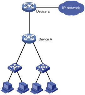
Figure 21 Network diagram after IRF deployment
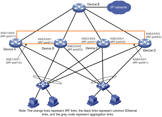
Configuration procedure
|
|
IMPORTANT: Between two neighboring IRF members, IRF links must be bound to IRF-port 1 on one member and to IRF-port 2 on the other. |
1. Configure Device A:
# Assign member ID 1 and priority 12 to Device A.
<Sysname> system-view
[Sysname] irf member 1
[Sysname] irf priority 12
# Bind Ten-GigabitEthernet 3/0/2 and Ten-GigabitEthernet 3/0/1 to IRF-port 1 and IRF-port 2, respectively.
[Sysname] irf-port 1
[Sysname-irf-port1] port group interface ten-gigabitethernet 3/0/2
[Sysname-irf-port1] quit
[Sysname] irf-port 2
[Sysname-irf-port2] port group interface ten-gigabitethernet 3/0/1
[Sysname-irf-port2] quit
# Save the configuration.
[Sysname] save
# Enable IRF mode.
[Sysname] chassis convert mode irf
The device will switch to IRF mode and reboot. You are recommended to save the current running configuration and specify the configuration file for the next startup. Continue? [Y/N]:y
Do you want to convert the content of the next startup configuration file flash:/startup.cfg to make it available in IRF mode? [Y/N]:y
Please wait...
Saving the converted configuration file to the main board succeeded.
Slot 1:
Saving the converted configuration file succeeded.
Now rebooting, please wait...
2. Configure Device B:
# Assign member ID 2 and member priority 26 to Device B.
<Sysname> system-view
[Sysname] irf member 2
[Sysname] irf priority 26
# Bind Ten-GigabitEthernet 3/0/1 and Ten-GigabitEthernet 3/0/2 to IRF-port 1 and IRF-port 2, respectively.
[Sysname] irf-port 1
[Sysname-irf-port1] port group interface ten-gigabitethernet 3/0/1
[Sysname-irf-port1] quit
[Sysname] irf-port 2
[Sysname-irf-port2] port group interface ten-gigabitethernet 3/0/2
[Sysname-irf-port2] quit
# Save the configuration.
[Sysname] save
# Connect Device B to Device A, as shown in Figure 21.
# Enable IRF mode on Device B.
[Sysname] chassis convert mode irf
The device will switch to IRF mode and reboot. You are recommended to save the current running configuration and specify the configuration file for the next startup. Continue? [Y/N]:y
Do you want to convert the content of the next startup configuration file flash:/startup.cfg to make it available in IRF mode? [Y/N]:y
Please wait...
Saving the converted configuration file to the main board succeeded.
Slot 1:
Saving the converted configuration file succeeded.
Now rebooting, please wait...
Device B and Device A form an IRF fabric after Device B reboots.
3. Configure Device C:
# Assign member ID 3 and member priority 6 to Device C.
<Sysname> system-view
[Sysname] irf member 3
[Sysname] irf priority 6
# Bind Ten-GigabitEthernet 3/0/2 and Ten-GigabitEthernet 3/0/1 to IRF-port 1 and IRF-port 2, respectively.
[Sysname] irf-port 1
[Sysname-irf-port1] port group interface ten-gigabitethernet 3/0/2
[Sysname-irf-port1] quit
[Sysname] irf-port 2
[Sysname-irf-port2] port group interface ten-gigabitethernet 3/0/1
[Sysname-irf-port2] quit
# Save the configuration.
[Sysname] save
# Connect Device C to Device B, as shown in Figure 21.
# Enable IRF mode on Device C.
[Sysname] chassis convert mode irf
The device will switch to IRF mode and reboot. You are recommended to save the current running configuration and specify the configuration file for the next startup. Continue? [Y/N]:y
Do you want to convert the content of the next startup configuration file flash:/startup.cfg to make it available in IRF mode? [Y/N]:y
Please wait...
Saving the converted configuration file to the main board succeeded.
Slot 1:
Saving the converted configuration file succeeded.
Now rebooting, please wait...
Device C reboots to join the IRF fabric.
4. Configure Device D:
# Assign member ID 4 and member priority 2 to Device D.
<Sysname> system-view
[Sysname] irf member 4
[Sysname] irf priority 2
# Bind Ten-GigabitEthernet 3/0/1 and Ten-GigabitEthernet 3/0/2 to IRF-port 1 and IRF-port 2, respectively.
[Sysname] irf-port 1
[Sysname-irf-port1] port group interface ten-gigabitethernet 3/0/1
[Sysname-irf-port1] quit
[Sysname] irf-port 2
[Sysname-irf-port2] port group interface ten-gigabitethernet 3/0/2
[Sysname-irf-port2] quit
# Save the configuration.
[Sysname] save
# Connect Device D to Device A and Device C, as shown in Figure 21.
# Enable IRF mode on Device D.
[Sysname] chassis convert mode irf
The device will switch to IRF mode and reboot. You are recommended to save the current running configuration and specify the configuration file for the next startup. Continue? [Y/N]:y
Do you want to convert the content of the next startup configuration file flash:/startup.cfg to make it available in IRF mode? [Y/N]:y
Please wait...
Saving the converted configuration file to the main board succeeded.
Slot 1:
Saving the converted configuration file succeeded.
Now rebooting, please wait...
Device D reboots to join the IRF fabric. A four-chassis IRF fabric is formed.
5. Configure LACP MAD, BFD MAD, ARP MAD, or ND MAD in the IRF fabric, as described in the previous configuration examples. (Details not shown.)
Setting up an IRF 3 system
Overview
IRF 3 integrates multiple lower-layer devices with a higher-layer IRF fabric to provide high-density, low-cost connectivity at the access layer.
In an IRF 3 system, the higher-layer IRF fabric is called the parent fabric and the lower-layer devices are called port extenders (PEXs). You can manage and configure the PEXs from the parent fabric as if they were interface cards on the parent fabric.
Typically, IRF 3 works at the access layer of data centers. As shown in Figure 22, the access layer of a network is virtualized into an IRF 3 system. The system contains one parent fabric (a two-chassis IRF fabric) and multiple PEXs to provide connectivity for servers and hosts.
Figure 22 IRF 3 application scenario
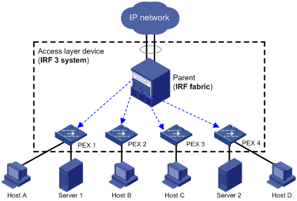
IRF 3 provides the following benefits:
· Simplified topology—Devices in an IRF 3 system appear as one node. For redundancy and load balancing, a downstream or upstream device can connect to the IRF 3 system through multichassis link aggregation. Together with link aggregation, IRF 3 creates a loop-free Layer 2 network. The spanning tree feature is not needed among devices in the IRF 3 system or on the link aggregations. IRF 3 also simplifies the Layer 3 network topology because it reduces the number of routing peers. The network topology does not change when a device is added to or removed from the IRF 3 system.
· Single point of management—An IRF 3 system is accessible at a single IP address on the network. You can use this IP address to log in through any network port to manage all the devices in the system. For an SNMP NMS, an IRF 3 system is one managed network node.
· Network scalability and resiliency—You can increase the number of ports in an IRF 3 system by adding PEXs without changing network topology.
· High availability—PEXs have multiple high-speed physical interfaces for uplink connectivity to the parent fabric. The links on these ports are aggregated and load balanced automatically.
· Decreased TCO—IRF 3 decreases hardware investments and management costs. In an IRF 3 system, the parent fabric performs all the management and routing functions, and the PEXs only forwards traffic. You can add low-performance devices as PEXs to an IRF 3 system for network scalability. In addition, PEXs can load software and synchronize configuration from the parent fabric without administrative intervention.
Network topology
The following are the methods to connect PEXs to the parent fabric:
· One tier of PEXs—Each PEX is directly connected to the parent fabric. PEXs cannot be connected to each other, as shown in Figure 23.
· Two-tier PEX stack—One tier of PEXs (tier-2 PEXs) are attached to the tier-1 PEXs (the PEXs that are directly connected to the parent fabric). The two tiers of PEXs are connected and configured to form a PEX stack. Figure 24 shows a typical PEX stack access topology.
Figure 23 IRF 3 network topology with one tier of PEXs
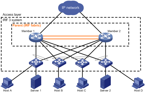
Figure 24 IRF 3 network topology (PEX stack)
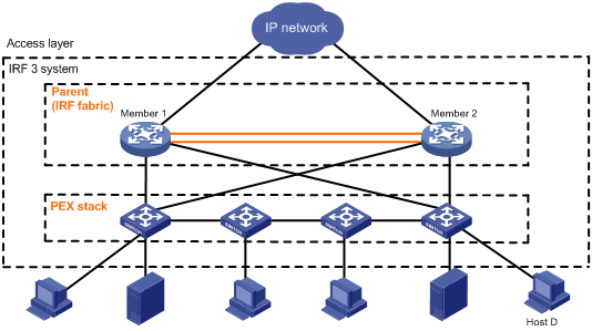
Basic concepts
IRF 3 includes IRF concepts and adds the concepts in this section. For more information about IRF concepts, see "Setting up an IRF fabric."
IRF 3 roles
The devices in an IRF 3 system have the following roles:
· Parent fabric—Higher-layer single-chassis or multichassis IRF fabric that controls the entire IRF 3 system, including PEXs. Each IRF 3 system has one parent fabric.
· Parent device—Member devices in the parent fabric.
· Master device—Controls and manages the entire IRF 3 system, including all parent devices and PEXs. The master device in the IRF fabric is also the master device for the IRF 3 system. You configure all devices (including PEXs and parent devices) from the master device.
· PEX—Operates as I/O modules of the parent fabric to receive and transmit traffic. All forwarding decisions are made on the parent fabric. Table 3 shows the operating states of PEXs.
|
State |
Description |
|
Loading |
The PEX is starting up. To avoid problems, do not reboot a PEX while it is in Loading state. |
|
Online |
The PEX has started up and registered with the parent fabric. |
|
Offline |
The PEX is offline. |
PEX port
A PEX port is a logical port created on the parent fabric for managing PEXs attached to the port.
In PEX independent access mode, you must create a unique PEX port for each PEX, and assign all physical interfaces connected to the PEX to the PEX port.
In PEX stack access mode, you must create a unique PEX port for each tier-1 PEX and its tier-2 PEX.
PEX port group
A PEX port group represents a PEX stack. The PEX ports that connect to the same PEX stack must be assigned to the same PEX port group. For example, to build the PEX stack in Figure 25, you must assign PEX port 1 and PEX port 2 to the same PEX port group.
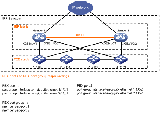
PEX physical interface
PEX physical interfaces connect PEXs and the parent fabric.
You can set up multiple PEX links between the parent fabric and a PEX. These links aggregate automatically for backup and load balancing.
On the parent fabric, you must assign the PEX physical interfaces for one PEX to the same PEX port. On a PEX, you must connect all its PEX physical interfaces to the physical interfaces in the same PEX port.
Table 4 describes the states of PEX physical interfaces.
Table 4 PEX physical interface states
|
State |
Description |
|
Forwarding |
The PEX physical interface is operating correctly and can forward data traffic. |
|
Down |
The physical link is disconnected. The PEX physical interface cannot forward any packets. |
|
Blocked |
The PEX physical interface cannot forward any packets except for IRF 3 packets. The Blocked state is a transitional state between Forwarding and Down. A PEX physical interface changes to the Blocked state in the following situations: · Incorrect physical connection: ¡ The PEX has PEX links to more than one PEX port on the parent fabric. ¡ The PEX port on the parent fabric contains physical links to more than one PEX. · The data link is forced to the Blocked state. In the startup phase, the PEX blocks a PEX physical interface if the interface's physical link is up, but it is not used for loading startup software. · The physical state of the interface is up, but the PEX link to the parent fabric has been disconnected. The PEX and the parent fabric cannot receive IRF 3 heartbeat packets from each other. |
Virtual slot number and virtual chassis
For management purposes, each PEX is assigned to a unique virtual chassis on the parent fabric. A PEX is managed as an interface module on its virtual chassis. The slot number for the PEX is fixed at 0.
The virtual chassis number and slot number are included as the first two segments of the interface numbers on the PEX. For example, a PEX has an interface numbered 1/0/1 before it is added to an IRF 3 system. The interface number changes to 100/0/0/1 after the PEX is added to chassis 100 in an IRF 3 system.
IRF 3 operating mechanisms
IRF 3 membership establishment
After you complete PEX configuration for a PEX, the master device monitors the PEX physical interfaces for the chassis number request from the PEX. The PEX uses the following process to join the IRF 3 system:
1. Virtual chassis assignment:
a. At startup, the PEX sends a chassis number request to the master device.
b. The master device assigns the user-configured chassis number to the PEX.
2. Software loading and PEX registration:
a. The PEX sends a startup software request to the master device.
b. The master device provides the correct Boot ROM and startup software images to the PEX.
c. The PEX loads the software images, and then automatically reboots to register with the master device.
3. Configuration synchronization:
a. The parent device issues its running configuration to the PEX.
b. The PEX runs with the configuration received from the master device instead of reading the configuration from its local startup configuration file.
4. PEX link maintenance:
The master device and the PEX send heartbeat packets on the PEX links to detect link failure. You can determine whether a PEX link is available by checking the state of its physical interfaces.
Configuration management
An IRF 3 system manages all its settings (including settings for PEXs) on the master device. You can configure and manage PEXs only from the master device. The running configuration on the master device has all settings in the IRF 3 system, including settings for PEXs. When a PEX reboots or is added, the master device issues its running configuration to the PEX.
Data forwarding
The PEXs do not have local forwarding capability.
The PEXs send any incoming traffic to the parent fabric. The parent fabric makes the forwarding decisions and sends the traffic to the outgoing interfaces. Figure 26 shows the data forwarding model.
Figure 26 Data forwarding model
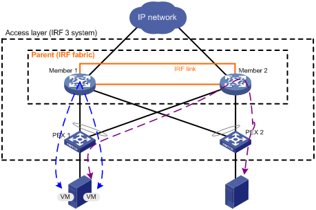
IRF fabric split handling
When the parent fabric splits, a PEX uses the same conflict handling rules as LACP MAD and BFD MAD to select one split IRF fabric as its parent fabric. After selecting one IRF fabric as the parent fabric, the PEX blocks all PEX links to other IRF fabrics.
As a best practice, use LACP MAD or BFD MAD on the parent fabric to ensure that the PEX selects the same IRF fabric to forward traffic as IRF. If any other MAD mechanisms are used, the parent fabric selected by the PEX might be placed in Recovery state.
|
|
NOTE: Ports on a PEX cannot be used for IRF MAD. When you configure MAD mechanisms, use ports on the parent fabric and devices that are not in the IRF 3 system. |
Hardware compatibility
H3C S7500E switches can only operate as parent devices. The following PEXs are available:
· S5130-EI.
· S5130-HI.
· S6300.
|
|
IMPORTANT: You can stack only the S5130-EI PEXs. |
To connect to PEXs, you must purchase any of the following modules:
To connect to PEXs, you must purchase any of the following modules:
· EC interface module: LSQM1TGS12EC0.
· SC interface modules:
¡ LSQM2GP24TSSC0.
¡ LSQM2GP44TSSC0.
¡ LSQM2GT24PTSSC0.
¡ LSQM2GT24TSSC0.
· SF interface module: LSQM2TGS16SF0.
· SG interface modules.
Configuration restrictions and guidelines
For a successful IRF 3 system setup, read the configuration restrictions and guidelines carefully before you connect and set up a PEX.
Parent fabric size restrictions
Number of member devices cannot exceed two for the parent fabric.
PEX physical interface requirements
PEX physical interface selection
Make sure the PEX physical interfaces at the two ends of a PEX link are at the same rate.
Use Table 5 to identify physical interfaces for PEX links.
Table 5 Candidate PEX physical interfaces
|
Switch model |
Candidate PEX physical interfaces |
Remarks |
|
S7500E |
Use the SFP+ and QSFP+ ports on the interface modules listed in "Hardware compatibility" for PEX links. |
If you use the SFP+ ports in a group (see "SFP+ port grouping rules") for PEX links, follow these restrictions and guidelines: · You must use all or none of the ports for PEX links. The SFP+ ports can be assigned to different PEX ports. · To shut down or bring up any SFP+ ports in the group, you must make sure all the SFP+ ports have been assigned to or removed from PEX ports. |
|
S6300 series switches |
Use the following physical interfaces for PEX links: · The highest numbered four SFP+ ports on the front panel. · QSFP+ ports on the front panel. |
Do not use both SFP+ and QSFP+ ports for PEX links. |
|
S5130-EI series switches |
Use SFP+ ports on the front panel for PEX links. |
N/A |
|
· S5130-54C-HI · S5130-54C-PWR-HI · S5130-34C-HI · S5130-30F-HI · S5130-30C-PWR-HI · S5130-30C-HI |
Use SFP+ ports on the front panel for PEX links. |
If you use an S5130-HI switch as a PEX, follow these restrictions and guidelines: · Do not install any expansion interface cards except for expansion interface cards LSWM2SP2PM and LSWM2XGT2PM. · Do not connect the switch with SFP+ DAC cables. · Do not use SFP-XG-LX220-MM1310 transceiver modules. · Do not connect ports on an expansion interface card to the parent fabric. |
SFP+ port grouping rules
The SFP+ ports on the LSQM1TGS12EC0 interface module are grouped by port number in order, starting from 1. Each group contains four ports.
The SFP+ ports on the LSQM2TGS16SF0 interface module are divided into the following groups:
· Ports 1, 2, 15, and 16.
· Ports 3 through 5.
· Ports 6 through 8.
· Ports 9 through 11.
· Ports 12 through 14.
PEX physical interface shutdown restrictions on PEXs
The shutdown command cannot be executed on any ports of PEXs for PEX links.
PEX cabling for one tier of PEXs
When you connect one tier of PEXs to the parent fabric, follow these cabling restrictions and guidelines:
· On the parent fabric side, connect a PEX port's all physical interfaces to the same PEX.
· On the PEX side, connect all its PEX physical interfaces to the physical interfaces in the same PEX port.
· Do not connect PEXs to each other.
· IRF 3 only supports one layer of PEXs. You cannot attach a lower-layer PEX to a higher-layer PEX.
· Do not attach a lower-layer network device to a PEX.
PEX cabling for PEX stack
When you connect the parent fabric and a PEX stack, follow these cabling restrictions and guidelines:
· PEXs and PEX stacks can coexist. However, PEXs of the same PEX port must use the same connection method.
· A PEX stack can contain a maximum of two tiers of PEXs. Each tier-1 PEX can be connected to a maximum of one tier-2 PEX.
· Connect PEXs in the same stack in daisy-chain topology. Do not connect PEXs of different stacks to each other.
· On the parent fabric side, connect a PEX port's all physical interfaces to the same tier-1 PEX.
· On the tier-1 PEX side, connect all its PEX physical interfaces to the physical interfaces in the same PEX port.
IRF member ID restrictions
In an IRF 3 system, change the member IDs of parent devices with caution. If the member ID of a parent device is changed, you must reconfigure the PEX port bindings on the parent device.
sFlow compatibility
sFlow is not available on PEX physical interfaces.
Cross-PEX link aggregation
Ports on PEXs of different switch series cannot be aggregated into one aggregation group.
Feature availability of PEXs
Some software features supported on the parent devices are not available for PEXs. For more information about these features, see the software release notes for the parent devices.
IRF 3 system setup and configuration task list
To set up an IRF 3 system with one tier of PEXs:
|
Tasks at a glance |
Remarks |
|
1. (Required.) Planning the IRF 3 system setup |
N/A |
|
2. (Required.) Setting up the parent fabric |
The parent fabric must be a single-chassis or multichassis IRF fabric. |
|
3. (Required.) Enabling IRF 3 capability on the parent device |
N/A |
|
4. (Required.) Configuring IRF 3 settings on the parent fabric for PEXs: b. Assigning virtual chassis numbers to one tier of PEXs c. Assigning physical interfaces to PEX ports d. Configuring PEX link load sharing mode e. Specifying startup software images for PEXs |
Specifying startup software images for PEXs is optional if the PEXs have storage media and can load PEX-capable startup software images locally. For more information about PEX software specification, see software upgrade in Fundamentals Configuration Guide. Configuring PEX link load sharing mode is optional. |
|
5. (Required.) Connecting the PEXs to the parent fabric |
Make sure the PEX cabling is consistent with the PEX physical interface assignment on the parent fabric. PEXs join the IRF 3 system when PEX links come up. To remove PEXs from the IRF 3 system, see "Removing PEXs from an IRF 3 system." |
To set up an IRF 3 system with PEX stacks:
|
Tasks at a glance |
Remarks |
|
1. (Required.) Planning the IRF 3 system setup |
N/A |
|
2. (Required.) Setting up the parent fabric |
The parent fabric must be a single-chassis or multichassis IRF fabric. |
|
3. (Required.) Enabling IRF 3 capability on the parent device |
N/A |
|
4. (Required.) Configuring IRF 3 settings on the parent fabric for PEXs: b. Assigning virtual chassis numbers to a PEX stack c. Creating a PEX port group and assigning the PEX ports of a PEX stack to the group d. Assigning physical interfaces to PEX ports e. Configuring PEX link load sharing mode f. Specifying startup software images for PEXs |
Specifying startup software images for PEXs is optional if the PEXs have storage media and can load PEX-capable startup software images locally. For more information about PEX software specification, see software upgrade in Fundamentals Configuration Guide. Configuring PEX link load sharing mode is optional. |
|
5. (Required.) Connecting the PEXs to the parent fabric |
Make sure the PEX cabling is consistent with the PEX physical interface assignment on the parent fabric. Connect PEXs to each other for the PEX stack. PEXs join the IRF 3 system when PEX links come up. To remove PEXs from the IRF 3 system, see "Removing PEXs from an IRF 3 system." |
Planning the IRF 3 system setup
Consider the following items when you plan an IRF 3 system:
· Hardware compatibility and restrictions.
· IRF 3 system size. (See "Enabling IRF 3 capability on the parent device.")
· Parent devices and PEXs.
· PEX access mode.
· PEX physical interfaces and cabling scheme.
· Virtual chassis assignment for PEXs.
The plan must meet the requirements described in "Hardware compatibility" and "Configuration restrictions and guidelines."
For more information about hardware and cabling, see the installation guide for the device.
Setting up the parent fabric
"
Enabling IRF 3 capability on the parent device
For a device to operate as a parent device, you must enable its IRF 3 capability by setting the IRF mode to enhanced or light. The IRF mode determines the number of PEXs that an IRF 3 system can contain, as shown in Table 6.
Table 6 Comparison of enhanced-mode and light-mode IRF 3 systems
|
Mode |
Maximum PEXs |
Remarks |
|
Enhanced |
60. If the IRF 3 system contains S5130-EI PEXs, the total number of PEXs cannot exceed 30. |
To use this mode, the interface modules on the parent fabric can only be any of the following modules: · EC interface modules. · SC interface modules: ¡ LSQ1QGS4SC0. ¡ LSQM2GP24TSSC0. ¡ LSQM2GP44TSSC0. ¡ LSQM2GT24PTSSC0. ¡ LSQM2GT24TSSC0. ¡ LSQM2GT48SC0. ¡ LSQM4GV48SC0. · SF interface modules. · OAP module: LSU1WCME0. Other interface modules cannot start up correctly when the parent fabric is operating in enhanced IRF mode. |
|
Light |
30 |
Make sure the parent fabric does not have member devices that are assigned the member ID 3 or 4. |
When you configure IRF mode, follow these restrictions and guidelines:
· For a success IRF merge, make sure all parent devices operate in the same IRF mode.
· Make sure no non-default MDCs are created when you set the IRF mode to enhanced or light. The irf mode { enhanced | light } command and the mdc command are mutually exclusive.
· You must set the IRF operating mode to light when using PEX stack access.
To enable IRF 3 capability:
|
Step |
Command |
Remarks |
|
1. Enter system view. |
system-view |
N/A |
|
2. Enable enhanced or light IRF mode. |
irf mode { enhanced | light } |
The default IRF mode is normal. IRF capability is enabled, and IRF 3 capability is disabled. To disable IRF 3 capability, use the following commands: · irf mode normal. · undo irf mode { enhanced | light }. |
|
3. Return to user view. |
quit |
N/A |
|
4. Save the running configuration. |
save |
N/A |
|
5. Reboot the system for the setting to take effect. |
reboot |
N/A |
Configuring IRF 3 settings on the parent fabric for PEXs
Creating PEX ports
To connect one tier of PEXs, you must create a PEX port for each PEX. To connect a PEX stack, you must create a PEX port for each tier-1 PEX and its attached tier-2 PEX.
To create a PEX port:
|
Step |
Command |
|
|
1. Enter system view. |
system-view |
N/A |
|
2. Create a PEX port and enter PEX port view. |
pex-port pex-port-id |
By default, no PEX ports have been created. You can create a maximum of 120 PEX ports. |
|
3. (Optional.) Configure a port description. |
description text |
The default PEX port description is pex-port pex-number, for example, pex-port 0002. |
Assigning virtual chassis numbers to one tier of PEXs
Perform this task if you are connecting one tier of PEXs to the parent fabric.
You must assign a unique virtual chassis number to each PEX.
You cannot change the chassis number of a PEX while it is starting up.
An operating PEX will reboot if you change or remove its chassis number.
To assign a virtual chassis number to a PEX:
|
Step |
Command |
Remarks |
|
1. Enter system view. |
system-view |
N/A |
|
2. Enter PEX port view. |
pex-port pex-port-id |
N/A |
|
3. Assign a virtual chassis number to the PEX. |
associate chassis-number |
By default, no virtual chassis numbers are assigned to PEXs. If the PEX is already assigned a chassis number, the new chassis number replaces the old number. |
Assigning virtual chassis numbers to a PEX stack
On each PEX port, you can configure one tier-1 PEX and one tier-2 PEX.
You must assign a unique virtual chassis number to each PEX.
You cannot change the chassis number of a PEX while it is starting up.
The PEX will reboot if you change or delete its virtual chassis number after the PEX has started up.
To assign a virtual chassis number to a PEX:
|
Step |
Command |
Remarks |
|
1. Enter system view. |
system-view |
N/A |
|
2. Enter PEX port view. |
pex-port pex-port-id |
N/A |
|
3. Assign a virtual chassis number to the tier-1 PEX. |
associate chassis-number |
By default, no virtual chassis numbers are assigned to PEXs. If you execute this command multiple times, the most recent configuration takes effect. |
|
4. Assign a virtual chassis number to the tier-2 PEX. |
associate order chassis-number |
By default, no virtual chassis numbers are assigned to PEXs. To change the assigned number, you must first remove the old number. |
Creating a PEX port group and assigning the PEX ports of a PEX stack to the group
To set up a PEX stack, you must assign all its PEX ports to the same PEX port group. For example, the physical topology of a PEX stack is (PEX port 1)—PEX 100—PEX 101—PEX 102—PEX 103—(PEX port 2). To set up the PEX stack, you must assign PEX port 1 and PEX port 2 to the same PEX port group.
When you assign PEX ports to a PEX port group, follow these restrictions and guidelines:
· The PEX ports must exist.
· A PEX port can be assigned only to one PEX port group.
· The assignment fails if the number of PEX ports has reached the upper limit for the PEX port group.
To create a PEX port group and assign PEX ports to the group:
|
Step |
Command |
Remarks |
|
1. Enter system view. |
system-view |
N/A |
|
2. Create a PEX port group and enter PEX port group view. |
pex-port-group group-id |
By default, no PEX port groups exist. The device supports a maximum of 60 PEX port groups. |
|
3. (Optional.) Configure a description for the PEX port group. |
description text |
By default, the description is pex-port-group group-id. For example, pex-port-group 0002. |
|
4. Assign a PEX port to the PEX port group. |
member pex-port pex-port-id |
By default, a PEX port group does not contain PEX ports. Repeat this step to assign multiple PEX ports to the PEX port group. |
Assigning physical interfaces to PEX ports
A PEX port must have a minimum of one physical interface in Forwarding state for its PEXs to communicate with the parent fabric correctly. If a PEX port has only one physical interface in Forwarding state, the attached PEXs will reboot when any of the following events occur:
· The interface is removed from the PEX port.
· The interface goes down.
For more information about physical interfaces that can be used for PEX links, see "PEX physical interface requirements."
To assign physical interfaces to a PEX port:
|
Step |
Command |
Remarks |
|
1. Enter system view. |
system-view |
N/A |
|
2. Enter interface view or interface range view. |
· Enter interface view: · Enter interface range view: |
To configure one interface, enter interface view. To configure a range of interfaces, enter interface range view. |
|
3. Shut down the physical interface or interfaces. |
shutdown |
By default, all physical interfaces are up. |
|
4. Return to system view. |
quit |
N/A |
|
5. Enter PEX port view. |
pex-port pex-port-id |
N/A |
|
6. Assign a physical interface to the PEX port. |
port group interface interface-type interface-number |
By default, a PEX port does not contain physical interfaces. Repeat this step to assign multiple physical interfaces to the PEX port. A physical interface's configuration is automatically restored to the default after you assign the interface to a PEX port. Each PEX port can have a maximum of six physical interfaces. |
|
7. Return to system view. |
quit |
N/A |
|
8. Enter interface view or interface range view. |
· Enter interface view: · Enter interface range view: |
N/A |
|
9. Bring up the physical interface or interfaces. |
undo shutdown |
N/A |
Configuring PEX link load sharing mode
On a PEX port, traffic is balanced across its physical links.
You can configure the PEX port to distribute traffic based on any combination of the following criteria:
· Source IP address.
· Source MAC address.
· Destination IP address.
· Destination MAC address.
· Ingress port.
The system displays an error message if a criteria combination is not supported.
Configure the PEX link load sharing mode for PEX links in system view or PEX port view:
· In system view, the configuration is global and takes effect on all PEX ports.
· In PEX port view, the configuration is port specific and takes effect only on the specified PEX port.
A PEX port preferentially uses the port-specific load sharing mode. If no port-specific load sharing mode is available, the PEX port uses the global load sharing mode.
Configuring the global load sharing mode
|
Step |
Command |
Remarks |
|
1. Enter system view. |
system-view |
N/A |
|
2. Configure the global PEX link load sharing mode. |
pex-port global load-sharing mode { destination-ip | destination-mac | ingress-port | source-ip | source-mac } * |
By default, the PEX link load sharing mode varies by service module. For information about the default link load sharing modes of different service modules, see device management in Fundamentals Configuration Guide. If you execute this command multiple times, the most recent configuration takes effect. |
Configuring a port-specific load sharing mode
Before you configure a port-specific load sharing mode, make sure you have bound a minimum of one physical interface to the PEX port.
To configure a port-specific load sharing mode for a PEX port:
|
Step |
Command |
Remarks |
|
1. Enter system view. |
system-view |
N/A |
|
2. Enter PEX port view. |
pex-port pex-port-id |
N/A |
|
3. Configure the port-specific load sharing mode. |
pex-port load-sharing mode { destination-ip | destination-mac | ingress-port | source-ip | source-mac } * |
By default, the PEX link load sharing mode varies by service module. For information about the default link load sharing modes of different service modules, see device management in Fundamentals Configuration Guide. If you execute this command multiple times, the most recent configuration takes effect. |
Connecting the PEXs to the parent fabric
Connect all the PEX physical interfaces to the physical interfaces assigned to the same PEX port on the parent fabric.
For more information about connection restrictions and guidelines, see "PEX cabling for one tier of PEXs" and "PEX cabling for PEX stack."
Removing PEXs from an IRF 3 system
|
Step |
Command |
Remarks |
|
1. Enter system view. |
system-view |
N/A |
|
2. Change PEXs to switch mode. |
pex working-mode switch { all | chassis chassis-number slot slot-number1 [ to slot-number2 ] } |
PEXs operate in PEX mode in the IRF 3 system. The switch mode change will take effect at reboot. To cancel the change, configure the undo pex working-mode switch { all | chassis chassis-number slot slot-number1 [ to slot-number2 ] } command before the reboot. In switch mode, PEXs operate independently from the parent fabric and cannot be managed from the parent fabric. |
|
3. Return to user view. |
quit |
N/A |
|
4. Reboot each PEX that is placed in switch mode. |
reboot chassis chassis-number |
Repeat this step to reboot all PEXs that are placed in switch mode. The devices will be removed from the IRF 3 system and operate as independent switches.
After the removed devices reboot, the mode change is included in their running configuration but not in their startup configuration files. To prevent the original mode from being restored when another reboot occurs, you must save the configuration on each removed device. |
|
5. Enter system view. |
system-view |
N/A |
|
6. Enter interface view or interface range view. |
· Enter interface view: · Enter interface range view: |
Specify all physical interfaces that are connected to the removed PEXs. |
|
7. Shut down the physical interfaces. |
shutdown |
By default, all physical interfaces are up. |
|
8. Return to system view. |
quit |
N/A |
|
9. Remove the PEX settings for a removed PEX. |
a Enter PEX port view. b Remove each physical interface from the
PEX port. c Return to system view. d Remove the PEX port. |
Repeat this step to remove the PEX settings for each removed PEX. |
|
10. Enter interface view or interface range view. |
· Enter interface view: · Enter interface range view: |
N/A |
|
11. Bring up the physical interfaces. |
undo shutdown |
N/A |
Displaying and maintaining PEXs
Execute display commands in any view.
|
Task |
Command |
|
Display PEX port information. |
display pex-port [ pex-id ] [ verbose ] |
|
Display the operating mode settings for PEXs in the IRF 3 system. |
display pex working-mode { all | chassis chassis-number slot slot-number1 [ to slot-number2 ] } |
|
Display the PEX startup software images stored on the parent fabric. |
|
|
Display PEX topology information. |
display pex-port [ pex-port-id ] topology |
For more information about the display boot-loader pex command, see Fundamentals Command Reference.
IRF 3 system configuration examples
IRF 3 system with one tier of PEXs configuration example
Network requirements
As shown in Figure 27, set up an IRF 3 system that contains a two-chassis H3C S7500E parent fabric and one tier of two S6300-52QF PEXs.
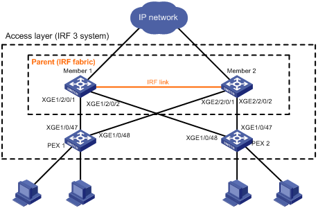
Configuration procedure
|
|
IMPORTANT: Make sure the switches to be used as PEXs run PEX-capable Boot ROM and Comware images. For software versions that support PEX, see the release notes for the switches. |
1. Configure the parent fabric:
# Set up a two-chassis S7500E IRF fabric, as described in "Setting up an IRF fabric." (Details not shown.)
# Enable enhanced IRF mode on the IRF fabric.
<Sysname> system-view
[Sysname] irf mode enhanced
[Sysname] quit
<Sysname> reboot
# Create PEX port 1 for PEX 1.
<Sysname> system-view
[Sysname] pex-port 1
# Assign virtual chassis number 100 to PEX 1.
[Sysname-pex-port1] associate 100
[Sysname-pex-port1] quit
# Shut down two ranges of ports: Ten-GigabitEthernet 1/2/0/1 through Ten-GigabitEthernet 1/2/0/4, and Ten-GigabitEthernet 2/2/0/1 through Ten-GigabitEthernet 2/2/0/4.
[Sysname] interface range ten-gigabitethernet 1/2/0/1 to ten-gigabitethernet 1/2/0/4 ten-gigabitethernet 2/2/0/1 to ten-gigabitethernet 2/2/0/4
[Sysname-if-range] shutdown
[Sysname-if-range] quit
# Assign Ten-GigabitEthernet 1/2/0/1 and Ten-GigabitEthernet 2/2/0/1 to PEX port 1.
[Sysname] pex-port 1
[Sysname-pex-port1] port group interface ten-gigabitethernet 1/2/0/1
[Sysname-pex-port1] port group interface ten-gigabitethernet 2/2/0/1
# Configure the description of PEX port 1 as connect-to-pex1.
[Sysname-pex-port1] description connect-to-pex1
[Sysname-pex-port1] quit
# Create PEX port 2 for PEX 2.
[Sysname] pex-port 2
# Assign virtual chassis number 101 to PEX 2.
[Sysname-pex-port2] associate 101
# Assign Ten-GigabitEthernet 1/2/0/2 and Ten-GigabitEthernet 2/2/0/2 to PEX port 2.
[Sysname-pex-port2] port group interface ten-gigabitethernet 1/2/0/2
[Sysname-pex-port2] port group interface ten-gigabitethernet 2/2/0/2
# Configure the description of PEX port 2 as connect-to-pex2.
[Sysname-pex-port2] description connect-to-pex2
[Sysname-pex-port2] quit
# Bind all idle physical interfaces in the same group as the PEX physical interfaces to PEX port 1 and PEX port 2.
[Sysname] pex-port 1
[Sysname-pex-port1] port group interface ten-gigabitethernet 1/2/0/3
[Sysname-pex-port1] port group interface ten-gigabitethernet 1/2/0/4
[Sysname-pex-port1] quit
[Sysname] pex-port 2
[Sysname-pex-port2] port group interface ten-gigabitethernet 2/2/0/3
[Sysname-pex-port2] port group interface ten-gigabitethernet 2/2/0/4
[Sysname-pex-port2] quit
|
|
NOTE: To shut down or bring up any SFP+ ports in a group, make sure all the SFP+ ports have been assigned to or removed from PEX ports. |
# Bring up the ports Ten-GigabitEthernet 1/2/0/1 through Ten-GigabitEthernet 1/2/0/4 and Ten-GigabitEthernet 2/2/0/1 through Ten-GigabitEthernet 2/2/0/4.
[Sysname] interface range ten-gigabitethernet 1/2/0/1 to ten-gigabitethernet 1/2/0/4 ten-gigabitethernet 2/2/0/1 to ten-gigabitethernet 2/2/0/4
[Sysname-if-range] undo shutdown
[Sysname-if-range] return
# Save the configuration.
<Sysname> save
The current configuration will be written to the device. Are you sure? [Y/N]:y
Please input the file name(*.cfg)[flash:/startup.cfg]
(To leave the existing filename unchanged, press the enter key):
flash:/startup.cfg exists, overwrite? [Y/N]:y
Validating file. Please wait...
Saved the current configuration to mainboard device successfully.
# Use FTP or TFTP to transfer PEX startup software image file to the parent device. (Details not shown.)
|
|
NOTE: You must store the image file in the root directory of a file system on the parent fabric. |
# Specify the file as the startup image file for S6300-52QF switches.
<Sysname> boot-loader pex PEX-S6300 file ipe flash:/S6300PEX.ipe main
Verifying the IPE file and the images....Done.
Decompressing file S6300PEX-CMW710-BOOT-A0045P57.bin to flash:/S6300PEX-CMW710-BOOT-A0045P57.bin.....................Done.
Decompressing file S6300PEX-CMW710-SYSTEM-A0045P57.bin to flash:/S6300PEX-CMW710-SYSTEM-A0045P57.bin............................................................................................................Done.
The system reads the images from the file after they pass verification.
2. Connect the PEXs to the parent fabric, as shown in Figure 27. (Details not shown.)
3. Use one of the following methods to change the operating mode to PEX for the switches to be used as PEXs:
¡ Change the operating mode to PEX from the EXTENDED BOOT MENU:
# Reboot PEX 1 and press Ctrl+B at the prompt. If you have set a password, you must enter the correct password to access the EXTENDED BOOT MENU.
Starting......
Press Ctrl+D to access BASIC BOOT MENU
******************************************************************************
* *
* H3C S6300-52QF BOOTROM, Version 150 *
* *
******************************************************************************
Copyright (c) 2004-2016 Hangzhou H3C Technologies Co., Ltd.
Creation Date : Jan 12 2016,19:17:00
CPU Clock Speed : 1000MHz
Memory Size : 2048MB
Flash Size : 512MB
CPLD Version : 002/002
PCB Version : Ver.B
Mac Address : 70F96D3DBB2B
PEX mode is disabled.
Press Ctrl+B to access EXTENDED BOOT MENU...0
Password recovery capability is enabled.
# In the EXTENDED BOOT MENU, press Ctrl+Y to change the operating mode to PEX.
EXTENDED BOOT MENU
1. Download image to flash
2. Select image to boot
3. Display all files in flash
4. Delete file from flash
5. Restore to factory default configuration
6. Enter BootRom upgrade menu
7. Skip current system configuration
8. Set switch startup mode
0. Reboot
Ctrl+Z: Access EXTENDED ASSISTANT MENU
Ctrl+F: Format file system
Ctrl+P: Change authentication for console login
Ctrl+Y: Change Work Mode
Ctrl+R: Download image to SDRAM and run
Enter your choice(0-8):
# Enter Y to confirm the operating mode change.
PEX mode is disabled. Are you sure you want to enable PEX mode? [Y/N]Y
Mode changed successfully
# Enter 0 in the EXTENDED BOOT MENU to reboot PEX 1.
¡ Change the operating mode to PEX from the CLI:
# Enter system view.
<Sysname> system-view
# Change the operating mode to PEX.
[Sysname] pex working-mode pex slot 1
Are you sure you want to change to the PEX mode? [Y/N]: y
If you want to change parent device to PEX mode or change PEX device to switch mode, you must reboot the device.
Reboot PEX 1 for the change to take effect.
At startup, PEX 1 loads the startup images from the parent fabric.
******************************************************************************
* *
* H3C S6300-52QF BOOTROM, Version 150 *
* *
******************************************************************************
Copyright (c) 2004-2016 Hangzhou H3C Technologies Co., Ltd.
Creation Date : Jan 12 2016,19:17:00
CPU Clock Speed : 1000MHz
Memory Size : 2048MB
Flash Size : 512MB
CPLD Version : 002/002
PCB Version : Ver.B
Mac Address : 70BAEF5CA028
PEX mode is enabled.
Press Ctrl+B to access EXTENDED BOOT MENU...0
Loading the main image files...
Loading file flash:/s5800v2_s6300pex-cmw710-system-e2130l15.bin..........................................................................................................................................................................................................................................................................Done.
Loading file flash:/s5800v2_s6300pex-cmw710-boot-e2130l15.bin........................................................................Done.
Image file flash:/s5800v2_s6300pex-cmw710-boot-e2130l15.bin is
self-decompressing...........................................................................................................................................................................................................................................................................................................................................................................................................................................................................................................................................................................................................................................................................................................................................................................Done.
System is starting...
Started downloading S6300PEX-CMW710-SYSTEM-A0045P57.bin
........................................................................................................................Done
Writing to flash
........................................................................................................................................................................................................................................................................................Done
Started downloading S6300PEX-CMW710-BOOT-A0045P57.bin
........................................................................................................................Done
Writing to flash
................................................................Done
Starting......
Press Ctrl+D to access BASIC BOOT MENU
********************************************************************************
* *
* H3C S6300-52QF BOOTROM, Version 150 *
* *
********************************************************************************
Copyright (c) 2004-2016 Hangzhou H3C Technologies Co., Ltd.
Creation Date : Jan 12 2016,19:17:00
CPU Clock Speed : 1000MHz
Memory Size : 2048MB
Flash Size : 512MB
CPLD Version : 002/002
PCB Version : Ver.B
Mac Address : 70BAEF5CA028
PEX mode is enabled.
Press Ctrl+B to access EXTENDED BOOT MENU...0
Loading the main image files...
Loading file flash:/S6300PEX-CMW710-SYSTEM-A0045P57.bin..................................................................................................................................................................................................................................................................................Done.
Loading file flash:/S6300PEX-CMW710-BOOT-A0045P57.bin..............................................................................Done.
Image file flash:/S6300PEX-CMW710-BOOT-A0045P57.bin is self-decompressing.........................................................................................................................................................................................................................................................................................................................................................................................................................................................................................................................................................................................................................................................................................................................................................Done.
System is starting...
Cryptographic algorithms tests passed.
Done.
While the PEX is starting up, the parent fabric displays messages about PEX port state changes, PEX registration, and PEX startup.
%Jan 12 10:32:43:326 2016 H3C PEX/4/PEX_LINK_BLOCK: -MDC=1-Chassis=1-Slot=2; Status of Ten-GigabitEthernet1/2/0/1 changed from down to blocked.
%Jan 12 10:32:43:326 2016 H3C PEX/4/PEX_LINK_BLOCK: -MDC=1-Chassis=2-Slot=2; Status of Ten-GigabitEthernet2/2/0/1 changed from down to blocked.
%Jan 12 10:32:43:352 2016 H3C IFNET/3/PHY_UPDOWN: -MDC=1; Ten-GigabitEthernet1/2/0/1 link status is up.
%Jan 12 10:32:43:352 2016 H3C IFNET/3/PHY_UPDOWN: -MDC=1; Ten-GigabitEthernet2/2/0/1 link status is up.
%Jan 12 10:32:43:353 2016 H3C IFNET/5/LINK_UPDOWN: -MDC=1; Line protocol on the interface Ten-GigabitEthernet1/2/0/1 is up.
%Jan 12 10:32:43:353 2016 H3C IFNET/5/LINK_UPDOWN: -MDC=1; Line protocol on the interface Ten-GigabitEthernet2/2/0/1 is up.
%Jan 12 10:32:52:753 2016 H3C PEX/5/PEX_REG_REQUEST: -MDC=1; Received a REGISTER request on PEX port 1 from PEX (chassis 100).
%Jan 12 10:32:52:766 2016 H3C DEV/4/BOARD_LOADING: -MDC=1; Board in chassis 100 slot 0 is loading software images.
%Jan 12 10:32:52:742 2016 H3C PEX/5/PEX_LINK_FORWARD: -MDC=1-Chassis=1-Slot=2; Status of Ten-GigabitEthernet1/2/0/1 changed from blocked to forwarding.
%Jan 12 10:32:52:742 2016 H3C PEX/5/PEX_LINK_FORWARD: -MDC=1-Chassis=2-Slot=2; Status of Ten-GigabitEthernet2/2/0/1 changed from blocked to forwarding.
%Jan 12 10:33:09:127 2016 H3C DEV/2/BOARD_STATE_FAULT: -MDC=1; Board state changed to Fault on chassis 100 slot 0, type is unknown.
%Jan 12 10:33:21:290 2016 H3C DEV/5/BOARD_STATE_NORMAL: -MDC=1; Board state changed to Normal on chassis 100 slot 0, type is S6300-52QF.
%Jan 12 10:33:27:754 2016 H3C PEX/5/PEX_REG_JOININ: -MDC=1; PEX (chassis 100) registered successfully on PEX port 1.
%Jan 12 10:33:28:645 2016 H3C IFNET/3/PHY_UPDOWN: -MDC=1; Pex100/0/0/51 link status is up.
%Jan 12 10:33:28:645 2016 H3C IFNET/3/PHY_UPDOWN: -MDC=1; Pex100/0/0/52 link status is up.
%Jan 12 10:33:28:647 2016 H3C IFNET/5/LINK_UPDOWN: -MDC=1; Line protocol on the interface Pex100/0/0/51 is up.
%Jan 12 10:33:28:647 2016 H3C IFNET/5/LINK_UPDOWN: -MDC=1; Line protocol on the interface Pex100/0/0/52 is up.
4. Configure PEX 2 in the same way PEX 1 is configured. (Details not shown.)
Verifying the configuration
# Verify that the IRF 3 system has been set up. You can configure the PEXs from the parent fabric if the PEXs are in Online state and each have a minimum of one PEX link in Forwarding state.
<Sysname> display pex-port verbose
PEX port 1:
Description: connnect-to-pex1
Associated chassis numbers: 1
Chassis PEX status
*100 Online
Member interfaces: 4
Member interface Status Peer interface
XGE1/2/0/1 Forwarding PEX100/0/0/51
XGE1/2/0/3 Down --
XGE1/2/0/4 Down --
XGE2/2/0/1 Forwarding PEX100/0/0/52
PEX port 2:
Description: connnect-to-pex2
Associated chassis numbers: 1
Chassis PEX status
*101 Online
Member interfaces: 4
Member interface Status Peer interface
XGE1/2/0/2 Forwarding PEX101/0/0/52
XGE2/2/0/2 Forwarding PEX101/0/0/51
XGE2/2/0/3 Down --
XGE2/2/0/4 Down --
IRF 3 system with a PEX stack configuration example
Network requirements
As shown in Figure 28, set up an IRF 3 system that contains a two-chassis parent fabric and a stack of four S5130-EI PEXs.
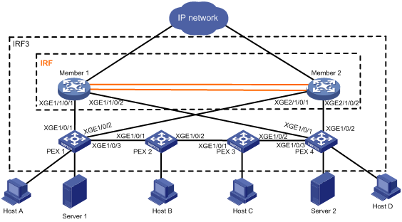
Configuration procedure
|
|
IMPORTANT: Make sure the switches to be used as PEXs run PEX-capable Boot ROM and Comware images. For software versions that support PEX, see the release notes for the switches. |
1. Configure the parent fabric:
# Set up a two-chassis IRF fabric, as described in "Setting up an IRF fabric." (Details not shown.)
# Create PEX port 1.
<Sysname> system-view
[Sysname] pex-port 1
# Assign virtual chassis number 100 to PEX 1 at tier 1.
[Sysname-pex-port1] associate 100
# Assign virtual chassis number 101 to PEX 2 (the tier-2 PEX attached to PEX 1).
[Sysname-pex-port1] associate order 101
[Sysname-pex-port1] quit
# Shut down two ranges of ports: Ten-GigabitEthernet 1/1/0/1 through Ten-GigabitEthernet 1/1/0/4, and Ten-GigabitEthernet 2/1/0/1 through Ten-GigabitEthernet 2/1/0/4.
[Sysname] interface range ten-gigabitethernet 1/1/0/1 to ten-gigabitethernet 1/1/0/4 ten-gigabitethernet 2/1/0/1 to ten-gigabitethernet 2/1/0/4
[Sysname-if-range] shutdown
[Sysname-if-range] quit
# Assign Ten-GigabitEthernet 1/1/0/1 and Ten-GigabitEthernet 2/1/0/1 to PEX port 1.
[Sysname] pex-port 1
[Sysname-pex-port1] port group interface ten-gigabitethernet 1/1/0/1
[Sysname-pex-port1] port group interface ten-gigabitethernet 2/1/0/1
[Sysname-pex-port1] quit
# Create PEX port 2.
[Sysname] pex-port 2
# Assign virtual chassis number 103 to PEX 4 at tier 1.
[Sysname-pex-port2] associate 103
# Assign virtual chassis number 102 to PEX 3 (the tier-2 PEX attached to PEX 4).
[Sysname-pex-port2] associate order 102
# Assign Ten-GigabitEthernet 1/1/0/2 and Ten-GigabitEthernet 2/1/0/2 to PEX port 2.
[Sysname-pex-port2] port group interface ten-gigabitethernet 1/1/0/2
[Sysname-pex-port2] port group interface ten-gigabitethernet 2/1/0/2
[Sysname-pex-port2] quit
# Bind all idle physical interfaces in the same group to PEX port 1 and PEX port 2.
[Sysname] pex-port 1
[Sysname-pex-port1] port group interface ten-gigabitethernet 1/1/0/3
[Sysname-pex-port1] port group interface ten-gigabitethernet 1/1/0/4
[Sysname-pex-port1] quit
[Sysname] pex-port 2
[Sysname-pex-port2] port group interface ten-gigabitethernet 2/1/0/3
[Sysname-pex-port2] port group interface ten-gigabitethernet 2/1/0/4
[Sysname-pex-port2] quit
|
|
NOTE: To shut down or bring up any SFP+ ports in a group, make sure all the SFP+ ports have been assigned to or removed from PEX ports. |
# Bring up the ports Ten-GigabitEthernet 1/1/0/1 through Ten-GigabitEthernet 1/1/0/4 and Ten-GigabitEthernet 2/1/0/1 through Ten-GigabitEthernet 2/1/0/4.
[Sysname] interface range ten-gigabitethernet 1/1/0/1 to ten-gigabitethernet 1/1/0/4 ten-gigabitethernet 2/1/0/1 to ten-gigabitethernet 2/1/0/4
[Sysname-if-range] undo shutdown
[Sysname-if-range] quit
# Create PEX port group 1.
[Sysname] pex-port-group 1
# Assign PEX port 1 and PEX port 2 to PEX port group 1.
[Sysname-pex-port-group1] member pex-port 1
[Sysname-pex-port-group1] member pex-port 2
[Sysname-pex-port1] return
# Save the configuration.
<Sysname> save
The current configuration will be written to the device. Are you sure? [Y/N]:y
Please input the file name(*.cfg)[flash:/startup.cfg]
(To leave the existing filename unchanged, press the enter key):
flash:/startup.cfg exists, overwrite? [Y/N]:y
Validating file. Please wait...
Saved the current configuration to mainboard device successfully.
# Use FTP or TFTP to transfer PEX startup software image file to the parent device. (Details not shown.)
|
|
NOTE: You must store the image file in the root directory of a file system on the parent fabric. |
# Specify the file as the startup image file for S5130-EI switches.
<Sysname> boot-loader pex PEX-S5130EI file ipe flash:/s5130EI.ipe
Verifying the IPE file and the images.........................Done.
Decompressing file pex-s5130EI-boot.bin to flash:/pex-s5130EI-boot.bin................................Done.
Decompressing file pex-s5130EI-system.bin to flash:/pex-s5130EI-system.bin...........................................................................................................................................................Done.
The system reads the images from the file after they pass verification.
2. Connect the PEXs and the parent fabric, as shown in Figure 28. (Details not shown.)
3. Use one of the following methods to change the operating mode to PEX for the candidate PEXs:
¡ Change the operating mode to PEX from the BOOT MENU:
# Reboot PEX 1 and press Ctrl+B at the prompt. If you have set a password, you must enter the correct password to access the BOOT MENU.
Starting......
Press Ctrl+D to access BASIC BOOT MENU
Press Ctrl+T to start memory test
Press Ctrl+E to start heavy memory test
********************************************************************************
* *
* H3C S5130-52S-EI BOOTROM, Version 136 *
* *
********************************************************************************
Copyright (c) 2004-2015 Hangzhou H3C Technologies Co., Ltd.
Creation Date : Jun 26 2015, 09:31:44
CPU Clock Speed : 1000MHz
Memory Size : 1024MB
Flash Size : 512MB
CPLD Version : 002
PCB Version : Ver.B
Mac Address : 586ab10acdef
PEX mode is disabled.
Press Ctrl+B to access EXTENDED BOOT MENU...0BootRom password: Not required. Please press Enter to continue.
Password recovery capability is enabled.
# In the BOOT MENU, press Ctrl+Y to change the operating mode to PEX. By default, PEX mode is disabled for the S5130-EI switch.
BOOT MENU
1. Download application file to flash
2. Select application file to boot
3. Display all files in flash
4. Delete file from flash
5. Restore to factory default configuration
6. Enter BootRom upgrade menu
7. Skip current system configuration
8. Reserved
9. Set switch startup mode
0. Reboot
Ctrl+F: Format File System
Ctrl+P: Skip Super Password
Ctrl+Y: Change Work Mode
Ctrl+R: Download application to SDRAM and Run
Ctrl+Z: Access EXTEND-ASSISTANT MENU
Enter your choice(0-9):
# Enter Y to confirm the operating mode change.
PEX mode is disabled. Are you sure you want to enable PEX mode? [Y/N]YDone!
# Enter 0 in the BOOT MENU to reboot PEX 1.
¡ Change the operating mode to PEX from the CLI:
# Enter system view.
<Sysname> system-view
# Change the operating mode to PEX.
[Sysname] pex working-mode pex slot 1
[Sysname] quit
# Reboot the PEX.
<Sysname> reboot
Reboot PEX 1 for the change to take effect.
At startup, PEX 1 loads the startup images from the parent fabric.
PEX mode is enabled.
Press Ctrl-B to enter Extended Boot menu...0......Done!
Request File: flash:/pex-s5130EI-system.bin......Done.
Loading...Done!
Loading file pex_s5130EI.cpio.gz...Done!
Request File: flash:/pex-s5130EI-boot.bin...Done.
Loading...Done!...............................................................................................................................................................................................................................Done!
System is starting...
While the PEX is starting up, the parent fabric displays messages about PEX port state changes, PEX registration, and PEX startup.
%Jan 1 11:44:04:850 2015 Sysname PEX/4/PEX_LINK_BLOCK: Status of Ten-GigabitEthernet1/1/0/1 changed from down to blocked.
%Jan 1 11:44:04:850 2015 Sysname PEX/4/PEX_LINK_BLOCK: Status of Ten-GigabitEthernet2/1/0/1 changed from down to blocked.
%Jan 1 11:44:13:483 2015 Sysname PEX/5/PEX_LINK_FORWARD: Status of Ten-GigabitEthernet1/1/0/1 changed from blocked to forwarding.
%Jan 1 11:44:13:483 2015 Sysname PEX/5/PEX_LINK_FORWARD: Status of Ten-GigabitEthernet2/1/0/1 changed from blocked to forwarding.
%Jan 1 11:44:13:518 2015 Sysname PEX/5/PEX_REG_REQUEST: Received a REGISTER request on PEX port 1 from PEX (chassis 100).
%Jan 1 11:44:14:363 2015 Sysname DEV/4/BOARD_LOADING: Board in chassis 100 is loading software images.
%Jan 1 11:44:14:365 2015 Sysname DEV/5/LOAD_FINISHED: Board in chassis 100 has finished loading software images.
%Jan 1 11:44:42:136 2015 Sysname DEV/4/BOARD_LOADING: Board in chassis 100 is loading software images.
%Jan 1 11:45:32:097 2015 Sysname DEV/5/LOAD_FINISHED: Board in chassis 100 has finished loading software images.
%Jan 1 11:48:24:339 2015 Sysname DEV/5/BOARD_STATE_NORMAL: Board state changes to NORMAL on Chassis 100, type is MAIN_BOARD_TYPE_50.
%Jan 1 11:48:29:061 2015 Sysname OPTMOD/4/MODULE_IN: -Chassis=100; Pex100/0/0/1: The transceiver is STACK_SFP_PLUS.
%Jan 1 11:48:29:061 2015 Sysname OPTMOD/4/MODULE_IN: -Chassis=100; Pex100/0/0/2: The transceiver is STACK_SFP_PLUS.
%Jan 1 11:48:37:455 2015 Sysname PEX/5/PEX_REG_JOININ: PEX (chassis 100) registered successfully on PEX port 1.
%Jan 1 11:48:42:422 2015 Sysname IFNET/3/PHY_UPDOWN: Pex100/0/0/1 link status is up.
%Jan 1 11:48:42:422 2015 Sysname IFNET/3/PHY_UPDOWN: Pex100/0/0/2 link status is up.
%Jan 1 11:48:42:430 2015 Sysname IFNET/5/LINK_UPDOWN: Line protocol on the interface Pex100/0/0/1 is up.
%Jan 1 11:48:42:430 2015 Sysname IFNET/5/LINK_UPDOWN: Line protocol on the interface Pex100/0/0/2 is up.
4. Configure PEX 2, PEX 3, and PEX 4 in the same way PEX 1 is configured. As a best practice, first configure the tier-1 PEXs and then the tier-2 PEXs. (Details not shown.)
Verifying the configuration
# Verify that the IRF 3 system has been set up. You can configure the PEXs from the parent fabric if the PEXs are in Online state and each have a minimum of one PEX link in Forwarding state.
<Sysname>dis pex-port verbose
PEX port 1:
Description: pex-port 0001
Group: 1
Associated chassis numbers: 2
Chassis PEX status
*100 Online
101 Online
Member interfaces: 2
Member interface Status Peer interface
XGE1/1/0/1 Forwarding PEX100/0/0/1
XGE2/1/0/1 Forwarding PEX100/0/0/2
PEX port 2:
Description: pex-port 0002
Group: 1
Associated chassis numbers: 2
Chassis PEX status
*103 Online
102 Online
Member interfaces: 2
Member interface Status Peer interface
XGE1/1/0/2 Forwarding PEX103/0/0/1
XGE2/1/0/2 Forwarding PEX103/0/0/2
# Verify that the PEX stack topology is correct on PEX port 1.
<Sysname> display pex-port 1 topology
PEX port 1:
PEX Neighbors Local interfaces Peer interfaces
Chassis 100 PEX port 1 PEX100/0/0/1 XGE1/1/0/1
PEX100/0/0/2 XGE2/1/0/1
Chassis 101 PEX100/0/0/3 PEX101/0/0/1
Chassis 101 Chassis 100 PEX101/0/0/1 PEX100/0/0/3
Chassis 102 PEX101/0/0/2 PEX102/0/0/1
Chassis 102 Chassis 101 PEX102/0/0/1 PEX101/0/0/2
Chassis 103 PEX102/0/0/2 PEX103/0/0/1
Chassis 103 Chassis 102 PEX103/0/0/3 PEX102/0/0/2
PEX port 2 PEX103/0/0/1 XGE1/1/0/2
PEX103/0/0/2 XGE2/1/0/2
# Verify that the PEX stack topology is correct on PEX port 2. (Details not shown.)
