- Table of Contents
- Related Documents
-
| Title | Size | Download |
|---|---|---|
| 01-VXLAN configuration | 329.32 KB |
VXLAN tunnel establishment and assignment
Assignment of traffic to VXLANs
Configuration restrictions and guidelines
Feature compatibility requirements
Assigning VXLAN tunnels to a VXLAN
Mapping an Ethernet service instance to a VSI
Enabling local-MAC change logging
Configuring static remote-MAC address entries
Enabling remote-MAC address learning
Configuring a multicast-mode VXLAN
Confining unknown-unicast floods to the local site
Configuring the destination UDP port number of VXLAN packets
Configuring VXLAN packet check
Enabling ARP flood suppression
Displaying and maintaining VXLANs
Unicast-mode VXLAN configuration example
Multicast-mode VXLAN configuration example
VXLAN overview
Virtual eXtensible LAN (VXLAN) is a MAC-in-UDP technology that provides Layer 2 connectivity between distant network sites across an IP network. VXLAN is typically used in data centers for multitenant services.
VXLAN provides the following benefits:
· Support for more virtual switched domains than VLANs—Each VXLAN is uniquely identified by a 24-bit VXLAN ID. The total number of VXLANs can reach 16777216 (224). This specification makes VXLAN a better choice than 802.1Q VLAN to isolate traffic for VMs.
· Easy deployment and maintenance—VXLAN requires deployment only on the edge devices of the transport network. Devices in the transport network perform typical Layer 3 forwarding.
The device supports only IPv4-based VXLAN. IPv6-based VXLAN is not supported.
VXLAN network model
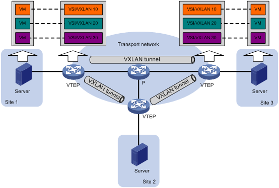
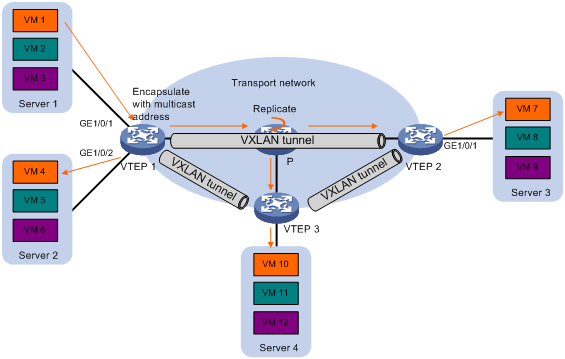
As shown in Figure 1, the transport edge devices assign VMs to different VXLANs, and then forward traffic between sites for VMs by using VXLAN tunnels.
The transport edge devices are VXLAN tunnel endpoints (VTEP). They can be servers that host VMs or independent network devices.
An H3C VTEP uses VSIs and VXLAN tunnels to provide VXLAN services.
· VSI—A virtual switching instance is a virtual Layer 2 switched domain. Each VSI provides switching services only for one VXLAN. VSIs learn MAC addresses and forward frames independently of one another. VMs in different sites have Layer 2 connectivity if they are in the same VXLAN.
· VXLAN tunnel—Logical point-to-point tunnels between VTEPs over the transport network. Each VXLAN tunnel can trunk multiple VXLANs.
VTEPs encapsulate VXLAN traffic in the VXLAN, outer UDP, and outer IP headers. The devices in the transport network forward VXLAN traffic only based on the outer IP header.
Figure 1 VXLAN network model
VXLAN packet format
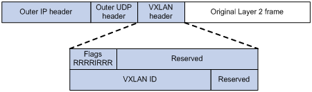
As shown in Figure 2, a VTEP encapsulates a frame in the following headers:
· 8-byte VXLAN header—VXLAN information for the frame.
? Flags—If the I bit is 1, the VXLAN ID is valid. If the I bit is 0, the VXLAN ID is invalid. All other bits are reserved and set to 0.
? 24-bit VXLAN ID—Identifies the VXLAN of the frame. It is also called the virtual network identifier (VNI).
· 8-byte outer UDP header for VXLAN—The default VXLAN destination UDP port number is 4789.
· 20-byte outer IP header—Valid addresses of VTEPs or VXLAN multicast groups on the transport network. Devices in the transport network forward VXLAN packets based on the outer IP header.
Figure 2 VXLAN packet format
Working mechanisms
The VTEP uses the following process to forward an inter-site frame:
1. Assigns the frame to its matching VXLAN if the frame is sent between sites.
2. Performs MAC learning on the VXLAN's VSI.
3. Forwards the frame.
This section describes this process in detail. For intra-site frames in a VSI, the system performs typical Layer 2 forwarding, and it processes 802.1Q VLAN tags as described in "Access modes of VSIs."
VXLAN tunnel establishment and assignment
To provide Layer 2 connectivity for a VXLAN between two sites, you must create a VXLAN tunnel between the sites and assign the tunnel to the VXLAN.
Assignment of traffic to VXLANs
Traffic from the local site to a remote site
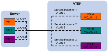
The VTEP uses an Ethernet service instance to match a list of VLANs on a site-facing interface. The VTEP assigns customer traffic to a VXLAN by mapping the Ethernet service instance to a VSI. An Ethernet service instance is identical to an attachment circuit (AC) in L2VPN.
As shown in Figure 3, Ethernet service instance 1 matches VLAN 2 and is mapped to VSI A (VXLAN 10). When a frame from VLAN 2 arrives, the VTEP assigns the frame to VXLAN 10, and looks up VSI A's MAC address table for the outgoing interface.
Figure 3 Identifying traffic from the local site
Traffic from a remote site to the local site
When a frame arrives at a VXLAN tunnel, the VTEP uses the VXLAN ID in the frame to identify its VXLAN.
MAC learning
The VTEP performs source MAC learning on the VSI as a Layer 2 switch.
· For traffic from the local site to the remote site, the VTEP learns the source MAC address before VXLAN encapsulation.
· For traffic from the remote site to the local site, the VTEP learns the source MAC address after removing the VXLAN header.
A VSI's MAC address table includes the following types of MAC address entries:
· Local MAC—Dynamic MAC entries learned from the local site. The outgoing interfaces are site-facing interfaces on which the MAC addresses are learned. VXLAN does not support manual local-MAC entries.
· Remote MAC—MAC entries learned from a remote site, including static, dynamic, and OpenFlow MAC entries. The outgoing interfaces for the MAC addresses are VXLAN tunnel interfaces.
? Static—Manually added MAC entries.
? Dynamic—MAC entries learned in the data plane from incoming traffic on VXLAN tunnels. The learned MAC addresses are contained in the inner Ethernet header.
? OpenFlow—MAC entries issued by a remote controller through OpenFlow.
For a remote address, the manual static entry has higher priority than the dynamic entry.
Traffic forwarding
The VTEP uses the following processes to forward traffic:
· Unicast process—Applies to destination-known unicast traffic.
· Flood process—Applies to multicast, broadcast, and unknown unicast traffic.
When the VTEP forwards VXLAN traffic, it processes the 802.1Q tag in the inner Ethernet header depending on the VSI access mode (VLAN or Ethernet mode). In VLAN access mode, sites can use different VLANs to provide the same service. For more information, see "Access modes of VSIs."
Unicast
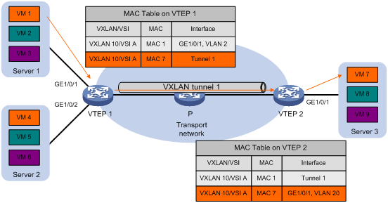
The following process (see Figure 4) applies to a known unicast frame between sites:
1. The source VTEP encapsulates the Ethernet frame in the VXLAN/UDP/IP header.
In the outer IP header, the source IP address is the source VTEP's VXLAN tunnel source IP address. The destination IP address is the VXLAN tunnel destination IP address.
2. The source VTEP forwards the encapsulated packet out of the outgoing VXLAN tunnel interface found in the VSI's MAC address table.
3. The intermediate transport devices (P devices) forward the frame to the destination VTEP by using the outer IP header.
4. The destination VTEP removes the headers on top of the inner Ethernet frame. It then performs MAC address table lookup in the VXLAN's VSI to forward the frame out of the matching outgoing interface.
Flood
The VTEP floods a broadcast, multicast, or unknown unicast frame to all site-facing interfaces and VXLAN tunnels in the VXLAN, except for the incoming interface.
VXLAN supports the following modes for flood traffic:
· Unicast mode—Also called head-end replication. The source VTEP replicates the flood frame, and then sends one replica to the destination IP address of each VXLAN tunnel in the VXLAN. See Figure 5.
· Multicast mode—Also called tandem replication. The source VTEP sends the flood frame in a multicast VXLAN packet destined for a multicast group address. Transport network devices replicate and forward the packet to remote VTEPs based on their multicast forwarding entries. See Figure 6.
Each destination VTEP floods the inner Ethernet frame to all the site-facing interfaces in the VXLAN. To avoid loops, the destination VTEPs do not flood the frame to VXLAN tunnels.

Access modes of VSIs
The access mode of a VSI determines how the VTEP processes the 802.1Q VLAN tags in the Ethernet frames.
· VLAN access mode—Ethernet frames received from or sent to the local site must contain 802.1Q VLAN tags.
? For an Ethernet frame received from the local site, the VTEP removes all its 802.1Q VLAN tags before forwarding the frame.
? For an Ethernet frame destined for the local site, the VTEP adds 802.1Q VLAN tags to the frame before forwarding the frame.
In VLAN access mode, VXLAN packets sent between sites do not contain 802.1Q VLAN tags. You can use different 802.1Q VLANs to provide the same service in different sites.
· Ethernet access mode—The VTEP does not process the 802.1Q VLAN tags of Ethernet frames received from or sent to the local site.
? For an Ethernet frame received from the local site, the VTEP forwards the frame with the 802.1Q VLAN tags intact.
? For an Ethernet frame destined for the local site, the VTEP forwards the frame without adding 802.1Q VLAN tags.
In Ethernet access mode, VXLAN packets sent between VXLAN sites contain 802.1Q VLAN tags. You must use the same VLAN to provide the same service between sites.
ARP flood suppression
ARP flood suppression reduces ARP request broadcasts by enabling the VTEP to reply to ARP requests on behalf of VMs.
As shown in Figure 7, this feature snoops ARP packets to populate the ARP flood suppression table with local and remote MAC addresses. If an ARP request has a matching entry, the VTEP replies to the request on behalf of the VM. If no match is found, the VTEP floods the request to both local and remote sites.
Figure 7 ARP flood suppression
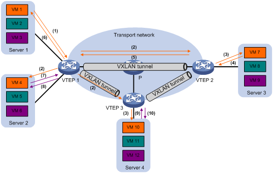
ARP flood suppression uses the following workflow:
1. VM 1 sends an ARP request to obtain the MAC address of VM 7.
2. VTEP 1 creates a suppression entry for VM 1, and floods the ARP request in the VXLAN.
3. VTEP 2 and VTEP 3 de-encapsulate the ARP request. The VTEPs create a suppression entry for VM 1, and broadcast the request in the local site.
4. VM 7 sends an ARP reply.
5. VTEP 2 creates a suppression entry for VM 7 and forwards the ARP reply to VTEP 1.
6. VTEP 1 de-encapsulates the ARP reply, creates a suppression entry for VM 7, and forwards the ARP reply to VM 1.
7. VM 4 sends an ARP request to obtain the MAC address of VM 1 or VM 7.
8. VTEP 1 creates a suppression entry for VM 4 and replies to the ARP request.
9. VM 10 sends an ARP request to obtain the MAC address of VM 1.
10. VTEP 3 creates a suppression entry for VM 10 and replies to the ARP request.
Protocols and standards
IETF draft, draft-mahalingam-dutt-dcops-vxlan-04
Configuring VXLANs
Configuration restrictions and guidelines
For VXLANs to operate correctly, follow the restrictions and guidelines in this section.
Hardware restrictions
When you configure VXLANs, follow these hardware restrictions:
· VXLAN transport-facing interfaces must be on the LSQM1SRP8X2QE0 MPU.
· VXLAN site-facing interfaces must be on the following modules:
? MPU: LSQM1SRP8X2QE0.
? EC interface module: LSQM1TGS12EC0.
? SC interface modules:
- LSQM2GP24TSSC0.
- LSQM2GP44TSSC0.
- LSQM2GT24PTSSC0.
- LSQM2GT24TSSC0.
- LSQM2GT48SC0.
- LSQM4GV48SC0.
· If the device is operating in IRF mode, make sure the IRF physical interfaces are on the LSQM1SRP8X2QE0 MPU. For more information about the IRF mode and IRF physical interfaces, see IRF in Virtual Technologies Configuration Guide.
Feature compatibility requirements
When you use VXLAN in conjunction with other features, follow these restrictions and guidelines:
· If multiple VXLAN tunnels share a transport-facing interface, make sure the VXLAN tunnels use the same VLAN interface for forwarding.
· Do not configure EVI or MPLS settings on VXLANs. For more information about EVI and MPLS, see EVI Configuration Guide and MPLS Configuration Guide.
· A site-facing interface does not support Layer 3 multicast if Ethernet service instances are configured on the interface.
· You must disable the spanning tree protocol (undo stp enable) on a site-facing interface if Ethernet service instances are configured on it.
· For a multicast-mode VXLAN to forward traffic correctly, do not configure VXLANs or VXLAN tunnels on transport network devices.
VXLAN configuration task list
|
Tasks at a glance |
Remarks |
|
(Required.) Creating a VXLAN on a VSI |
N/A |
|
(Required.) Configuring a VXLAN tunnel |
N/A |
|
(Required.) Assigning VXLAN tunnels to a VXLAN |
To extend a VXLAN to remote sites, you must assign VXLAN tunnels to the VXLAN. |
|
(Required.) Mapping an Ethernet service instance to a VSI |
Perform this task to assign customer traffic to VXLANs. |
|
(Optional.) Managing MAC address entries |
N/A |
|
(Optional.) Configuring a multicast-mode VXLAN |
By default, the VTEP floods VXLAN traffic in unicast mode. If the network is multicast dense, configure the VTEP to flood VXLAN traffic in multicast mode. |
|
(Optional.) Confining unknown-unicast floods to the local site |
N/A |
|
(Optional.) Configuring the destination UDP port number of VXLAN packets |
N/A |
|
(Optional.) Configuring VXLAN packet check |
Perform this task to check the 802.1Q VLAN tags in the inner Ethernet header of incoming VXLAN packets. |
|
(Optional.) Enabling ARP flood suppression |
N/A |
Creating a VXLAN on a VSI
|
Step |
Command |
Remarks |
|
1. Enter system view. |
system-view |
N/A |
|
2. Enable L2VPN. |
l2vpn enable |
By default, L2VPN is disabled. |
|
3. Create a VSI and enter VSI view. |
vsi vsi-name |
By default, no VSIs are created. |
|
4. (Optional.) Configure a VSI description. |
description text |
By default, a VSI does not have a description. |
|
5. Enable the VSI. |
undo shutdown |
By default, a VSI is enabled. |
|
6. (Optional.) Set the MTU for the VSI. |
mtu mtu |
The default MTU is 1500 bytes for a VSI. |
|
7. (Optional.) Enable MAC address learning for the VSI. |
mac-learning enable |
By default, MAC address learning is enabled for a VSI. The device does not support disabling MAC address learning for a VXLAN VSI. The undo mac-learning enable command does not take effect on VXLAN VSIs. |
|
8. Create a VXLAN and enter VXLAN view. |
vxlan vxlan-id |
By default, no VXLANs are created. You can create only one VXLAN on a VSI. The VXLAN ID must be unique for each VSI. |
Configuring a VXLAN tunnel
This task provides basic VXLAN tunnel configuration. For more information about tunnel configuration and commands, see Layer 3—IP Services Configuration Guide and Layer 3—IP Services Command Reference.
To configure a VXLAN tunnel:
|
Step |
Command |
Remarks |
|
1. Enter system view. |
system-view |
N/A |
|
2. Specify a global source address for VXLAN tunnels. |
tunnel global source-address ip-address |
By default, no global source address is specified for VXLAN tunnels. A VXLAN tunnel uses the global source address if you do not specify a source interface or source address for the tunnel. |
|
3. (Optional.) Specify the reserved VXLAN. |
reserved vxlan vxlan-id |
By default, no VXLAN has been reserved. If BFD is enabled on VXLAN tunnels, you must reserve a VXLAN for BFD sessions to come up. |
|
1. Create a VXLAN tunnel interface and enter tunnel interface view. |
interface tunnel tunnel-number mode vxlan |
By default, no tunnel interfaces exist. The endpoints of a tunnel must use the same tunnel mode. |
|
2. Specify a source IP address or source interface for the tunnel. |
source { ipv4-address | interface-type interface-number } |
By default, no source IP address or source interface is specified for a tunnel. This step specifies the source IP address in the outer IP header of tunneled VXLAN packets. If an interface is specified, its primary IP address is used. For a multicast-mode VXLAN, the source IP address cannot be a loopback address, and the source interface cannot be a loopback interface. |
|
3. Specify a destination IP address for the tunnel. |
destination ipv4-address |
By default, no destination IP address is specified for a tunnel. Specify the remote VTEP's IP address. This IP address will be the destination IP address in the outer IP header of tunneled VXLAN packets. As a best practice, do not configure multiple VXLAN tunnels to use the same source and destination IP addresses. |
|
4. (Optional.) Enable BFD on the tunnel. |
tunnel bfd enable destination-mac mac-address |
By default, BFD is disabled on a tunnel. Enable BFD on both ends of a VXLAN tunnel for quick link connectivity detection. The VTEPs periodically send BFD single-hop control packets to each other through the VXLAN tunnel. A VTEP sets the tunnel state to Defect if it has not received control packets from the remote end for 5 seconds. In this situation, the tunnel interface state is still Up. The tunnel state will change from Defect to Up if the VTEP can receive BFD control packets again. |
Assigning VXLAN tunnels to a VXLAN
To provide Layer 2 connectivity for a VXLAN between two sites, you must assign the VXLAN tunnel between the sites to the VXLAN.
You can assign multiple VXLAN tunnels to a VXLAN, and configure a VXLAN tunnel to trunk multiple VXLANs. For a unicast-mode VXLAN, the system floods unknown unicast, multicast, and broadcast traffic to each tunnel associated with the VXLAN.
To assign VXLAN tunnels to a VXLAN:
|
Step |
Command |
Remarks |
|
5. Enter system view. |
system-view |
N/A |
|
6. Enter VSI view. |
vsi vsi-name |
N/A |
|
7. Enter VXLAN view. |
vxlan vxlan-id |
N/A |
|
8. Assign VXLAN tunnels to the VXLAN. |
tunnel { tunnel-number | all } |
By default, a VXLAN does not contain any VXLAN tunnels. For full Layer 2 connectivity in the VXLAN, make sure the VXLAN contains the VXLAN tunnel between each pair of sites in the VXLAN. |
Mapping an Ethernet service instance to a VSI
An Ethernet service instance matches a list of VLANs on a site-facing interface. The VTEP assigns customer traffic from the VLANs to a VXLAN by mapping the Ethernet service instance to a VSI.
An Ethernet service instance can contain only one match criterion. To change the match criterion, you must remove the original criterion first. When you remove the match criterion in an Ethernet service instance, the mapping between the service instance and the VSI is removed automatically.
If an Ethernet service instance contains the encapsulation default match criterion, traffic is matched as follows:
· The service instance matches any frames if it is the only instance on the interface.
· The service instance matches frames that do not match any other service instance if multiple instances exist on the interface.
To map an Ethernet service instance to a VSI:
|
Step |
Command |
Remarks |
|
1. Enter system view. |
system-view |
N/A |
|
2. Enter Layer 2 Ethernet interface view or Layer 2 aggregate interface view. |
· interface interface-type interface-number · interface bridge-aggregation interface-number |
N/A |
|
3. Configure the port link type. |
port link-type { access | trunk | hybrid } |
The default port link type is access. |
|
4. Assign the interface to C-VLANs. |
· Access link type: · Trunk link type: · Hybrid link type: |
Make sure you have created the C-VLANs. |
|
5. Create an Ethernet service instance and enter Ethernet service instance view. |
service-instance instance-id |
By default, no Ethernet service instances exist. |
|
6. Configure a frame match criterion. |
· Match frames that do not match any other
service instance on the interface: · Match any 802.1Q tagged or untagged frames: · Match frames tagged with the specified outer 802.1Q
VLAN ID: · Match frames tagged with the specified outer
and inner 802.1Q VLAN IDs: |
By default, an Ethernet service instance does not contain a frame match criterion. To match frames from a VLAN correctly, make sure you have created the VLAN and assigned the interface to the VLAN. To match untagged frames when the VLAN access mode is used, you must use the encapsulation untagged command. |
|
7. Map the Ethernet service instance to a VSI. |
xconnect vsi vsi-name [ access-mode { ethernet | vlan } ] |
By default, an Ethernet service instance is not mapped to any VSI. If you set the match criterion to default or tagged, you must specify the Ethernet access mode. If you do not specify an access mode, the default VLAN access mode is used. |
Managing MAC address entries
With VXLAN, local MAC addresses are learned dynamically. You can log MAC changes, but you cannot manually add local MAC addresses.
Remote-MAC address entries include the following types:
· Manually created static entries.
· Dynamic entries learned in the data plane.
· MAC entries issued by a remote controller through OpenFlow.
Enabling local-MAC change logging
Local-MAC change logging enables the VXLAN module to send a log message to the information center when a local MAC address is added or removed.
With the information center, you can set log message filtering and output rules, including output destinations. For more information about configuring the information center, see Network Management and Monitoring Configuration Guide.
To enable local-MAC change logging:
|
Step |
Command |
Remarks |
|
1. Enter system view. |
system-view |
N/A |
|
2. Enable local-MAC change logging. |
vxlan local-mac report |
By default, local-MAC change logging is disabled. |
Configuring static remote-MAC address entries
|
Step |
Command |
Remarks |
|
1. Enter system view. |
system-view |
N/A |
|
2. Add a static remote entry. |
mac-address static mac-address interface tunnel tunnel-number vsi vsi-name |
By default, VXLAN VSIs do not have static remote-MAC address entries. For the setting to take effect, make sure the VSI's VXLAN has been created and specified on the VXLAN tunnel. |
Enabling remote-MAC address learning
|
Step |
Command |
Remarks |
|
1. Enter system view. |
system-view |
N/A |
|
2. Enable remote-MAC address learning. |
undo vxlan tunnel mac-learning disable |
By default, remote-MAC address learning is enabled. When network attacks occur, disable remote-MAC address learning to prevent the device from learning incorrect remote MAC addresses. |
Configuring a multicast-mode VXLAN
For a multicast-mode VXLAN to flood traffic, you must perform the following tasks in addition to multicast-mode configuration:
· Enable IP multicast routing on all VTEPs and transport network devices.
· Configure IGMP and a multicast routing protocol on transport network devices. A VTEP can be both a multicast source and multicast group member. As a best practice, use BIDIR-PIM.
To configure a multicast-mode VXLAN:
|
Step |
Command |
Remarks |
|
1. Enter system view. |
system-view |
N/A |
|
2. Enable multicast routing. |
multicast routing |
By default, multicast routing is disabled. |
|
3. Return to system view. |
quit |
N/A |
|
4. Enter VSI view. |
vsi vsi-name |
N/A |
|
5. Enter VXLAN view. |
vxlan vxlan-id |
N/A |
|
6. Assign a multicast group address for flood traffic, and specify a source IP address for multicast VXLAN packets. |
group group-address source source-address |
By default, a VXLAN uses unicast mode for flood traffic. No multicast group address or source IP address is specified for multicast VXLAN packets. You must assign all VTEPs in a multicast-mode VXLAN to the same multicast group. For traffic to be forwarded correctly, you must use the source IP address of an up VXLAN tunnel as the source IP address for multicast VXLAN packets. If the VXLAN has multiple VXLAN tunnels, the tunnels must use the same source IP address. For VXLANs that use the same multicast group address, you must configure the same source IP address for their multicast VXLAN packets. |
|
7. Enter the view of the interface that provides the source IP address for multicast VXLAN packets. |
interface interface-type interface-number |
The source source-address option in the group command specifies the source IP address of multicast VXLAN packets. |
|
8. Enable the IGMP host function. |
igmp host enable |
By default, the IGMP host function is disabled on an interface. The IGMP host function enables the interface to send IGMP reports in response to IGMP queries before it can receive traffic from the multicast group. |
Confining unknown-unicast floods to the local site
By default, the VTEP floods unknown unicast frames received from the local site to the following interfaces in the frame's VXLAN:
· All site-facing interfaces except for the incoming interface.
· All VXLAN tunnel interfaces.
To confine unknown-unicast floods to site-facing interfaces for a VXLAN:
|
Step |
Command |
Remarks |
|
|
1. Enter system view. |
system-view |
N/A |
|
|
2. Enter VSI view. |
vsi vsi-name |
N/A |
|
|
3. Disable the VSI to flood unknown unicast traffic to VXLAN tunnel interfaces. |
flooding disable |
By default, unknown unicast traffic is flooded to all interfaces in the VXLAN, except for the incoming interface. |
|
|
4. (Optional.) Enable selective flood for a MAC address. |
selective-flooding mac-address mac-address |
By default, selective flood is disabled. Use this feature to exclude a remote MAC address from the flood suppression done by using the flooding disable command. The VTEP will flood the frames destined for the specified MAC address to remote sites when unknown-unicast floods are confined to the local site. |
|
Configuring the destination UDP port number of VXLAN packets
|
Step |
Command |
Remarks |
|
|
1. Enter system view. |
system-view |
N/A |
|
|
2. Configure a destination UDP port for VXLAN packets. |
vxlan udp-port port-number |
By default, the destination UDP port number is 4789 for VXLAN packets. You must configure the same destination UDP port number on all VTEPs in a VXLAN. |
|
Configuring VXLAN packet check
The device checks the inner Ethernet header of each VXLAN packet for 802.1Q VLAN tags. If the header contains 802.1Q VLAN tags, the device drops the packet.
If a remote VTEP uses the Ethernet access mode, its VXLAN packets might contain 802.1Q VLAN tags. To prevent the local VTEP from dropping the VXLAN packets, do not execute the vxlan invalid-vlan-tag discard command on the local VTEP.
The access mode is configurable by using the xconnect vsi command.
To configure VXLAN packet check:
|
Step |
Command |
Remarks |
|
1. Enter system view. |
system-view |
N/A |
|
2. Enable the VTEP to drop VXLAN packets that have 802.1Q VLAN tags in the inner Ethernet header. |
vxlan invalid-vlan-tag discard |
By default, the VTEP does not check the inner Ethernet header for 802.1Q VLAN tags. |
Enabling ARP flood suppression
Use ARP flood suppression to reduce ARP request broadcasts.
The aging timer is fixed at 25 minutes for ARP flood suppression entries. If the suppression table is full, the VTEP stops learning new entries. For the VTEP to learn new entries, you must wait for old entries to age out, or use the reset arp suppression command to clear the table.
If the flooding disable command is executed on a VSI that is enabled with ARP flood suppression, follow these restrictions and guidelines:
· As a best practice, set the MAC aging timer to a higher value than the aging timer for ARP flood suppression entries on all VTEPs. This setting prevents the traffic blackhole that occurs when a MAC address entry ages out before its ARP flood suppression entry ages out.
· You must use the mac-address static command to manually add remote MAC address entries on each VTEP.
To set the MAC aging timer, use the mac-address timer command.
When you configure ARP flood suppression on a multicast-mode VXLAN, follow these restrictions and guidelines:
· Make sure ARP flood suppression is enabled or disabled across the VTEPs in the VXLAN.
· Do not enable ARP flood suppression if the VXLAN contains third-party VTEPs.
To enable ARP flood suppression:
|
Step |
Command |
Remarks |
|
1. Enter system view. |
system-view |
N/A |
|
2. Enter VSI view. |
vsi vsi-name |
N/A |
|
3. Enable ARP flood suppression. |
arp suppression enable |
By default, ARP flood suppression is disabled. |
Displaying and maintaining VXLANs
Execute display commands in any view and reset commands in user view.
|
Task |
Command |
|
Display ARP flood suppression entries on VSIs (in standalone mode). |
display arp suppression vsi [ name vsi-name ] [ slot slot-number ] [ count ] |
|
Display ARP flood suppression entries on VSIs (in IRF mode). |
display arp suppression vsi [ name vsi-name ] [ chassis chassis-number slot slot-number ] [ count ] |
|
Display MAC address entries for VSIs. |
display l2vpn mac-address [ vsi vsi-name ] [ dynamic ] [ count ] |
|
Display information about Ethernet service instances. |
display l2vpn service-instance [ interface interface-type interface-number [ service-instance instance-id ] ] [ verbose ] |
|
Display information about VSIs. |
display l2vpn vsi [ name vsi-name ] [ verbose ] |
|
Display information about the multicast groups that contain IGMP host-enabled interfaces. |
display igmp host group [ group-address | interface interface-type interface-number ] [ verbose ] |
|
Display information about tunnel interfaces. |
display interface [ tunnel [ number ] ] [ brief [ description | down ] ] |
|
Display VXLAN tunnel information for VXLANs. |
display vxlan tunnel [ vxlan vxlan-id ] |
|
Clear ARP flood suppression entries on VSIs. |
reset arp suppression vsi [ name vsi-name ] |
|
Clear dynamic MAC address entries on VSIs. |
reset l2vpn mac-address [ vsi vsi-name ] |
|
Clear packet statistics on VSIs. |
reset l2vpn statistics vsi [ name vsi-name ] |
For more information about the display interface tunnel command, see tunneling commands in Layer 3—IP Services Command Reference.
VXLAN configuration examples
Unicast-mode VXLAN configuration example
Network requirements
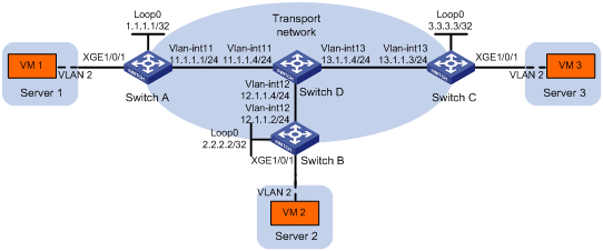
As shown in Figure 8:
· Configure VXLAN 10 as a unicast-mode VXLAN on Switch A, Switch B, and Switch C to provide Layer 2 connectivity for the VMs across the network sites.
· Manually establish VXLAN tunnels and assign the tunnels to VXLAN 10.
· Enable remote-MAC address learning.
Configuration procedure
1. Configure IP addresses and unicast routing settings:
# Assign IP addresses to interfaces, as shown in Figure 8. (Details not shown.)
# Configure OSPF on all transport network switches (Switches A through D). (Details not shown.)
2. Configure Switch A:
# Enable L2VPN.
<SwitchA> system-view
[SwitchA] l2vpn enable
# Create the VSI vpna and VXLAN 10.
[SwitchA] vsi vpna
[SwitchA-vsi-vpna] vxlan 10
[SwitchA-vsi-vpna-vxlan10] quit
[SwitchA-vsi-vpna] quit
# Assign an IP address to Loopback 0. The IP address will be used as the source IP address of the VXLAN tunnels to Switch B and Switch C.
[SwitchA] interface loopback0
[SwitchA-Loopback0] ip address 1.1.1.1 255.255.255.255
[SwitchA-Loopback0] quit
# Create a VXLAN tunnel to Switch B. The tunnel interface name is Tunnel 1.
[SwitchA] interface tunnel 1 mode vxlan
[SwitchA-Tunnel1] source 1.1.1.1
[SwitchA-Tunnel1] destination 2.2.2.2
[SwitchA-Tunnel1] quit
# Create a VXLAN tunnel to Switch C. The tunnel interface name is Tunnel 2.
[SwitchA] interface tunnel 2 mode vxlan
[SwitchA-Tunnel2] source 1.1.1.1
[SwitchA-Tunnel2] destination 3.3.3.3
[SwitchA-Tunnel2] quit
# Assign Tunnel 1 and Tunnel 2 to VXLAN 10.
[SwitchA] vsi vpna
[SwitchA-vsi-vpna] vxlan 10
[SwitchA-vsi-vpna-vxlan10] tunnel 1
[SwitchA-vsi-vpna-vxlan10] tunnel 2
[SwitchA-vsi-vpna-vxlan10] quit
[SwitchA-vsi-vpna] quit
# Create VLAN 2, and assign the site-facing interface Ten-GigabitEthernet 1/0/1 to VLAN 2.
[SwitchA] vlan 2
[SwitchA-vlan2] quit
[SwitchA] interface ten-gigabitethernet 1/0/1
[SwitchA-Ten-GigabitEthernet1/0/1] port link-type trunk
[SwitchA-Ten-GigabitEthernet1/0/1] port trunk permit vlan 2
# On Ten-GigabitEthernet 1/0/1, create Ethernet service instance 1000 to match VLAN 2.
[SwitchA-Ten-GigabitEthernet1/0/1] service-instance 1000
[SwitchA-Ten-GigabitEthernet1/0/1-srv1000] encapsulation s-vid 2
# Map Ethernet service instance 1000 to the VSI vpna.
[SwitchA-Ten-GigabitEthernet1/0/1-srv1000] xconnect vsi vpna
[SwitchA-Ten-GigabitEthernet1/0/1-srv1000] quit
[SwitchA-Ten-GigabitEthernet1/0/1] quit
3. Configure Switch B:
# Enable L2VPN.
<SwitchB> system-view
[SwitchB] l2vpn enable
# Create the VSI vpna and VXLAN 10.
[SwitchB] vsi vpna
[SwitchB-vsi-vpna] vxlan 10
[SwitchB-vsi-vpna-vxlan10] quit
[SwitchB-vsi-vpna] quit
# Assign an IP address to Loopback 0. The IP address will be used as the source IP address of the VXLAN tunnels to Switch A and Switch C.
[SwitchB] interface loopback0
[SwitchB-Loopback0] ip address 2.2.2.2 255.255.255.255
[SwitchB-Loopback0] quit
# Create a VXLAN tunnel to Switch A. The tunnel interface name is Tunnel 2.
[SwitchB] interface tunnel 2 mode vxlan
[SwitchB-Tunnel2] source 2.2.2.2
[SwitchB-Tunnel2] destination 1.1.1.1
[SwitchB-Tunnel2] quit
# Create a VXLAN tunnel to Switch C. The tunnel interface name is Tunnel 3.
[SwitchB] interface tunnel 3 mode vxlan
[SwitchB-Tunnel3] source 2.2.2.2
[SwitchB-Tunnel3] destination 3.3.3.3
[SwitchB-Tunnel3] quit
# Assign Tunnel 2 and Tunnel 3 to VXLAN 10.
[SwitchB] vsi vpna
[SwitchB-vsi-vpna] vxlan 10
[SwitchB-vsi-vpna-vxlan10] tunnel 2
[SwitchB-vsi-vpna-vxlan10] tunnel 3
[SwitchB-vsi-vpna-vxlan10] quit
[SwitchB-vsi-vpna] quit
# Create VLAN 2, and assign the site-facing interface Ten-GigabitEthernet 1/0/1 to VLAN 2.
[SwitchB] vlan 2
[SwitchB-vlan2] quit
[SwitchB] interface ten-gigabitethernet 1/0/1
[SwitchB-Ten-GigabitEthernet1/0/1] port link-type trunk
[SwitchB-Ten-GigabitEthernet1/0/1] port trunk permit vlan 2
# On Ten-GigabitEthernet 1/0/1, create Ethernet service instance 1000 to match VLAN 2.
[SwitchB-Ten-GigabitEthernet1/0/1] service-instance 1000
[SwitchB-Ten-GigabitEthernet1/0/1-srv1000] encapsulation s-vid 2
# Map Ethernet service instance 1000 to the VSI vpna.
[SwitchB-Ten-GigabitEthernet1/0/1-srv1000] xconnect vsi vpna
[SwitchB-Ten-GigabitEthernet1/0/1-srv1000] quit
[SwitchB-Ten-GigabitEthernet1/0/1] quit
4. Configure Switch C:
# Enable L2VPN.
<SwitchC> system-view
[SwitchC] l2vpn enable
# Create the VSI vpna and VXLAN 10.
[SwitchC] vsi vpna
[SwitchC-vsi-vpna] vxlan 10
[SwitchC-vsi-vpna-vxlan10] quit
[SwitchC-vsi-vpna] quit
# Assign an IP address to Loopback 0. The IP address will be used as the source IP address of the VXLAN tunnels to Switch A and Switch B.
[SwitchC] interface loopback0
[SwitchC-Loopback0] ip address 3.3.3.3 255.255.255.255
[SwitchC-Loopback0] quit
# Create a VXLAN tunnel to Switch A. The tunnel interface name is Tunnel 1.
[SwitchC] interface tunnel 1 mode vxlan
[SwitchC-Tunnel1] source 3.3.3.3
[SwitchC-Tunnel1] destination 1.1.1.1
[SwitchC-Tunnel1] quit
# Create a VXLAN tunnel to Switch B. The tunnel interface name is Tunnel 3.
[SwitchC] interface tunnel 3 mode vxlan
[SwitchC-Tunnel3] source 3.3.3.3
[SwitchC-Tunnel3] destination 2.2.2.2
[SwitchC-Tunnel3] quit
# Assign Tunnel 1 and Tunnel 3 to VXLAN 10.
[SwitchC] vsi vpna
[SwitchC-vsi-vpna] vxlan 10
[SwitchC-vsi-vpna-vxlan10] tunnel 1
[SwitchC-vsi-vpna-vxlan10] tunnel 3
[SwitchC-vsi-vpna-vxlan10] quit
[SwitchC-vsi-vpna] quit
# Create VLAN 2, and assign the site-facing interface Ten-GigabitEthernet 1/0/1 to VLAN 2.
[SwitchC] vlan 2
[SwitchC-vlan2] quit
[SwitchC] interface ten-gigabitethernet 1/0/1
[SwitchC-Ten-GigabitEthernet1/0/1] port link-type trunk
[SwitchC-Ten-GigabitEthernet1/0/1] port trunk permit vlan 2
# On Ten-GigabitEthernet 1/0/1, create Ethernet service instance 1000 to match VLAN 2.
[SwitchC-Ten-GigabitEthernet1/0/1] service-instance 1000
[SwitchC-Ten-GigabitEthernet1/0/1-srv1000] encapsulation s-vid 2
# Map Ethernet service instance 1000 to the VSI vpna.
[SwitchC-Ten-GigabitEthernet1/0/1-srv1000] xconnect vsi vpna
[SwitchC-Ten-GigabitEthernet1/0/1-srv1000] quit
[SwitchC-Ten-GigabitEthernet1/0/1] quit
Verifying the configuration
1. Verify the VXLAN settings on the VTEPs. This example uses Switch A.
# Verify that the VXLAN tunnel interfaces on the VTEP are up.
[SwitchA] display interface tunnel 1
Tunnel1
Current state: UP
Line protocol state: UP
Description: Tunnel1 Interface
Bandwidth: 64kbps
Maximum Transmit Unit: 64000
Internet protocol processing: disabled
Last clearing of counters: Never
Tunnel source 1.1.1.1, destination 2.2.2.2
Tunnel protocol/transport UDP_VXLAN/IP
# Verify that the VXLAN tunnels have been assigned to the VXLAN.
[SwitchA] display l2vpn vsi verbose
VSI Name: vpna
VSI Index : 0
VSI State : Up
MTU : 1500
Bandwidth : -
Broadcast Restrain : -
Multicast Restrain : -
Unknown Unicast Restrain: -
MAC Learning : Enabled
MAC Table Limit : -
Drop Unknown : -
Flooding : Enabled
VXLAN ID : 10
Tunnels:
Tunnel Name Link ID State Type Flooding proxy
Tunnel1 0x5000001 Up Manual Disabled
Tunnel2 0x5000002 Up Manual Disabled
ACs:
AC Link ID State
XGE1/0/1 srv1000 0 Up
# Verify that the VTEP has learned the MAC addresses of remote VMs.
<SwitchA> display l2vpn mac-address
MAC Address State VSI Name Link ID/Name Aging
cc3e-5f9c-6cdb Dynamic vpna Tunnel1 Aging
cc3e-5f9c-23dc Dynamic vpna Tunnel2 Aging
--- 2 mac address(es) found ---
2. Verify that VM 1, VM 2, and VM 3 can ping each other. (Details not shown.)
Multicast-mode VXLAN configuration example
Network requirements
As shown in Figure 9:
· Configure VXLAN 10 as a multicast-mode VXLAN on Switch A, Switch B, and Switch C to provide Layer 2 connectivity for the VMs across the network sites.
· Manually establish VXLAN tunnels and assign the tunnels to VXLAN 10.
· Enable remote-MAC address learning.
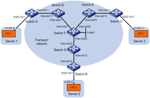
Table 1 IP address assignment
|
Device |
Interface |
IP address |
Device |
Interface |
IP address |
|
Switch A: |
|
|
Switch C: |
|
|
|
|
VLAN-interface 11 |
11.1.1.1/24 |
|
VLAN-interface 13 |
13.1.1.3/24 |
|
Switch D: |
|
|
Switch E: |
|
|
|
|
VLAN-interface 11 |
11.1.1.4/24 |
|
VLAN-interface 13 |
13.1.1.5/24 |
|
|
VLAN-interface 21 |
21.1.1.4/24 |
|
VLAN-interface 23 |
23.1.1.5/24 |
|
Switch F: |
|
|
Switch G: |
|
|
|
|
VLAN-interface 21 |
21.1.1.6/24 |
|
VLAN-interface 12 |
12.1.1.7/24 |
|
|
VLAN-interface 22 |
22.1.1.6/24 |
|
VLAN-interface 22 |
22.1.1.7/24 |
|
|
VLAN-interface 23 |
23.1.1.6/24 |
Switch B: |
|
|
|
|
Loop0 |
6.6.6.6/32 |
|
VLAN-interface 12 |
12.1.1.2/24 |
Configuration procedure
1. Configure IP addresses and unicast routing settings:
# Assign IP addresses to interfaces, as shown in Figure 9. (Details not shown.)
# Configure OSPF on all transport network switches (Switches A through G). (Details not shown.)
2. Configure Switch A:
# Enable L2VPN.
<SwitchA> system-view
[SwitchA] l2vpn enable
# Enable IP multicast routing.
[SwitchA] multicast routing
[SwitchA-mrib] quit
# Create the VSI vpna and VXLAN 10.
[SwitchA] vsi vpna
[SwitchA-vsi-vpna] vxlan 10
[SwitchA-vsi-vpna-vxlan10] quit
[SwitchA-vsi-vpna] quit
# Assign an IP address to VLAN-interface 11, and enable the IGMP host function on the interface. This interface's IP address will be the source IP address of VXLAN packets sent by the VTEP.
[SwitchA] interface vlan-interface 11
[SwitchA-Vlan-interface11] ip address 11.1.1.1 24
[SwitchA-Vlan-interface11] igmp host enable
[SwitchA-Vlan-interface11] quit
# Create a VXLAN tunnel to Switch B. The tunnel interface name is Tunnel 1.
[SwitchA] interface tunnel 1 mode vxlan
[SwitchA-Tunnel1] source 11.1.1.1
[SwitchA-Tunnel1] destination 12.1.1.2
[SwitchA-Tunnel1] quit
# Create a VXLAN tunnel to Switch C. The tunnel interface name is Tunnel 2.
[SwitchA] interface tunnel 2 mode vxlan
[SwitchA-Tunnel2] source 11.1.1.1
[SwitchA-Tunnel2] destination 13.1.1.3
[SwitchA-Tunnel2] quit
# Assign Tunnel 1 and Tunnel 2 to VXLAN 10.
[SwitchA] vsi vpna
[SwitchA-vsi-vpna] vxlan 10
[SwitchA-vsi-vpna-vxlan10] tunnel 1
[SwitchA-vsi-vpna-vxlan10] tunnel 2
# Configure the multicast group address and source IP address for multicast VXLAN packets.
[SwitchA-vsi-vpna-vxlan10] group 225.1.1.1 source 11.1.1.1
[SwitchA-vsi-vpna-vxlan10] quit
[SwitchA-vsi-vpna] quit
# Create VLAN 2, and assign the site-facing interface Ten-GigabitEthernet 1/0/1 to VLAN 2.
[SwitchA] vlan 2
[SwitchA-vlan2] quit
[SwitchA] interface ten-gigabitethernet 1/0/1
[SwitchA-Ten-GigabitEthernet1/0/1] port link-type trunk
[SwitchA-Ten-GigabitEthernet1/0/1] port trunk permit vlan 2
# On Ten-GigabitEthernet 1/0/1, create Ethernet service instance 1000 to match VLAN 2.
[SwitchA-Ten-GigabitEthernet1/0/1] service-instance 1000
[SwitchA-Ten-GigabitEthernet1/0/1-srv1000] encapsulation s-vid 2
# Map Ethernet service instance 1000 to the VSI vpna.
[SwitchA-Ten-GigabitEthernet1/0/1-srv1000] xconnect vsi vpna
[SwitchA-Ten-GigabitEthernet1/0/1-srv1000] quit
[SwitchA-Ten-GigabitEthernet1/0/1] quit
3. Configure Switch B:
# Enable L2VPN.
<SwitchB> system-view
[SwitchB] l2vpn enable
# Enable IP multicast routing.
[SwitchB] multicast routing
[SwitchB-mrib] quit
# Create the VSI vpna and VXLAN 10.
[SwitchB] vsi vpna
[SwitchB-vsi-vpna] vxlan 10
[SwitchB-vsi-vpna-vxlan10] quit
[SwitchB-vsi-vpna] quit
# Assign an IP address to VLAN-interface 12, and enable the IGMP host function on the interface. This interface's IP address will be the source IP address of VXLAN packets sent by the VTEP.
[SwitchB] interface vlan-interface 12
[SwitchB-Vlan-interface12] ip address 12.1.1.2 24
[SwitchB-Vlan-interface12] igmp host enable
[SwitchB-Vlan-interface12] quit
# Create a VXLAN tunnel to Switch A. The tunnel interface name is Tunnel 2.
[SwitchB] interface tunnel 2 mode vxlan
[SwitchB-Tunnel2] source 12.1.1.2
[SwitchB-Tunnel2] destination 11.1.1.1
[SwitchB-Tunnel2] quit
# Create a VXLAN tunnel to Switch C. The tunnel interface name is Tunnel 3.
[SwitchB] interface tunnel 3 mode vxlan
[SwitchB-Tunnel3] source 12.1.1.2
[SwitchB-Tunnel3] destination 13.1.1.3
[SwitchB-Tunnel3] quit
# Assign Tunnel 2 and Tunnel 3 to VXLAN 10.
[SwitchB] vsi vpna
[SwitchB-vsi-vpna] vxlan 10
[SwitchB-vsi-vpna-vxlan10] tunnel 2
[SwitchB-vsi-vpna-vxlan10] tunnel 3
# Configure the VXLAN multicast group address and the source IP address for VXLAN packets.
[SwitchB-vsi-vpna-vxlan10] group 225.1.1.1 source 12.1.1.2
[SwitchB-vsi-vpna-vxlan10] quit
[SwitchB-vsi-vpna] quit
# Create VLAN 2, and assign the site-facing interface Ten-GigabitEthernet 1/0/1 to VLAN 2.
[SwitchB] vlan 2
[SwitchB-vlan2] quit
[SwitchB] interface ten-gigabitethernet 1/0/1
[SwitchB-Ten-GigabitEthernet1/0/1] port link-type trunk
[SwitchB-Ten-GigabitEthernet1/0/1] port trunk permit vlan 2
# On Ten-GigabitEthernet 1/0/1, create Ethernet service instance 1000 to match VLAN 2.
[SwitchB-Ten-GigabitEthernet1/0/1] service-instance 1000
[SwitchB-Ten-GigabitEthernet1/0/1-srv1000] encapsulation s-vid 2
# Map Ethernet service instance 1000 to the VSI vpna.
[SwitchB-Ten-GigabitEthernet1/0/1-srv1000] xconnect vsi vpna
[SwitchB-Ten-GigabitEthernet1/0/1-srv1000] quit
[SwitchB-Ten-GigabitEthernet1/0/1] quit
4. Configure Switch C:
# Enable L2VPN.
<SwitchC> system-view
[SwitchC] l2vpn enable
# Enable IP multicast routing.
[SwitchC] multicast routing
[SwitchC-mrib] quit
# Create the VSI vpna and VXLAN 10.
[SwitchC] vsi vpna
[SwitchC-vsi-vpna] vxlan 10
[SwitchC-vsi-vpna-vxlan10] quit
[SwitchC-vsi-vpna] quit
# Assign an IP address to VLAN-interface 13, and enable the IGMP host function on the interface. This interface's IP address will be the source IP address of VXLAN packets sent by the VTEP.
[SwitchC] interface vlan-interface 13
[SwitchC-Vlan-interface13] ip address 13.1.1.3 24
[SwitchC-Vlan-interface13] igmp host enable
[SwitchC-Vlan-interface13] quit
# Create a VXLAN tunnel to Switch A. The tunnel interface name is Tunnel 1.
[SwitchC] interface tunnel 1 mode vxlan
[SwitchC-Tunnel1] source 13.1.1.3
[SwitchC-Tunnel1] destination 11.1.1.1
[SwitchC-Tunnel1] quit
# Create a VXLAN tunnel to Switch B. The tunnel interface name is Tunnel 3.
[SwitchC] interface tunnel 3 mode vxlan
[SwitchC-Tunnel3] source 13.1.1.3
[SwitchC-Tunnel3] destination 12.1.1.2
[SwitchC-Tunnel3] quit
# Assign Tunnel 1 and Tunnel 3 to VXLAN 10.
[SwitchC] vsi vpna
[SwitchC-vsi-vpna] vxlan 10
[SwitchC-vsi-vpna-vxlan10] tunnel 1
[SwitchC-vsi-vpna-vxlan10] tunnel 3
# Configure the multicast group address and source IP address for VXLAN multicast packets.
[SwitchC-vsi-vpna-vxlan10] group 225.1.1.1 source 13.1.1.3
[SwitchC-vsi-vpna-vxlan10] quit
[SwitchC-vsi-vpna] quit
# Create VLAN 2, and assign the site-facing interface Ten-GigabitEthernet 1/0/1 to VLAN 2.
[SwitchC] vlan 2
[SwitchC-vlan2] quit
[SwitchC] interface ten-gigabitethernet 1/0/1
[SwitchC-Ten-GigabitEthernet1/0/1] port link-type trunk
[SwitchC-Ten-GigabitEthernet1/0/1] port trunk permit vlan 2
# On Ten-GigabitEthernet 1/0/1, create Ethernet service instance 1000 to match VLAN 2.
[SwitchC-Ten-GigabitEthernet1/0/1] service-instance 1000
[SwitchC-Ten-GigabitEthernet1/0/1-srv1000] encapsulation s-vid 2
# Map Ethernet service instance 1000 to the VSI vpna.
[SwitchC-Ten-GigabitEthernet1/0/1-srv1000] xconnect vsi vpna
[SwitchC-Ten-GigabitEthernet1/0/1-srv1000] quit
[SwitchC-Ten-GigabitEthernet1/0/1] quit
5. Configure Switch D:
# Enable IP multicast routing.
<SwitchD> system-view
[SwitchD] multicast routing
[SwitchD-mrib] quit
# Enable IGMP and PIM-SM on VLAN-interface 11.
[SwitchD] interface vlan-interface 11
[SwitchD-Vlan-interface11] igmp enable
[SwitchD-Vlan-interface11] pim sm
[SwitchD-Vlan-interface11] quit
# Enable PIM-SM on VLAN-interface 21.
[SwitchD] interface vlan-interface 21
[SwitchD-Vlan-interface21] pim sm
[SwitchD-Vlan-interface21] quit
# Enable BIDIR-PIM.
[SwitchD] pim
[SwitchD-pim] bidir-pim enable
[SwitchD-pim] quit
6. Configure Switch E:
# Enable IP multicast routing.
<SwitchE> system-view
[SwitchE] multicast routing
[SwitchE-mrib] quit
# Enable IGMP and PIM-SM on VLAN-interface 13.
[SwitchE] interface vlan-interface 13
[SwitchE-Vlan-interface13] igmp enable
[SwitchE-Vlan-interface13] pim sm
[SwitchE-Vlan-interface13] quit
# Enable PIM-SM on VLAN-interface 23.
[SwitchE] interface vlan-interface 23
[SwitchE-Vlan-interface23] pim sm
[SwitchE-Vlan-interface23] quit
# Enable BIDIR-PIM.
[SwitchE] pim
[SwitchE-pim] bidir-pim enable
[SwitchE-pim] quit
7. Configure Switch F:
# Enable IP multicast routing.
<SwitchF> system-view
[SwitchF] multicast routing
[SwitchF-mrib] quit
# Enable PIM-SM on VLAN-interface 21, VLAN-interface 22, and VLAN-interface 23.
[SwitchF] interface vlan-interface 21
[SwitchF-Vlan-interface21] pim sm
[SwitchF-Vlan-interface21] quit
[SwitchF] interface vlan-interface 22
[SwitchF-Vlan-interface22] pim sm
[SwitchF-Vlan-interface22] quit
[SwitchF] interface vlan-interface 23
[SwitchF-Vlan-interface23] pim sm
[SwitchF-Vlan-interface23] quit
# Enable BIDIR-PIM.
[SwitchF] pim
[SwitchF-pim] bidir-pim enable
# Configure VLAN-interface 22 as a candidate-BSR, and configure Loopback 0 as a candidate-RP for BIDIR-PIM.
[SwitchF-pim] c-bsr 22.1.1.6
[SwitchF-pim] c-rp 6.6.6.6 bidir
[SwitchF-pim] quit
8. Configure Switch G:
# Enable IP multicast routing.
<SwitchG> system-view
[SwitchG] multicast routing
[SwitchG-mrib] quit
# Enable IGMP and PIM-SM on VLAN-interface 12.
[SwitchG] interface vlan-interface 12
[SwitchG-Vlan-interface12] igmp enable
[SwitchG-Vlan-interface12] pim sm
[SwitchG-Vlan-interface12] quit
# Enable PIM-SM on VLAN-interface 22.
[SwitchG] interface vlan-interface 22
[SwitchG-Vlan-interface22] pim sm
[SwitchG-Vlan-interface22] quit
# Enable BIDIR-PIM.
[SwitchG] pim
[SwitchG-pim] bidir-pim enable
[SwitchG-pim] quit
Verifying the configuration
1. Verify the VXLAN settings on the VTEPs. This example uses Switch A.
# Verify that the VXLAN tunnel interfaces on the VTEP are up.
[SwitchA] display interface tunnel 1
Tunnel1
Current state: UP
Line protocol state: UP
Description: Tunnel1 Interface
Bandwidth: 64kbps
Maximum Transmit Unit: 64000
Internet protocol processing: disabled
Last clearing of counters: Never
Tunnel source 11.1.1.1, destination 12.1.1.2
Tunnel protocol/transport UDP_VXLAN/IP
# Verify that the VXLAN tunnels have been assigned to the VXLAN.
[SwitchA] display l2vpn vsi verbose
VSI Name: vpna
VSI Index : 0
VSI State : Up
MTU : 1500
Bandwidth : -
Broadcast Restrain : -
Multicast Restrain : -
Unknown Unicast Restrain: -
MAC Learning : Enabled
MAC Table Limit : -
Drop Unknown : -
Flooding : Enabled
VXLAN ID : 10
Tunnels:
Tunnel Name Link ID State Type Flooding proxy
Tunnel1 0x5000001 Up Manual Disabled
Tunnel2 0x5000002 Up Manual Disabled
MTunnel1 0x6000000 Up Auto Disabled
ACs:
AC Link ID State
XGE1/0/1 srv1000 0 Up
# Verify that the VTEP has learned the MAC addresses of remote VMs.
<SwitchA> display l2vpn mac-address
MAC Address State VSI Name Link ID/Name Aging
cc3e-5f9c-6cdb Dynamic vpna Tunnel1 Aging
cc3e-5f9c-23dc Dynamic vpna Tunnel2 Aging
--- 2 mac address(es) found ---
# Verify that the VTEP has joined the VXLAN multicast group on VLAN-interface 11.
<SwitchA> display igmp host group
IGMP host groups in total: 1
Vlan-interface11(11.1.1.1):
IGMP host groups in total: 1
Group address Member state Expires
225.1.1.1 Idle Off
2. Verify that VM 1, VM 2, and VM 3 can ping each other. (Details not shown.)