- Table of Contents
-
- 06 IP Multicast Configuration Guide
- 00-Preface
- 01-Multicast Overview
- 02-IGMP snooping configuration
- 03-PIM snooping configuration
- 04-Multicast VLAN configuration
- 05-Multicast routing and forwarding configuration
- 06-IGMP configuration
- 07-PIM configuration
- 08-MSDP configuration
- 09-Multicast VPN configuration
- 10-MLD snooping configuration
- 11-IPv6 PIM snooping configuration
- 12-IPv6 multicast VLAN configuration
- 13-IPv6 multicast routing and forwarding configuration
- 14-MLD configuration
- 15-IPv6 PIM configuration
- Related Documents
-
| Title | Size | Download |
|---|---|---|
| 05-Multicast routing and forwarding configuration | 285.47 KB |
Contents
Configuring multicast routing and forwarding
Multicast forwarding across unicast subnets
Configuring multicast routing and forwarding
Configuring static multicast routes
Specifying the longest prefix match principle
Configuring multicast load splitting
Configuring a multicast forwarding boundary
Configuring static multicast MAC address entries
Configuring multicast forwarding among sub-VLANs of a super VLAN
Displaying and maintaining multicast routing and forwarding
Multicast forwarding over a GRE tunnel
Troubleshooting multicast routing and forwarding
Static multicast route failure
Overview
The following tables are involved in multicast routing and forwarding:
· Multicast routing table of each multicast routing protocol, such as the PIM routing table.
· General multicast routing table that summarizes multicast routing information generated by different multicast routing protocols. The multicast routing information from multicast sources to multicast groups are stored in a set of (S, G) routing entries.
· Multicast forwarding table that guides multicast forwarding. The optimal routing entries in the multicast routing table are added to the multicast forwarding table.
The term "interface" in this chapter collectively refers to VLAN interfaces and Layer 3 Ethernet interfaces. You can set an Ethernet port as a Layer 3 interface by using the port link-mode route command (see Layer 2—LAN Switching Configuration Guide).
RPF check mechanism
A multicast routing protocol relies on the existing unicast routes, MBGP routes, or static multicast routes to create multicast routing entries. When creating multicast routing entries, the multicast routing protocol uses the reverse path forwarding (RPF) check to ensure the multicast data delivery along the correct paths. The RPF check also helps avoid data loops.
A multicast routing protocol uses the following tables to perform an RPF check:
· Unicast routing table—Contains unicast routing information.
· Static multicast routing table—Contains RPF routes that are manually configured.
A static multicast routing table is used for RPF check rather than multicast routing.
RPF check process
A router performs the RPF check on a multicast packet as follows:
1. The router chooses an optimal route back to the packet source separately from the unicast routing table and the static multicast routing table.
A "packet source" means different things in different situations:
¡ For a packet that travels along the SPT, the packet source is the multicast source.
¡ For a packet that travels along the RPT, the packet source is the RP.
¡ For a bootstrap message from the BSR, the packet source is the BSR.
For more information about the concepts of SPT, RPT, source-side RPT, RP, and BSR, see "Configuring PIM."
2. The router selects one of the two optimal routes as the RPF route as follows:
¡ If the router uses the longest prefix match principle, the route with a higher subnet mask becomes the RPF route. If the routes have the same mask, the route with a higher route preference becomes the RPF route. If the routes have the same route preference, the unicast route becomes the RPF route.
For more information about the route preference, see Layer 3—IP Routing Configuration Guide.
¡ If the router does not use the longest prefix match principle, the route with a higher route preference becomes the RPF route. If the routes have the same preference, the unicast route becomes the RPF route.
The RPF route determines the RPF interface and the RPF neighbor.
¡ If the RPF route is a unicast route, the outgoing interface of the route is the RPF interface, and the next hop is the RPF neighbor.
¡ If the RPF route is a static multicast route, the RPF interface and RPF neighbor are those specified in the route.
3. The router checks whether the packet arrived at the RPF interface. If yes, the RPF check succeeds and the packet is forwarded. If not, the RPF check fails and the packet is discarded.
RPF check implementation in multicast
Implementing an RPF check on each received multicast packet brings a big burden to the router. The use of a multicast forwarding table is the solution to this issue. When the router creates a multicast forwarding entry for an (S, G) packet, it sets the RPF interface of the packet as the incoming interface of the (S, G) forwarding entry. After the router receives another (S, G) packet, it looks up the multicast forwarding table for the matching (S, G) entry:
· If no match is found, the router first determines the RPF route back to the packet source. Then, it creates a forwarding entry with the RPF interface as the incoming interface and performs one of the following actions:
¡ If the receiving interface is the RPF interface, the RPF check succeeds and the router forwards the packet out of all the outgoing interfaces.
¡ If the receiving interface is not the RPF interface, the RPF check fails and the router discards the packet.
· If a match is found and the receiving interface is the incoming interface of the forwarding entry, the router forwards the packet out of all the outgoing interfaces.
· If a match is found but the receiving interface is not the incoming interface of the forwarding entry, the router first determines the RPF route back to the packet source. Then, the router performs one of the following actions:
¡ If the RPF interface is the incoming interface, it means that the forwarding entry is correct but the packet traveled along a wrong path. The packet fails the RPF check, and the router discards the packet.
¡ If the RPF interface is not the incoming interface, it means that the forwarding entry has expired. The router replaces the incoming interface with the RPF interface and matches the receiving interface against the RPF interface. If the receiving interface is the RPF interface, the router forwards the packet out of all outgoing interfaces. Otherwise, it discards the packet.
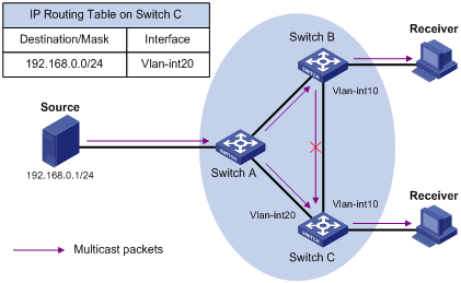
As shown in Figure 1, assume that unicast routes are available in the network and no static multicast routes have been configured on Switch C. Multicast packets travel along the SPT from the multicast source to the receivers. The multicast forwarding table on Switch C contains the (S, G) entry, with VLAN-interface 20 as the incoming interface.
· If a multicast packet arrives at Switch C on VLAN-interface 20, the receiving interface is the incoming interface of the (S, G) entry. Switch C forwards the packet out of all outgoing interfaces.
· If a multicast packet arrives at Switch C on VLAN-interface 10, the receiving interface is not the incoming interface of the (S, G) entry. Switch C looks up its unicast routing table and finds that the outgoing interface to the source (the RPF interface) is VLAN-interface 20. In this case, the (S, G) entry is correct, but the packet traveled along a wrong path. The packet fails the RPF check, and Switch C discards the packet.
Static multicast routes
Depending on the application environment, a static multicast route can change an RPF route or create an RPF route.
Changing an RPF route
Typically, the topology structure of a multicast network is the same as that of a unicast network, and multicast traffic follows the same transmission path as unicast traffic does. You can configure a static multicast route for a multicast source to change the RPF route. As a result, the router creates a transmission path for multicast traffic that is different from the transmission path for unicast traffic.
Figure 2 Changing an RPF route
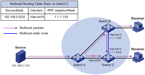
As shown in Figure 2, when no static multicast route is configured, Switch C's RPF neighbor on the path back to the source is Switch A. The multicast data from the source travels through Switch A to Switch C. You can configure a static multicast route on Switch C and specify its RPF neighbor on the route back to the source as Switch B. Then, the multicast data from the source travels along the path: Switch A to Switch B and then to Switch C.
Creating an RPF route
When a unicast route is blocked, multicast forwarding might be stopped due to lack of an RPF route. In this case, you can create an RPF route by configuring a static multicast route for a multicast source. Then, a multicast routing entry is created to guide multicast forwarding.
Figure 3 Creating an RPF route
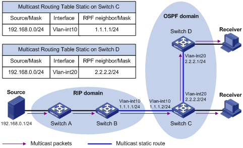
As shown in Figure 3, the RIP domain and the OSPF domain are unicast isolated from each other. The receiver hosts in the OSPF domain cannot receive the multicast packets from the multicast source in the RIP domain. You can configure static multicast routes on Switch C and Switch D and specify Switch B and Switch C as the RPF neighbors of Switch C and Switch D, respectively. Then, the receiver hosts can receive the multicast data from the multicast source.
|
|
NOTE: A static multicast route is effective only on the multicast router on which it is configured, and will not be advertised throughout the network or redistributed to other routers. |
Multicast forwarding across unicast subnets
Routers forward the multicast data from a multicast source hop by hop along the forwarding tree, but some routers might not support multicast protocols in a network. When the multicast data is forwarded to a router that does not support IP multicast, the forwarding path is blocked. In this case, you can enable multicast forwarding across two unicast subnets by establishing a tunnel between the routers at the edges of the two unicast subnets.
Figure 4 Multicast data transmission through a tunnel
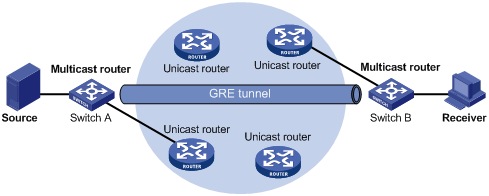
As shown in Figure 4, a tunnel is established between the multicast routers Switch A and Switch B. Switch A encapsulates the multicast data in unicast IP packets, and forwards them to Switch B across the tunnel through unicast routers. Then, Switch B strips off the unicast IP header and continues to forward the multicast data to the receiver.
To use this tunnel only for multicast traffic, configure the tunnel as the outgoing interface only for multicast routes.
Configuration task list
|
Tasks at a glance |
|
(Required.) Enabling IP multicast routing |
|
(Optional.) Configuring multicast routing and forwarding · (Optional.) Configuring static multicast routes · (Optional.) Specifying the longest prefix match principle · (Optional.) Configuring multicast load splitting · (Optional.) Configuring a multicast forwarding boundary · (Optional.) Configuring static multicast MAC address entries · (Optional.) Configuring multicast forwarding among sub-VLANs of a super VLAN |
|
|
NOTE: The device can route and forward multicast data only through the primary IP addresses of interfaces, rather than their secondary addresses or unnumbered IP addresses. For more information about primary and secondary IP addresses, and IP unnumbered, see Layer 3—IP Services Configuration Guide. |
Enabling IP multicast routing
Enable IP multicast routing before you configure any Layer 3 multicast functionality on the public network or VPN instance.
To enable IP multicast routing:
|
Step |
Command |
Remarks |
|
1. Enter system view. |
system-view |
N/A |
|
2. Enable IP multicast routing and enter MRIB view. |
multicast routing [ vpn-instance vpn-instance-name ] |
By default, IP multicast routing is disabled. |
Configuring multicast routing and forwarding
Before you configure multicast routing and forwarding, complete the following tasks:
· Configure a unicast routing protocol so that all devices in the domain can interoperate at the network layer.
· Enable PIM-DM or PIM-SM.
Configuring static multicast routes
To configure a static multicast route for a given multicast source, you can specify an RPF interface or an RPF neighbor for the multicast traffic from that source.
To configure a static multicast route:
|
Step |
Command |
Remarks |
|
1. Enter system view. |
system-view |
N/A |
|
2. Configure a static multicast route. |
ip rpf-route-static [ vpn-instance vpn-instance-name ] source-address { mask-length | mask } { rpf-nbr-address | interface-type interface-number } [ preference preference ] |
By default, static multicast routes do not exist. |
|
3. (Optional.) Delete static multicast routes. |
· Delete a specific static multicast route: · Delete all static multicast routes: |
N/A |
Specifying the longest prefix match principle
You can enable the multicast router to use the longest prefix match principle for RPF route selection. For more information about RPF route selection, see "RPF check process."
To specify the longest prefix match principle:
|
Step |
Command |
Remarks |
|
1. Enter system view. |
system-view |
N/A |
|
2. Enter MRIB view. |
multicast routing [ vpn-instance vpn-instance-name ] |
N/A |
|
3. Specify the longest prefix match principle. |
longest-match |
By default, the route preference principle is used. |
Configuring multicast load splitting
You can enable the multicast router to split multiple data flows on a per-source basis or on a per-source-and-group basis.
To configure multicast load splitting:
|
Step |
Command |
Remarks |
|
1. Enter system view. |
system-view |
N/A |
|
2. Enter MRIB view. |
multicast routing [ vpn-instance vpn-instance-name ] |
N/A |
|
3. Configure multicast load splitting. |
load-splitting { source | source-group } |
By default, load splitting is disabled. This command does not take effect on BIDIR-PIM. |
Configuring a multicast forwarding boundary
You can configure an interface as a multicast forwarding boundary for a multicast group range. The interface cannot receive nor forward multicast packets for the group.
|
|
TIP: You do not need to enable IP multicast routing before this configuration. |
To configure a multicast forwarding boundary:
|
Step |
Command |
Remarks |
|
1. Enter system view. |
system-view |
N/A |
|
2. Enter interface view. |
interface interface-type interface-number |
N/A |
|
3. Configure the interface as a multicast forwarding boundary for a multicast group range. |
multicast boundary group-address { mask-length | mask } |
By default, the interface is not configured as a multicast forwarding boundary for a multicast group range. |
Configuring static multicast MAC address entries
In Layer 2 multicast, multicast MAC address entries can be dynamically created or added through Layer 2 multicast protocols (such as IGMP snooping). You can also manually configure static multicast MAC address entries by binding multicast MAC addresses and ports to control the destination ports of the multicast data.
|
|
TIP: · You do not need to enable IP multicast routing before this configuration. · The multicast MAC address that can be manually configured in a multicast MAC address entry must be unused. A multicast MAC address is the MAC address in which the least significant bit of the most significant octet is 1. |
You can configure static multicast MAC address entries on the specified interfaces in system view or on the current interface in interface view.
To configure a static multicast MAC address entry in system view:
|
Step |
Command |
Remarks |
|
1. Enter system view. |
system-view |
N/A |
|
2. Configure a static multicast MAC address entry. |
mac-address multicast mac-address interface interface-list vlan vlan-id |
By default, static multicast MAC address entries do not exist. |
To configure a static multicast MAC address entry in interface view:
|
Step |
Command |
Remarks |
|
1. Enter system view. |
system-view |
N/A |
|
2. Enter Ethernet interface/Layer 2 aggregate interface view. |
interface interface-type interface-number |
N/A |
|
3. Configure a static multicast MAC address entry. |
mac-address multicast mac-address vlan vlan-id |
By default, static multicast MAC address entries do not exist. |
Configuring multicast forwarding among sub-VLANs of a super VLAN
A super VLAN is associated with multiple sub-VLANs. Sub-VLANs are isolated with each other at Layer 2. For information about the super VLAN and sub-VLANs, see Layer 2—LAN Switching Configuration Guide.
To configure multicast forwarding among sub-VLANs of a super VLAN:
|
Step |
Command |
Remarks |
|
1. Enter system view. |
system-view |
N/A |
|
2. Enter VLAN interface view. |
interface vlan-interface interface-number |
N/A |
|
3. Configure multicast forwarding among sub-VLANs of a super VLAN. |
multicast forwarding supervlan community |
By default, multicast data cannot be forwarded among sub-VLANs of a super VLAN. |
|
4. Clear all multicast forwarding entries with the super VLAN interface as the incoming interface. |
reset multicast [ vpn-instance vpn-instance-name ] forwarding-table { { source-address [ mask { mask-length | mask } ] | group-address [ mask { mask-length | mask } ] | incoming-interface { interface-type interface-number } } * | all } |
N/A |
Displaying and maintaining multicast routing and forwarding
|
|
CAUTION: The reset commands might cause multicast data transmission failures. |
Execute display commands in any view and reset commands in user view.
|
Task |
Command |
|
Display static multicast MAC address entries. |
display mac-address [ mac-address [ vlan vlan-id ] | [ multicast ] [ vlan vlan-id ] [ count ] ] |
|
Display information about interfaces maintained by the MRIB. |
display mrib [ vpn-instance vpn-instance-name ] interface [ interface-type interface-number ] |
|
Display multicast boundary information. |
display multicast [ vpn-instance vpn-instance-name ] boundary [ group-address [ mask-length | mask ] ] [ interface interface-type interface-number ] |
|
Display information about the DF for multicast forwarding. |
display multicast [ vpn-instance vpn-instance-name ] forwarding df-info [ rp-address ] [ verbose ] [ slot slot-number ] |
|
Display statistics for multicast forwarding events. |
display multicast [ vpn-instance vpn-instance-name ] forwarding event [ slot slot-number ] |
|
Display multicast forwarding entries. |
display multicast [ vpn-instance vpn-instance-name ] forwarding-table [ source-address [ mask { mask-length | mask } ] | group-address [ mask { mask-length | mask } ] | incoming-interface interface-type interface-number | outgoing-interface { exclude | include | match } interface-type interface-number | slot slot-number | statistics ] * |
|
Display information about the DF list in the multicast forwarding table. |
display multicast [ vpn-instance vpn-instance-name ] forwarding-table df-list [ group-address ] [ verbose ] [ slot slot-number ] |
|
Display multicast routing entries. |
display multicast [ vpn-instance vpn-instance-name ] routing-table [ source-address [ mask { mask-length | mask } ] | group-address [ mask { mask-length | mask } ] | incoming-interface interface-type interface-number | outgoing-interface { exclude | include | match } interface-type interface-number ] * |
|
Display static multicast routing entries. |
display multicast [ vpn-instance vpn-instance-name ] routing-table static [ source-address { mask-length | mask } ] |
|
Display RPF route information about the multicast source. |
display multicast [ vpn-instance vpn-instance-name ] rpf-info source-address [ group-address ] |
|
Clear statistics for multicast forwarding events. |
reset multicast [ vpn-instance vpn-instance-name ] forwarding event |
|
Delete multicast forwarding entries. |
reset multicast [ vpn-instance vpn-instance-name ] forwarding-table { { source-address [ mask { mask-length | mask } ] | group-address [ mask { mask-length | mask } ] | incoming-interface { interface-type interface-number } } * | all } |
|
Delete multicast routing entries. |
reset multicast [ vpn-instance vpn-instance-name ] routing-table { { source-address [ mask { mask-length | mask } ] | group-address [ mask { mask-length | mask } ] | incoming-interface interface-type interface-number } * | all } |
|
|
NOTE: When you delete a multicast routing entry, the associated multicast forwarding entry is also deleted. When you delete a multicast forwarding entry, the associated multicast routing entry is also deleted. |
Configuration examples
Changing an RPF route
Network requirements
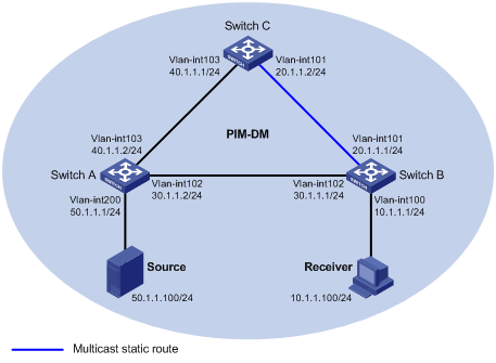
As shown in Figure 5:
· PIM-DM runs in the network. All switches in the network support multicast.
· Switch A, Switch B and Switch C run OSPF.
· Typically, the receiver host can receive the multicast data from the source through the path: Switch A to Switch B, which is the same as the unicast route.
Configure the switches so that the receiver host receives the multicast data from the source through the following path: Switch A to Switch C to Switch B. This path is different than the unicast route.
Configuration procedure
1. Assign an IP address and subnet mask to each interface according to Figure 5. (Details not shown.)
2. Configure OSPF on the switches in the PIM-DM domain. (Details not shown.)
3. Enable IP multicast routing, and enable IGMP and PIM-DM:
# On Switch B, enable IP multicast routing.
<SwitchB> system-view
[SwitchB] multicast routing
[SwitchB-mrib] quit
# Enable IGMP on VLAN-interface 100 (the interface that connects to the receiver host).
[SwitchB] interface vlan-interface 100
[SwitchB-Vlan-interface100] igmp enable
[SwitchB-Vlan-interface100] quit
# Enable PIM-DM on the other interfaces.
[SwitchB] interface vlan-interface 101
[SwitchB-Vlan-interface101] pim dm
[SwitchB-Vlan-interface101] quit
[SwitchB] interface vlan-interface 102
[SwitchB-Vlan-interface102] pim dm
[SwitchB-Vlan-interface102] quit
# On Switch A, enable IP multicast routing, and enable PIM-DM on each interface.
<SwitchA> system-view
[SwitchA] multicast routing
[SwitchA-mrib] quit
[SwitchA] interface vlan-interface 200
[SwitchA-Vlan-interface200] pim dm
[SwitchA-Vlan-interface200] quit
[SwitchA] interface vlan-interface 102
[SwitchA-Vlan-interface102] pim dm
[SwitchA-Vlan-interface102] quit
[SwitchA] interface vlan-interface 103
[SwitchA-Vlan-interface103] pim dm
[SwitchA-Vlan-interface103] quit
# Enable IP multicast routing and PIM-DM on Switch C in the same way Switch A is configured. (Details not shown.)
4. Display the RPF route to Source on Switch B.
[SwitchB] display multicast rpf-info 50.1.1.100
RPF information about source 50.1.1.100:
RPF interface: Vlan-interface102, RPF neighbor: 30.1.1.2
Referenced route/mask: 50.1.1.0/24
Referenced route type: igp
Route selection rule: preference-preferred
Load splitting rule: disable
The output shows that the current RPF route on Switch B is contributed by a unicast routing protocol and the RPF neighbor is Switch A.
5. Configure a static multicast route on Switch B, specifying Switch C as its RPF neighbor on the route to Source.
[SwitchB] ip rpf-route-static 50.1.1.100 24 20.1.1.2
Verifying the configuration
# Display information about the RPF route to Source on Switch B.
[SwitchB] display multicast rpf-info 50.1.1.100
RPF information about source 50.1.1.100:
RPF interface: Vlan-interface101, RPF neighbor: 20.1.1.2
Referenced route/mask: 50.1.1.0/24
Referenced route type: multicast static
Route selection rule: preference-preferred
Load splitting rule: disable
The output shows that:
· The RPF route on Switch B is the configured static multicast route.
· The RPF neighbor of Switch B is Switch C.
Creating an RPF route
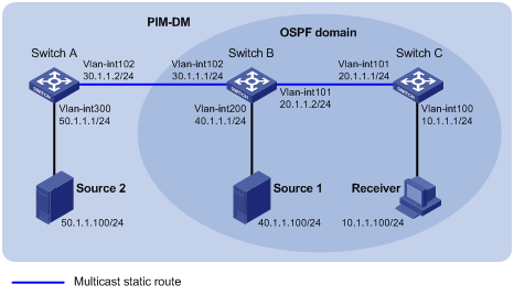
Network requirements
As shown in Figure 6:
· PIM-DM runs in the network and all switches in the network support IP multicast.
· Switch B and Switch C run OSPF, and have no unicast routes to Switch A.
· Typically, the receiver host receives the multicast data from the Source 1 in the OSPF domain.
Configure the switches so that the receiver host receives multicast data from the Source 2, which is outside the OSPF domain.
Configuration procedure
1. Assign an IP address and subnet mask to each interface according to Figure 6. (Details not shown.)
2. Configure OSPF on Switch B and Switch C. (Details not shown.)
3. Enable IP multicast routing, and enable IGMP and PIM-DM:
# On Switch C, enable IP multicast routing.
<SwitchC> system-view
[SwitchC] multicast routing
[SwitchC-mrib] quit
# Enable IGMP on VLAN-interface 100 (the interface that connects to the receiver host).
[SwitchC] interface vlan-interface 100
[SwitchC-Vlan-interface100] igmp enable
[SwitchC-Vlan-interface100] quit
# Enable PIM-DM on VLAN-interface 101.
[SwitchC] interface vlan-interface 101
[SwitchC-Vlan-interface101] pim dm
[SwitchC-Vlan-interface101] quit
# On Switch A, enable IP multicast routing, and enable PIM-DM on each interface.
<SwitchA> system-view
[SwitchA] multicast routing
[SwitchA-mrib] quit
[SwitchA] interface vlan-interface 300
[SwitchA-Vlan-interface300] pim dm
[SwitchA-Vlan-interface300] quit
[SwitchA] interface vlan-interface 102
[SwitchA-Vlan-interface102] pim dm
[SwitchA-Vlan-interface102] quit
# Enable IP multicast routing and PIM-DM on Switch B in the same way Switch A is configured. (Details not shown.)
4. Display information about their RPF routes to Source 2 on Switch B and Switch C.
[SwitchB] display multicast rpf-info 50.1.1.100
[SwitchC] display multicast rpf-info 50.1.1.100
No output is displayed, because no RPF routes to Source 2 exist on Switch B or Switch C.
5. Configure a static multicast route:
# Configure a static multicast route on Switch B, specifying Switch A as its RPF neighbor on the route to Source 2.
[SwitchB] ip rpf-route-static 50.1.1.100 24 30.1.1.2
# Configure a static multicast route on Switch C, specifying Switch B as its RPF neighbor on the route to Source 2.
[SwitchC] ip rpf-route-static 10.1.1.100 24 20.1.1.2
Verifying the configuration
# Display information about their RPF routes to Source 2 on Switch B and Switch C.
[SwitchB] display multicast rpf-info 50.1.1.100
RPF information about source 50.1.1.100:
RPF interface: Vlan-interface102, RPF neighbor: 30.1.1.2
Referenced route/mask: 50.1.1.0/24
Referenced route type: multicast static
Route selection rule: preference-preferred
Load splitting rule: disable
[SwitchC] display multicast rpf-info 50.1.1.100
RPF information about source 50.1.1.100:
RPF interface: Vlan-interface101, RPF neighbor: 20.1.1.2
Referenced route/mask: 50.1.1.0/24
Referenced route type: multicast static
Route selection rule: preference-preferred
Load splitting rule: disable
The output shows that the RPF routes to Source 2 exist on Switch B and Switch C. The routes are the configured static routes.
Multicast forwarding over a GRE tunnel
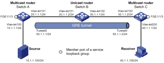
Network requirements
As shown in Figure 7:
· Multicast routing and PIM-DM are enabled on Switch A and Switch C.
· Switch B does not support multicast.
· OSPF is running on Switch A, Switch B, and Switch C.
Configure the switches so that the receiver host can receive the multicast data from the source.
Configuration procedure
1. Assign an IP address and subnet mask to each interface according to Figure 7. (Details not shown.)
2. Configure OSPF on all the switches. (Details not shown.)
3. Configure a GRE tunnel:
# Create service loopback group 1 on Switch A and specify the unicast tunnel service for the group
<SwitchA> system-view
[SwitchA] service-loopback group 1 type tunnel
# Add FortyGigE 1/1/3 of Switch A to service loopback group 1. (FortyGigE 1/1/3 does not belong to VLAN 100 or VLAN 101.)
[SwitchA] interface fortygige 1/1/3
[SwitchA-FortyGigE1/1/3] port service-loopback group 1
[SwitchA-FortyGigE1/1/3] quit
# Create a GRE tunnel interface Tunnel 0 on Switch A, and specify the tunnel mode as GRE/IPv4.
[SwitchA] interface tunnel 0 mode gre
# Assign an IP address to interface Tunnel 0, and specify its source and destination addresses.
[SwitchA-Tunnel0] ip address 50.1.1.1 24
[SwitchA-Tunnel0] source 20.1.1.1
[SwitchA-Tunnel0] destination 30.1.1.2
[SwitchA-Tunnel0] quit
# Create service loopback group 1 on Switch C, and specify the unicast tunnel service for the group.
<SwitchC> system-view
[SwitchC] service-loopback group 1 type tunnel
# Add FortyGigE 1/1/3 of Switch C to service loopback group 1. (FortyGigE 1/1/3 does not belong to VLAN 200 or VLAN 102.)
[SwitchC] interface fortygige 1/1/3
[SwitchC-FortyGigE1/1/3] port service-loopback group 1
[SwitchC-FortyGigE1/1/3] quit
# Create a GRE tunnel interface Tunnel 0 on Switch C, and specify the tunnel mode as GRE/IPv4.
[SwitchC] interface tunnel 0 mode gre
# Assign an IP address to interface Tunnel 0, and specify its source and destination addresses.
[SwitchC-Tunnel0] ip address 50.1.1.2 24
[SwitchC-Tunnel0] source 30.1.1.2
[SwitchC-Tunnel0] destination 20.1.1.1
[SwitchC-Tunnel0] quit
4. Enable IP multicast routing, PIM-DM, and IGMP:
# On Switch A, enable multicast routing, and enable PIM-DM on each interface.
[SwitchA] multicast routing
[SwitchA-mrib] quit
[SwitchA] interface vlan-interface 100
[SwitchA-Vlan-interface100] pim dm
[SwitchA-Vlan-interface100] quit
[SwitchA] interface vlan-interface 101
[SwitchA-Vlan-interface101] pim dm
[SwitchA-Vlan-interface101] quit
[SwitchA] interface tunnel 0
[SwitchA-Tunnel0] pim dm
[SwitchA-Tunnel0] quit
# On Switch C, enable multicast routing.
[SwitchC] multicast routing
[SwitchC-mrib] quit
# Enable IGMP on VLAN-interface 200 (the interface that connects to the receiver host).
[SwitchC] interface vlan-interface 200
[SwitchC-Vlan-interface200] igmp enable
[SwitchC-Vlan-interface200] quit
# Enable PIM-DM on the other interfaces.
[SwitchC] interface vlan-interface 102
[SwitchC-Vlan-interface102] pim dm
[SwitchC-Vlan-interface102] quit
[SwitchC] interface tunnel 0
[SwitchC-Tunnel0] pim dm
[SwitchC-Tunnel0] quit
5. On Switch C, configure a static multicast route, and specify the RPF neighbor toward the source as interface Tunnel 0 on Switch A.
[SwitchC] ip rpf-route-static 50.1.1.0 24 50.1.1.1
Verifying the configuration
# Send an IGMP report from Receiver to join the multicast group 225.1.1.1. (Details not shown.)
# Send multicast data from Source to the multicast group 225.1.1.1. (Details not shown.)
# Display PIM routing table information on Switch C.
[SwitchC] display pim routing-table
Total 1 (*, G) entry; 1 (S, G) entry
(*, 225.1.1.1)
Protocol: pim-dm, Flag: WC
UpTime: 00:04:25
Upstream interface: NULL
Upstream neighbor: NULL
RPF prime neighbor: NULL
Downstream interface(s) information:
Total number of downstreams: 1
1: Vlan-interface200
Protocol: igmp, UpTime: 00:04:25, Expires: -
(10.1.1.100, 225.1.1.1)
Protocol: pim-dm, Flag: ACT
UpTime: 00:06:14
Upstream interface: Tunnel0
Upstream neighbor: 50.1.1.1
RPF prime neighbor: 50.1.1.1
Downstream interface(s) information:
Total number of downstreams: 1
1: Vlan-interface200
Protocol: pim-dm, UpTime: 00:04:25, Expires: -
The output shows that Switch A is the RPF neighbor of Switch C and the multicast data from Switch A is delivered over the GRE tunnel to Switch C.
Troubleshooting multicast routing and forwarding
Static multicast route failure
Symptom
No dynamic routing protocol is enabled on the routers, and the physical status and link layer status of interfaces are both up, but the static multicast route fails.
Solution
To resolve the problem:
1. Use the display multicast routing-table static command to display information about static multicast routes. Verify that the static multicast route has been correctly configured and that the route entry exists in the static multicast routing table.
2. Check the type of the interface that connects the static multicast route to the RPF neighbor. If the interface is not a point-to-point interface, be sure to specify the address for the RPF neighbor.
3. If the problem persists, contact H3C Support.