- Table of Contents
-
- 04-Layer 2 - LAN Switching Configuration Guide
- 00-Preface
- 01-MAC address table configuration
- 02-Ethernet link aggregation configuration
- 03-Port isolation configuration
- 04-Spanning tree configuration
- 05-Loop detection configuration
- 06-VLAN configuration
- 07-MVRP configuration
- 08-QinQ configuration
- 09-VLAN mapping configuration
- 10-LLDP configuration
- Related Documents
-
| Title | Size | Download |
|---|---|---|
| 06-VLAN configuration | 335.54 KB |
Contents
Configuring basic VLAN settings
Configuring basic settings of a VLAN interface
Assigning an access port to a VLAN
Assigning a trunk port to a VLAN
Assigning a hybrid port to a VLAN
Displaying and maintaining VLANs
Port-based VLAN configuration example
Configuring a super VLAN interface
Displaying and maintaining super VLANs
Super VLAN configuration example
Configuration restrictions and guidelines
Displaying and maintaining the private VLAN
Private VLAN configuration examples
Promiscuous port configuration example
Trunk promiscuous port configuration example
Trunk promiscuous and trunk secondary port configuration example
Overview
Ethernet is a family of shared-media LAN technologies based on the CSMA/CD mechanism. An Ethernet LAN is both a collision domain and a broadcast domain. Because the medium is shared, collisions and broadcasts are common in an Ethernet LAN. Typically, bridges and Layer 2 switches can reduce collisions in an Ethernet LAN. To confine broadcasts, a Layer 2 switch must use the Virtual Local Area Network (VLAN) technology.
VLANs enable a Layer 2 switch to break a LAN down into smaller broadcast domains, as shown in Figure 1.
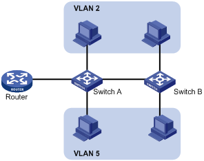
A VLAN is logically divided on an organizational basis rather than on a physical basis. For example, you can assign all workstations and servers used by a particular workgroup to the same VLAN, regardless of their physical locations. Hosts in the same VLAN can directly communicate with one another. You need a router or a Layer 3 switch for hosts in different VLANs to communicate with one another.
All these VLAN features reduce bandwidth waste, improve LAN security, and enable flexible virtual group creation.
VLAN frame encapsulation
To identify Ethernet frames from different VLANs, IEEE 802.1Q inserts a four-byte VLAN tag between the destination and source MAC address (DA&SA) field and the Type field.
Figure 2 VLAN tag placement and format
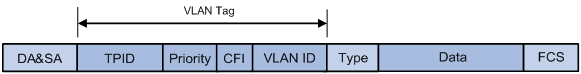
A VLAN tag includes the following fields:
· TPID—16-bit tag protocol identifier that indicates whether a frame is VLAN-tagged. By default, the TPID value is 0x8100 identifies a VLAN-tagged frame. A device vendor can set TPID to a different value. For compatibility with neighbor devices, set the TPID value on the device to be the same as the neighbor device. For information about commands used to modify TPID values, see Layer 2—LAN Switching Command Reference.
· Priority—3-bit long, identifies the 802.1p priority of the frame. For more information, see ACL and QoS Configuration Guide.
· CFI—1-bit long canonical format indicator that indicates whether the MAC addresses are encapsulated in the standard format when packets are transmitted across different media. Available values include:
¡ 0 (default)—The MAC addresses are encapsulated in the standard format.
¡ 1—The MAC addresses are encapsulated in a non-standard format.
This field is always set to 0 for Ethernet.
· VLAN ID—12-bit long, identifies the VLAN that the frame belongs to. The VLAN ID range is 0 to 4095. VLAN IDs 0 and 4095 are reserved, and VLAN IDs 1 to 4094 are user configurable.
The way a network device handles an incoming frame depends on whether the frame has a VLAN-tag and the value of the VLAN tag (if any). For more information, see "Introduction."
Ethernet supports encapsulation formats Ethernet II, 802.3/802.2 LLC, 802.3/802.2 SNAP, and 802.3 raw. The Ethernet II encapsulation format is used here. For how the VLAN tag fields are added to frames encapsulated in the other formats for VLAN identification, see related protocols and standards.
For a frame with multiple VLAN tags, the device handles it according to its outer-most VLAN tag and transmits its inner VLAN tags as the payload.
Protocols and standards
IEEE 802.1Q, IEEE Standard for Local and Metropolitan Area Networks: Virtual Bridged Local Area Networks
Configuring basic VLAN settings
|
Step |
Command |
Remarks |
|
1. Enter system view. |
system-view |
N/A |
|
2. (Optional.) Create a VLAN and enter its view, or create a list of VLANs. |
vlan { vlan-id1 [ to vlan-id2 ] | all } |
By default, only the system default VLAN (VLAN 1) exists. |
|
3. Enter VLAN view. |
vlan vlan-id |
To configure a VLAN after you create a list of VLANs, you must perform this step. |
|
4. Configure a name for the VLAN. |
name text |
By default, the name of a VLAN is VLAN vlan-id. The vlan-id argument specifies the VLAN ID in a four-digit format. If the VLAN ID has fewer than four digits, leading zeros are added. For example, the name of VLAN 100 is VLAN 0100. |
|
5. Configure the description of the VLAN. |
description text |
By default, the description of a VLAN is VLAN vlan-id. The vlan-id argument specifies the VLAN ID in a four-digit format. If the VLAN ID has fewer than four digits, leading zeros are added. For example, the default description of VLAN 100 is VLAN 0100. |
|
|
NOTE: · As the system default VLAN, VLAN 1 cannot be created or deleted. · Before you delete a dynamic VLAN or a VLAN locked by an application, you must first remove the configuration from the VLAN. |
Configuring basic settings of a VLAN interface
For hosts of different VLANs to communicate at Layer 3, you can use VLAN interfaces. VLAN interfaces are virtual interfaces used for Layer 3 communication between different VLANs. They do not exist as physical entities on devices. For each VLAN, you can create one VLAN interface and assign an IP address to it. The VLAN interface acts as the gateway of the VLAN to forward packets destined for another subnet.
When you configure a VLAN interface, follow these restrictions and guidelines:
· Before you create a VLAN interface for a VLAN, create the VLAN first.
· Do not create a VLAN interface for a sub-VLAN. For more information about sub-VLANs, see "Configuring super VLANs."
· Do not create VLAN interfaces for secondary VLANs that have the following characteristics:
¡ Associated with the same primary VLAN.
¡ Enabled with Layer 3 communication in VLAN interface view of the primary VLAN interface.
For more information about secondary VLANs, see "Configuring the private VLAN."
· The MAC address offset configuration and BFD MAD are mutually exclusive on a VLAN interface. For more information about BFD MAD, see Virtual Technologies Configuration Guide.
· To ensure correct traffic forwarding, do not configure MAC address offsets on VLAN interfaces of B-VLANs or FCoE-enabled VLANs. For more information about B-VLANs and FCoE, see SPB Configuration Guide and FCoE Configuration Guide.
· When you configure the private VLAN feature, configure the MAC address offset on the VLAN interface of the primary VLAN. VLAN interfaces of secondary VLANs that are associated with the primary VLAN use the MAC address of the primary VLAN interface. If the primary VLAN interface is not created, the secondary VLAN interfaces use the default MAC address.
The MAC address offset configured on a secondary VLAN interface takes effect only after the secondary VLAN changes into a common VLAN. For more information about the private VLAN feature, see "Configuring the private VLAN."
To configure basic settings of a VLAN interface:
|
Step |
Command |
Remarks |
|
1. Enter system view. |
system-view |
N/A |
|
2. Create a VLAN interface and enter VLAN interface view. |
interface vlan-interface vlan-interface-id |
If the VLAN interface already exists, you enter its view directly. By default, no VLAN interface is created. |
|
3. Assign an IP address to the VLAN interface. |
ip address ip-address { mask | mask-length } [ sub ] |
By default, no IP address is assigned to a VLAN interface. |
|
4. Configure the description of the VLAN interface. |
description text |
The default setting is the VLAN interface name. For example, Vlan-interface1 Interface. |
|
5. Configure the MTU for the VLAN interface. |
mtu size |
The default setting is 1500 bytes. |
|
6. (Optional.) Configure the expected bandwidth of the interface. |
bandwidth bandwidth-value |
By default, the expected bandwidth (in kbps) is the interface baud rate divided by 1000. |
|
7. (Optional.) Restore the default settings for the VLAN interface. |
default |
N/A |
|
8. (Optional.) Cancel the action of manually shutting down the VLAN interface. |
undo shutdown |
By default, a VLAN interface is manually shut down. After you cancel the action of manually shutting down the VLAN interface, the VLAN interface is up if one or more ports in the VLAN is up, and it goes down if all ports in the VLAN go down. |
|
9. (Optional.) Configure the MAC address offset for the VLAN interface. |
mac-address offset value |
By default, all VLAN interfaces on the same device use one MAC address. |
Configuring port-based VLANs
Introduction
Port-based VLANs group VLAN members by port. A port forwards packets from a VLAN only after it is assigned to the VLAN.
Port link type
You can set the link type of a port to access, trunk, or hybrid. The link types use the following VLAN tag handling methods:
· Access—An access port can forward packets from only one VLAN and send these packets untagged. An access port can connect a terminal device that does not support VLAN packets or is used in scenarios that do not distinguish VLANs.
· Trunk—A trunk port can forward packets from multiple VLANs. Except packets from the port VLAN ID (PVID), packets sent out of a trunk port are VLAN-tagged. Ports connecting network devices are typically configured as trunk ports.
· Hybrid—A hybrid port can forward packets from multiple VLANs. The tagging status of the packets forwarded by a hybrid port depends on the port configuration. Hybrid ports are typically used in one-to-two VLAN mapping to remove SVLAN tags for downlink traffic. For more information about one-to-two VLAN mapping, see "Configuring VLAN mapping."
PVID
The PVID identifies the default VLAN of a port.
When you configure the PVID on a port, follow these restrictions and guidelines:
· An access port can join only one VLAN. The VLAN to which the access port belongs is the PVID of the port.
· A trunk or hybrid port supports multiple VLANs and the PVID configuration.
· When you use the undo vlan command to delete the PVID of a port, either of the following events occurs depending on the port link type:
¡ For an access port, the PVID of the port changes to VLAN 1.
¡ For a hybrid or trunk port, the PVID setting on the port does not change.
You can use a nonexistent VLAN as the PVID only for a hybrid or trunk port.
· H3C recommends that you set the same PVID for a local port and its peer.
· To prevent a port from dropping packets from its PVID and untagged packets, assign the port to its PVID.
How ports of different link types handle frames
|
Actions |
Access |
Trunk |
Hybrid |
|
|
In the inbound direction for an untagged frame |
Tags the frame with the PVID tag. |
· If the PVID is permitted on the port, tags the frame with the PVID tag. · If not, drops the frame. |
||
|
In the inbound direction for a tagged frame |
· Receives the frame if its VLAN ID is the same as the PVID. · Drops the frame if its VLAN ID is different from the PVID. |
· Receives the frame if its VLAN is permitted on the port. · Drops the frame if its VLAN is not permitted on the port. |
||
|
In the outbound direction |
Removes the VLAN tag and sends the frame. |
· Removes the tag and sends the frame if the frame carries the PVID tag and the port belongs to the PVID. · Sends the frame without removing the tag if its VLAN is carried on the port but is different from the PVID. |
Sends the frame if its VLAN is permitted on the port. The tagging status of the frame depends on the port hybrid vlan command configuration. |
|
Assigning an access port to a VLAN
You can assign an access port to a VLAN in VLAN view or interface view.
Make sure the VLAN has been created.
Assigning one or multiple access ports to a VLAN in VLAN view
|
Step |
Command |
Remarks |
|
1. Enter system view. |
system-view |
N/A |
|
2. Enter VLAN view. |
vlan vlan-id |
N/A |
|
3. Assign one or multiple access ports to the VLAN. |
port interface-list |
By default, all ports belong to VLAN 1. |
Assigning an access port to a VLAN in interface view
|
Step |
Command |
Remarks |
|
1. Enter system view. |
system-view |
N/A |
|
2. Enter interface view. |
· Enter Layer 2 Ethernet interface view: · Enter Layer 2 aggregate interface view: |
· The configuration made in Layer 2 Ethernet interface view applies only to the port. · The configuration made in Layer 2 aggregate interface view applies to the aggregate interface and its aggregation member ports. If the system fails to apply the configuration to an aggregation member port, it skips the port and moves to the next member port. If the system fails to apply the configuration to the aggregate interface, it stops applying the configuration to aggregation member ports. |
|
3. Set the port link type to access. |
port link-type access |
By default, the link type of a port is access. |
|
4. (Optional.) Assign the access port to a VLAN. |
port access vlan vlan-id |
By default, an access port belongs to VLAN 1. |
Assigning a trunk port to a VLAN
A trunk port supports multiple VLANs. You can assign it to a VLAN in interface view.
When you assign a trunk port to a VLAN, follow these restrictions and guidelines:
· To change the link type of a port from trunk to hybrid or vice versa, set the link type to access first.
· To enable a trunk port to transmit packets from its PVID, you must assign the trunk port to the PVID by using the port trunk permit vlan command.
To assign a trunk port to one or multiple VLANs:
|
Step |
Command |
Remarks |
|
1. Enter system view. |
system-view |
N/A |
|
2. Enter interface view. |
· Enter Layer 2 Ethernet interface view: · Enter Layer 2 aggregate interface view: |
· The configuration made in Layer 2 Ethernet interface view applies only to the port. · The configuration made in Layer 2 aggregate interface view applies to the aggregate interface and its aggregation member ports. If the system fails to apply the configuration to an aggregation member port, it skips the port and moves to the next member port. If the system fails to apply the configuration to the aggregate interface, it stops applying the configuration to aggregation member ports. |
|
3. Set the port link type to trunk. |
port link-type trunk |
By default, all ports are access ports. |
|
4. Assign the trunk port to the specified VLANs. |
port trunk permit vlan { vlan-id-list | all } |
By default, a trunk port permits only VLAN 1. |
|
5. (Optional.) Configure the PVID of the trunk port. |
port trunk pvid vlan vlan-id |
The default setting is VLAN 1. |
Assigning a hybrid port to a VLAN
A hybrid port supports multiple VLANs. You can assign it to the specified VLANs in interface view. Make sure the VLANs have been created.
When you assign a hybrid port to a VLAN, follow these restrictions and guidelines:
· To change the link type of a port from trunk to hybrid or vice versa, set the link type to access first.
· To enable a hybrid port to transmit packets from its PVID, you must assign the hybrid port to the PVID by using the port hybrid vlan command.
To assign a hybrid port to one or multiple VLANs:
|
Step |
Command |
Remarks |
|
1. Enter system view. |
system-view |
N/A |
|
2. Enter interface view. |
· Enter Layer 2 Ethernet interface view: · Enter Layer 2 aggregate interface view: |
· The configuration made in Layer 2 Ethernet interface view applies only to the port. · The configuration made in Layer 2 aggregate interface view applies to the aggregate interface and its aggregation member ports. If the system fails to apply the configuration to an aggregation member port, it skips the port and moves to the next member port. If the system fails to apply the configuration to the aggregate interface, it stops applying the configuration to aggregation member ports. |
|
3. Set the port link type to hybrid. |
port link-type hybrid |
By default, all ports are access ports. |
|
4. Assign the hybrid port to the specified VLANs. |
port hybrid vlan vlan-id-list { tagged | untagged } |
By default, a hybrid port is an untagged member of the VLAN to which the port belongs when its link type is access. |
|
5. (Optional.) Configure the PVID of the hybrid port. |
port hybrid pvid vlan vlan-id |
By default, the PVID of a hybrid port is the ID of the VLAN to which the port belongs when its link type is access. |
Displaying and maintaining VLANs
Execute display commands in any view and reset commands in user view.
|
Task |
Command |
|
Display VLAN interface information. |
display interface vlan-interface [ brief [ down ] ] display interface vlan-interface [ interface-number ] [ brief [ description ] ] |
|
Display VLAN information. |
display vlan [ vlan-id1 [ to vlan-id2 ] | all | dynamic | reserved | static ] |
|
Display brief VLAN information. |
display vlan brief |
|
Display VLAN interface information. |
display interface vlan-interface [ vlan-interface-id ] [ brief [ description ] ] |
|
Display hybrid ports or trunk ports on the device. |
display port { hybrid | trunk } |
|
Clear statistics on a port. |
reset counters interface vlan-interface [ vlan-interface-id ] |
Port-based VLAN configuration example
By default, Ethernet, VLAN, and aggregate interfaces are shut down. You must use the undo shutdown command to bring them up. This example assumes that all these interfaces are already up.
Network requirements
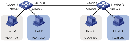
As shown in Figure 3:
· Host A and Host C belong to Department A. VLAN 100 is assigned to Department A.
· Host B and Host D belong to Department B. VLAN 200 is assigned to Department B.
Configure port-based VLANs so that only hosts in the same department can communicate with each other.
Configuration procedure
1. Configure Device A:
# Create VLAN 100, and assign GigabitEthernet 3/0/1 to VLAN 100.
<DeviceA> system-view
[DeviceA] vlan 100
[DeviceA-vlan100] port GigabitEthernet 3/0/1
[DeviceA-vlan100] quit
# Create VLAN 200, and assign GigabitEthernet 3/0/2 to VLAN 200.
[DeviceA] vlan 200
[DeviceA-vlan200] port GigabitEthernet 3/0/2
[DeviceA-vlan200] quit
# Configure GigabitEthernet 3/0/3 as a trunk port, and assign it to VLANs 100 and 200.
[DeviceA] interface GigabitEthernet 3/0/3
[DeviceA-GigabitEthernet3/0/3] port link-type trunk
[DeviceA-GigabitEthernet3/0/3] port trunk permit vlan 100 200
2. Configure Device B in the same way Device A is configured. (Details not shown.)
3. Configure hosts:
¡ Configure Host A and Host C to be on the same IP subnet. For example, 192.168.100.0/24.
¡ Configure Host B and Host D to be on the same IP subnet. For example, 192.168.200.0/24.
Verifying the configuration
# Verify that Host A and Host C can ping each other, but they both fail to ping Host B. (Details not shown.)
# Verify that Host B and Host D can ping each other, but they both fail to ping Host A. (Details not shown.)
# Verify that VLANs 100 and 200 are correctly configured on devices, for example, on Device A.
[DeviceA-GigabitEthernet3/0/3] display vlan 100
VLAN ID: 100
VLAN type: Static
Route interface: Not configured
Description: VLAN 0100
Name: VLAN 0100
Tagged ports:
GigabitEthernet3/0/3
Untagged ports:
GigabitEthernet3/0/1
[DeviceA-GigabitEthernet3/0/3] display vlan 200
VLAN ID: 200
VLAN type: Static
Route interface: Not configured
Description: VLAN 0200
Name: VLAN 0200
Tagged ports:
GigabitEthernet3/0/3
Untagged ports:
GigabitEthernet3/0/2
Hosts in a VLAN typically use IP addresses in the same subnet. For Layer 3 interoperability with other VLANs, you can create a VLAN interface for the VLAN and assign an IP address to it. This requires a large number of IP addresses.
The super VLAN feature was introduced to save IP addresses. A super VLAN is associated with multiple sub-VLANs. These sub-VLANs use the VLAN interface of the super VLAN (also known as the super VLAN interface) as the gateway for Layer 3 communication.
You can create a VLAN interface for a super VLAN and assign an IP address to it. However, you cannot create a VLAN interface for a sub-VLAN. You can assign a physical port to a sub-VLAN, but you cannot assign a physical port to a super VLAN. Sub-VLANs are isolated at Layer 2.
You can enable Layer 3 communication between sub-VLANs by performing the following tasks:
1. Create a super VLAN and the VLAN interface for the super VLAN.
2. Enable local proxy ARP or ND on the super VLAN interface:
¡ In an IPv4 network, enable local proxy ARP on the super VLAN interface. The super VLAN can then process ARP requests and replies sent from the sub-VLANs.
¡ In an IPv6 network, enable local proxy ND on the super VLAN interface. The super VLAN can then process the NS and NA messages sent from the sub-VLANs.
Configuration task list
|
Tasks at a glance |
|
(Required.) Creating a sub-VLAN |
|
(Required.) Configuring a super VLAN |
|
(Required.) Configuring a super VLAN interface |
Creating a sub-VLAN
|
Step |
Command |
Remarks |
|
1. Enter system view. |
system-view |
N/A |
|
2. Create a VLAN that is to be configured as a sub-VLAN. |
vlan vlan-id |
By default, only the system default VLAN (VLAN 1) exists. |
Configuring a super VLAN
When you configure a super VLAN, follow these restrictions and guidelines:
· Do not configure the system default VLAN (VLAN 1) as a super VLAN.
· Do not configure a VLAN as both a super VLAN and a sub-VLAN.
To configure a super VLAN:
|
Step |
Command |
Remarks |
|
1. Enter system view. |
system-view |
N/A |
|
2. Enter VLAN view. |
vlan vlan-id |
If the VLAN does not exist, this command creates the VLAN before accessing its VLAN view. |
|
3. Configure the VLAN as a super VLAN. |
supervlan |
By default, a VLAN is not a super VLAN. |
|
4. Associate the super VLAN with the specified sub-VLANs. |
subvlan vlan-id-list |
By default, a super VLAN is not associated with any sub-VLANs. Make sure the sub-VLANs already exist before associating them with a super VLAN. |
Configuring a super VLAN interface
H3C recommends not configuring VRRP for a super VLAN interface, because the configuration affects network performance. For more information about VRRP, see High Availability Configuration Guide.
To configure a VLAN interface for a super VLAN:
|
Step |
Command |
Remarks |
|
1. Enter system view. |
system-view |
N/A |
|
2. Create a VLAN interface and enter its view. |
interface vlan-interface vlan-interface-id |
The vlan-interface-id argument must be the super VLAN ID. |
|
3. Configure an IP address for the VLAN interface of the super VLAN. |
· Configure an IPv4 address: · Configure an IPv6 address: |
By default, no IP address is configured for a VLAN interface. |
|
4. Configure Layer 3 communication between sub-VLANs. |
· Enable local proxy ARP for devices that run IPv4 protocols: · Enable local proxy ND for devices that run IPv6 protocols: |
By default: · Sub-VLANs cannot communicate with each other at Layer 3. · Local proxy ARP or ND is disabled. For more information about local proxy ARP and proxy ND, see Layer 3—IP Services Configuration Guide. For more information about local-proxy-arp enable and local-proxy-nd enable commands, see Layer 3—IP Services Command Reference. |
Displaying and maintaining super VLANs
Execute display commands in any view.
|
Task |
Command |
|
Display information about super VLANs and their associated sub-VLANs. |
display supervlan [ supervlan-id ] |
Super VLAN configuration example
Network requirements
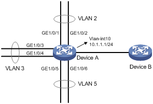
As shown in Figure 4:
· GigabitEthernet 1/0/1 and GigabitEthernet 1/0/2 are in VLAN 2.
· GigabitEthernet 1/0/3 and GigabitEthernet 1/0/4 are in VLAN 3.
· GigabitEthernet 1/0/5 and GigabitEthernet 1/0/6 are in VLAN 5.
· Hosts of VLANs 2, 3, and 5 are on the subnet 10.1.1.0/24.
To save IP addresses and enable VLANs 2, 3, and 5 to be isolated at Layer 2 but interoperable at Layer 3, perform the following tasks:
· Create a super VLAN and assign an IP address to its VLAN interface.
· Associate the super VLAN with VLANs 2, 3, and 5.
Configuration procedure
[DeviceA] vlan 10
[DeviceA-vlan10] quit
# Create VLAN-interface 10, and assign the IP address 10.1.1.1/24 to it.
[DeviceA] interface vlan-interface 10
[DeviceA-Vlan-interface10] ip address 10.1.1.1 255.255.255.0
# Enable local proxy ARP on VLAN-interface 10 .
[DeviceA-Vlan-interface10] local-proxy-arp enable
[DeviceA-Vlan-interface10] quit
# Create VLAN 2, and assign GigabitEthernet 1/0/1 and GigabitEthernet 1/0/2 to the VLAN.
[DeviceA-vlan2] port gigabitethernet 1/0/1 gigabitethernet 1/0/2
[DeviceA-vlan2] quit
# Create VLAN 3, and assign GigabitEthernet 1/0/3 and GigabitEthernet 1/0/4 to the VLAN.
[DeviceA-vlan3] port gigabitethernet 1/0/3 gigabitethernet 1/0/4
[DeviceA-vlan3] quit
# Create VLAN 5, and assign GigabitEthernet 1/0/5 and GigabitEthernet 1/0/6 to the VLAN.
[DeviceA-vlan5] port gigabitethernet 1/0/5 gigabitethernet 1/0/6
[DeviceA-vlan5] quit
# Configure VLAN 10 as a super VLAN, and associate sub-VLANs 2, 3, and 5 with the super VLAN.
[DeviceA-vlan10] supervlan
[DeviceA-vlan10] subvlan 2 3 5
[DeviceA-vlan10] quit
[DeviceA] quit
Verifying the configuration
# Display information about super VLAN 10 and its associated sub-VLANs.
<Sysname> display supervlan
Super VLAN ID: 10
Sub-VLAN ID: 2-3, 5
VLAN ID: 10
VLAN type: Static
It is a super VLAN.
Route interface: Configured
Ipv4 address: 10.1.1.1
Ipv4 subnet mask: 255.255.255.0
Description: VLAN 0010
Name: VLAN 0010
Tagged ports: None
Untagged ports: None
VLAN ID: 2
VLAN type: Static
It is a sub-VLAN.
Route interface: Configured
Ipv4 address: 10.1.1.1
Ipv4 subnet mask: 255.255.255.0
Description: VLAN 0002
Name: VLAN 0002
Tagged ports: None
Untagged ports:
GigabitEthernet1/0/1 GigabitEthernet1/0/2
VLAN ID: 3
VLAN type: Static
It is a sub-VLAN.
Route interface: Configured
Ipv4 address: 10.1.1.1
Ipv4 subnet mask: 255.255.255.0
Description: VLAN 0003
Name: VLAN 0003
Tagged ports: None
Untagged ports:
GigabitEthernet1/0/3 GigabitEthernet1/0/4
VLAN ID: 5
VLAN type: Static
It is a sub-VLAN.
Route interface: Configured
Ipv4 address: 10.1.1.1
Ipv4 subnet mask: 255.255.255.0
Description: VLAN 0005
Name: VLAN 0005
Tagged ports: None
Untagged ports:
GigabitEthernet1/0/5 GigabitEthernet1/0/6
VLAN technology provides a method for isolating traffic from customers. At the access layer of a network, customer traffic must be isolated for security or accounting purposes. If VLANs are assigned on a per user basis, a large number of VLANs will be required.
The private VLAN feature saves VLAN resources. It uses a two-tier VLAN structure as follows:
· Primary VLAN—Used for upstream data exchange. A primary VLAN can be associated with multiple secondary VLANs. The upstream device identifies only the primary VLAN.
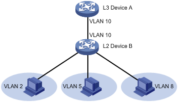
· Secondary VLANs—Used for connecting users. Secondary VLANs are isolated at Layer 2. To implement Layer 3 communication between secondary VLANs associated with the primary VLAN, enable local proxy ARP or ND on the upstream device (for example, L3 Device A in Figure 5).
As shown in Figure 5, the private VLAN feature is enabled on L2 Device B. VLAN 10 is the primary VLAN. VLANs 2, 5, and 8 are secondary VLANs that are associated with VLAN 10. L3 Device A is only aware of VLAN 10.
If the private VLAN feature is configured on a Layer 3 device, use one of the following methods on the Layer 3 device to enable Layer 3 communication. Layer 3 communication might be required between secondary VLANs that are associated with the same primary VLAN, or between secondary VLANs and other networks.
· Method 1:
a. Create VLAN interfaces for the secondary VLANs.
b. Assign IP addresses to the secondary VLAN interfaces.
· Method 2:
a. Enable Layer 3 communication between the secondary VLANs that are associated with the primary VLAN.
b. Create the VLAN interface for the primary VLAN and assign an IP address to it. (Do not create secondary VLAN interfaces if using this method.)
c. Enable local proxy ARP or ND on the primary VLAN interface.
Configuration task list
To configure the private VLAN feature, perform the following tasks:
1. Configure the primary VLAN.
2. Configure the secondary VLANs.
3. Associate the secondary VLANs with the primary VLAN.
4. Configure the uplink and downlink ports:
¡ Configure the uplink port (for example, the port connecting L2 Device B to L3 Device A in Figure 6):
- When the port allows only one primary VLAN, configure the port as a promiscuous port of the primary VLAN. The promiscuous port can be automatically assigned to the primary VLAN and its associated secondary VLANs.
- When the port allows multiple primary VLANs, configure the port as a trunk promiscuous port of the primary VLANs. The trunk promiscuous port can be automatically assigned to the primary VLANs and their associated secondary VLANs.
¡ Configure a downlink port (for example, the port connecting L2 Device B to a host in Figure 5), as a host port. The host port can be automatically assigned to the secondary VLAN and its associated primary VLAN.
¡ If a downlink port allows multiple secondary VLANs, configure the port as a trunk secondary port. The trunk secondary port can be automatically assigned to the secondary VLANs and their associated primary VLANs.
For more information about promiscuous, trunk promiscuous, host, and trunk secondary ports, see Layer 2—LAN Switching Command Reference.
5. Configure Layer 3 communication between the specified secondary VLANs that are associated with the primary VLAN.
Configuration restrictions and guidelines
When you configure the private VLAN feature, follow these restrictions and guidelines:
· To ensure the correct functionality of the private VLAN feature and port isolation, H3C recommends not configuring these two features at the same time. For more information about port isolation, see "Configuring port isolation."
· The private VLAN feature supports only basic protocols, Layer 2 forwarding, and Layer 3 forwarding. A port of a primary or secondary VLAN does not support PVST, BIDIR-PIM, EVI, SPBM, multiport unicast MAC address entries, or multiport ARP entries. The private VLAN interface does not support policy-based routing, multicast VPN, multicasting packets in the primary VLAN and secondary VLANs, or MPLS L3VPN.
· Make sure the following requirements are met:
¡ For a promiscuous port:
- The primary VLAN is the PVID of the port.
- The port is an untagged member of the primary VLAN and secondary VLANs.
¡ For a host port:
- The PVID of the port is a secondary VLAN.
- The port is an untagged member of the primary VLAN and the secondary VLAN.
¡ A trunk promiscuous or trunk secondary port must be a tagged member of the primary VLANs and the secondary VLANs.
· After you configure a primary VLAN, the system automatically synchronizes the dynamic MAC address entries of the primary VLAN with the dynamic MAC address entries of the secondary VLANs.
· VLAN 1 (system default VLAN) does not support the private VLAN configuration.
Configuration procedure
To configure the private VLAN feature:
|
Step |
Command |
Remarks |
|
1. Enter system view. |
system-view |
N/A |
|
2. Create a VLAN and enter VLAN view. |
vlan vlan-id |
N/A |
|
3. Configure the VLAN as a primary VLAN. |
private-vlan primary |
By default, a VLAN is not a primary VLAN. |
|
4. Return to system view. |
quit |
N/A |
|
5. Create one or multiple secondary VLANs. |
vlan { vlan-id1 [ to vlan-id2 ] | all } |
N/A |
|
6. Return to system view. |
quit |
N/A |
|
7. Enter VLAN view of the primary VLAN. |
vlan vlan-id |
N/A |
|
8. Associate the primary VLAN with the secondary VLANs. |
private-vlan secondary vlan-id-list |
By default, a primary VLAN is not associated with any secondary VLANs. |
|
9. Return to system view. |
quit |
N/A |
|
10. Enter interface view of the uplink port. |
interface interface-type interface-number |
N/A |
|
11. Configure the uplink port as a promiscuous or trunk promiscuous port of the specified VLANs. |
· Configure the uplink port as a promiscuous port
of the specified VLAN: · Configure the uplink port as a trunk
promiscuous port of the specified VLANs: |
By default, a port is not a promiscuous or trunk promiscuous port of any VLANs. |
|
12. Return to system view. |
quit |
N/A |
|
13. Enter interface view of the downlink port. |
interface interface-type interface-number |
N/A |
|
14. Assign the downlink port to secondary VLANs. |
a. Set the link type of the port: b. Assign the access port to the specified VLAN: c. Assign the trunk port to the specified VLANs: d. Assign the hybrid port to the specified VLANs: |
Select substep b, c, or d depending on the port link type. |
|
15. Configure the downlink port as a host or trunk secondary port. |
· Configure the downlink port as a host port: · Configure the downlink port as a trunk
secondary port of the specified VLANs: |
By default, a port is not a host or trunk secondary port. |
|
16. Return to system view. |
quit |
N/A |
|
17. Enter VLAN view of a secondary VLAN. |
vlan vlan-id |
N/A |
|
18. (Optional.) Enable Layer 2 communication for ports in the same secondary VLAN. |
undo private-vlan isolated private-vlan community |
By default, ports in the same secondary VLAN can communicate with each other at Layer 2. |
|
19. Return to system view. |
quit |
N/A |
|
20. (Optional.) Configure Layer 3 communication between the specified secondary VLANs. |
a. Enter VLAN interface view of the
primary VLAN interface: b. Enable Layer 3 communication between
secondary VLANs that are associated with the primary VLAN: c. Assign an IPv4 address to the primary VLAN
interface: d. Assign an IPv6 address to the primary VLAN interface: e. Enable local proxy ARP: f. Enable local proxy ND: |
Use substeps a, b, c, and e for devices that run IPv4 protocols. Use substeps a, b, d, and f for devices that run IPv6 protocols. By default: · Secondary VLANs cannot communicate with each other at Layer 3. · No IP address is configured for a VLAN interface. · Local proxy ARP and ND are disabled. For more information about local proxy ARP and ND, see Layer 3—IP Services Configuration Guide. For more information about the local-proxy-arp enable and local-proxy-nd enable commands, see Layer 3—IP Services Command Reference. |
Displaying and maintaining the private VLAN
Execute display commands in any view.
|
Task |
Command |
|
Display information about primary VLANs and their associated secondary VLANs. |
display private-vlan [ primary-vlan-id ] |
Private VLAN configuration examples
By default, Ethernet, VLAN, and aggregate interfaces are shut down. You must use the undo shutdown command to bring them up. These examples assume that all these interfaces are already up.
Promiscuous port configuration example
Network requirements
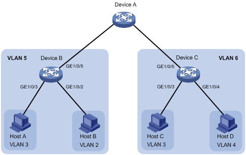
As shown in Figure 6, configure the private VLAN feature to meet the following requirements:
· On Device B, VLAN 5 is a primary VLAN that is associated with secondary VLANs 2 and 3. GigabitEthernet 1/0/5 is in VLAN 5. GigabitEthernet 1/0/2 is in VLAN 2. GigabitEthernet 1/0/3 is in VLAN 3.
· On Device C, VLAN 6 is a primary VLAN that is associated with secondary VLANs 3 and 4. GigabitEthernet 1/0/5 is in VLAN 6. GigabitEthernet 1/0/3 is in VLAN 3. GigabitEthernet 1/0/4 is in VLAN 4.
· Device A is aware of only VLAN 5 on Device B and VLAN 6 on Device C.
Configuration procedure
This example describes the configurations on Device B and Device C.
1. Configure Device B:
# Configure VLAN 5 as a primary VLAN.
<DeviceB> system-view
[DeviceB] vlan 5
[DeviceB-vlan5] private-vlan primary
[DeviceB-vlan5] quit
# Create VLANs 2 and 3.
[DeviceB] vlan 2 to 3
# Associate secondary VLANs 2 and 3 with primary VLAN 5.
[DeviceB] vlan 5
[DeviceB-vlan5] private-vlan secondary 2 to 3
[DeviceB-vlan5] quit
# Configure the uplink port GigabitEthernet 1/0/5 as a promiscuous port of VLAN 5.
[DeviceB] interface gigabitethernet 1/0/5
[DeviceB-GigabitEthernet1/0/5] port private-vlan 5 promiscuous
[DeviceB-GigabitEthernet1/0/5] quit
# Assign the downlink port GigabitEthernet 1/0/2 to VLAN 2, and configure the port as a host port.
[DeviceB] interface gigabitethernet 1/0/2
[DeviceB-GigabitEthernet1/0/2] port access vlan 2
[DeviceB-GigabitEthernet1/0/2] port private-vlan host
[DeviceB-GigabitEthernet1/0/2] quit
# Assign the downlink port GigabitEthernet 1/0/3 to VLAN 3, and configure the port as a host port.
[DeviceB] interface gigabitethernet 1/0/3
[DeviceB-GigabitEthernet1/0/3] port access vlan 3
[DeviceB-GigabitEthernet1/0/3] port private-vlan host
[DeviceB-GigabitEthernet1/0/3] quit
2. Configure Device C:
# Configure VLAN 6 as a primary VLAN.
<DeviceC> system-view
[DeviceC] vlan 6
[DeviceC–vlan6] private-vlan primary
[DeviceC–vlan6] quit
# Create VLANs 3 and 4.
[DeviceC] vlan 3 to 4
# Associate secondary VLANs 3 and 4 with primary VLAN 6.
[DeviceC] vlan 6
[DeviceC-vlan6] private-vlan secondary 3 to 4
[DeviceC-vlan6] quit
# Configure the uplink port GigabitEthernet 1/0/5 as a promiscuous port of VLAN 6.
[DeviceC] interface gigabitethernet 1/0/5
[DeviceC-GigabitEthernet1/0/5] port private-vlan 6 promiscuous
[DeviceC-GigabitEthernet1/0/5] quit
# Assign the downlink port GigabitEthernet 1/0/3 to VLAN 3, and configure the port as a host port.
[DeviceC] interface gigabitethernet 1/0/3
[DeviceC-GigabitEthernet1/0/3] port access vlan 3
[DeviceC-GigabitEthernet1/0/3] port private-vlan host
[DeviceC-GigabitEthernet1/0/3] quit
# Assign the downlink port GigabitEthernet 1/0/4 to VLAN 4, and configure the port as a host port.
[DeviceC] interface gigabitethernet 1/0/4
[DeviceC-GigabitEthernet1/0/4] port access vlan 4
[DeviceC-GigabitEthernet1/0/4] port private-vlan host
[DeviceC-GigabitEthernet1/0/4] quit
Verifying the configuration
# Verify the private VLAN configurations on the devices, for example, on Device B.
[DeviceB] display private-vlan
Primary VLAN ID: 5
Secondary VLAN ID: 2-3
VLAN ID: 5
VLAN type: Static
Private VLAN type: Primary
Route interface: Not configured
Description: VLAN 0005
Name: VLAN 0005
Tagged ports: None
Untagged ports:
GigabitEthernet1/0/2 GigabitEthernet1/0/3
GigabitEthernet1/0/5
VLAN ID: 2
VLAN type: Static
Private VLAN type: Secondary
Route interface: Not configured
Description: VLAN 0002
Name: VLAN 0002
Tagged ports: None
Untagged ports:
GigabitEthernet1/0/2 GigabitEthernet1/0/5
VLAN ID: 3
VLAN type: Static
Private VLAN type: Secondary
Route interface: Not configured
Description: VLAN 0003
Name: VLAN 0003
Tagged Ports: None
Untagged Ports:
GigabitEthernet1/0/3 GigabitEthernet1/0/5
The output shows that:
· The promiscuous port GigabitEthernet 1/0/5 is an untagged member of primary VLAN 5 and secondary VLANs 2 and 3.
· The host port GigabitEthernet 1/0/2 is an untagged member of primary VLAN 5 and secondary VLAN 2.
· The host port GigabitEthernet 1/0/3 is an untagged member of primary VLAN 5 and secondary VLAN 3.
Trunk promiscuous port configuration example
Network requirements
As shown in Figure 7, configure the private VLAN feature to meet the following requirements:
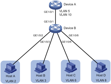
· VLANs 5 and 10 are primary VLANs on Device B. The uplink port GigabitEthernet 1/0/1 on Device B forwards packets from VLANs 5 and 10 with VLAN tags.
· On Device B, the downlink port GigabitEthernet 1/0/2 permits secondary VLAN 2. The downlink port GigabitEthernet 1/0/3 permits secondary VLAN 3. Secondary VLANs 2 and 3 are associated with primary VLAN 5.
· On Device B, the downlink port GigabitEthernet 1/0/6 permits secondary VLAN 6. The downlink port GigabitEthernet 1/0/8 permits secondary VLAN 8. Secondary VLANs 6 and 8 are associated with primary VLAN 10.
· Device A is aware of only VLANs 5 and 10 on Device B.
Configuration procedure
1. Configure Device B:
# Configure VLANs 5 and 10 as primary VLANs.
<DeviceB> system-view
[DeviceB] vlan 5
[DeviceB-vlan5] private-vlan primary
[DeviceB-vlan5] quit
[DeviceB] vlan 10
[DeviceB-vlan10] private-vlan primary
[DeviceB-vlan10] quit
# Create VLANs 2, 3, 6, and 8.
[DeviceB] vlan 2 to 3
[DeviceB] vlan 6
[DeviceB-vlan6] quit
[DeviceB] vlan 8
[DeviceB-vlan8] quit
# Associate secondary VLANs 2 and 3 with primary VLAN 5.
[DeviceB] vlan 5
[DeviceB-vlan5] private-vlan secondary 2 to 3
[DeviceB-vlan5] quit
# Associate secondary VLANs 6 and 8 with primary VLAN 10.
[DeviceB] vlan 10
[DeviceB-vlan10] private-vlan secondary 6 8
[DeviceB-vlan10] quit
# Configure the uplink port GigabitEthernet 1/0/1 as a trunk promiscuous port of VLANs 5 and 10.
[DeviceB] interface gigabitethernet 1/0/1
[DeviceB-GigabitEthernet1/0/1] port private-vlan 5 10 trunk promiscuous
[DeviceB-GigabitEthernet1/0/1] quit
# Assign the downlink port GigabitEthernet 1/0/2 to VLAN 2, and configure the port as a host port.
[DeviceB] interface gigabitethernet 1/0/2
[DeviceB-GigabitEthernet1/0/2] port access vlan 2
[DeviceB-GigabitEthernet1/0/2] port private-vlan host
[DeviceB-GigabitEthernet1/0/2] quit
# Assign the downlink port GigabitEthernet 1/0/3 to VLAN 3, and configure the port as a host port.
[DeviceB] interface gigabitethernet 1/0/3
[DeviceB-GigabitEthernet1/0/3] port access vlan 3
[DeviceB-GigabitEthernet1/0/3] port private-vlan host
[DeviceB-GigabitEthernet1/0/3] quit
# Assign the downlink port GigabitEthernet 1/0/6 to VLAN 6, and configure the port as a host port.
[DeviceB] interface gigabitethernet 1/0/6
[DeviceB-GigabitEthernet1/0/6] port access vlan 6
[DeviceB-GigabitEthernet1/0/6] port private-vlan host
[DeviceB-GigabitEthernet1/0/6] quit
# Assign the downlink port GigabitEthernet 1/0/8 to VLAN 8, and configure the port as a host port.
[DeviceB] interface gigabitethernet 1/0/8
[DeviceB-GigabitEthernet1/0/8] port access vlan 8
[DeviceB-GigabitEthernet1/0/8] port private-vlan host
[DeviceB-GigabitEthernet1/0/8] quit
2. Configure Device A:
# Create VLANs 5 and 10.
[DeviceA] vlan 5
[DeviceA-vlan5] quit
[DeviceA] vlan 10
[DeviceA-vlan10] quit
# Configure GigabitEthernet 1/0/1 as a hybrid port, and assign it to VLANs 5 and 10 as a tagged VLAN member.
[DeviceA] interface gigabitethernet 1/0/1
[DeviceA-GigabitEthernet1/0/1] port link-type hybrid
[DeviceA-GigabitEthernet1/0/1] port hybrid vlan 5 10 tagged
[DeviceA-GigabitEthernet1/0/1] quit
Verifying the configuration
# Verify the primary VLAN configurations on Device B, for example, primary VLAN 5.
[DeviceB] display private-vlan 5
Primary VLAN ID: 5
Secondary VLAN ID: 2-3
VLAN ID: 5
VLAN type: Static
Private VLAN type: Primary
Route interface: Not configured
Description: VLAN 0005
Name: VLAN 0005
Tagged ports:
GigabitEthernet1/0/1
Untagged ports:
GigabitEthernet1/0/2 GigabitEthernet1/0/3
VLAN ID: 2
VLAN type: Static
Private VLAN type: Secondary
Route interface: Not configured
Description: VLAN 0002
Name: VLAN 0002
Tagged ports:
GigabitEthernet1/0/1
Untagged ports:
GigabitEthernet1/0/2
VLAN ID: 3
VLAN type: Static
Private VLAN type: Secondary
Route interface: Not configured
Description: VLAN 0003
Name: VLAN 0003
Tagged ports:
GigabitEthernet1/0/1
Untagged ports:
GigabitEthernet1/0/3
The output shows that:
· The trunk promiscuous port GigabitEthernet 1/0/1 is a tagged member of primary VLAN 5 and secondary VLANs 2 and 3.
· The host port GigabitEthernet 1/0/2 is an untagged member of primary VLAN 5 and secondary VLAN 2.
· The host port GigabitEthernet 1/0/3 is an untagged member of primary VLAN 5 and secondary VLAN 3.
Trunk promiscuous and trunk secondary port configuration example
Network requirements
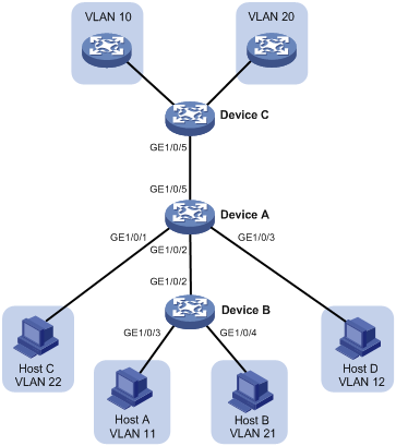
As shown in Figure 8, configure the private VLAN feature to meet the following requirements:
· VLANs 10 and 20 are primary VLANs on Device A. The uplink port GigabitEthernet 1/0/5 on Device A forwards packets from VLANs 10 and 20 with VLAN tags.
· VLANs 11, 12, 21, and 22 are secondary VLANs on Device A.
¡ The downlink port GigabitEthernet 1/0/2 on Device A forwards packets from secondary VLANs 11 and 21 with VLAN tags.
¡ The downlink port GigabitEthernet 1/0/1 on Device A permits secondary VLAN 22.
¡ The downlink port GigabitEthernet 1/0/3 on Device A permits secondary VLAN 12.
· Secondary VLANs 11 and 12 are associated with primary VLAN 10.
· Secondary VLANs 21 and 22 are associated with primary VLAN 20.
Configuration procedure
1. Configure Device A:
# Configure VLANs 10 and 20 as primary VLANs.
<DeviceA> system-view
[DeviceA] vlan 10
[DeviceA-vlan10] private-vlan primary
[DeviceA-vlan10] quit
[DeviceA] vlan 20
[DeviceA-vlan20] private-vlan primary
[DeviceA-vlan20] quit
# Create VLANs 11, 12, 21, and 22.
[DeviceA] vlan 11 to 12
[DeviceA] vlan 21 to 22
# Associate secondary VLANs 11 and 12 with primary VLAN 10.
[DeviceA] vlan 10
[DeviceA-vlan10] private-vlan secondary 11 12
[DeviceA-vlan10] quit
# Associate secondary VLANs 21 and 22 with primary VLAN 20.
[DeviceA] vlan 20
[DeviceA-vlan20] private-vlan secondary 21 22
[DeviceA-vlan20] quit
# Configure the uplink port GigabitEthernet 1/0/5 as a trunk promiscuous port of VLANs 10 and 20.
[DeviceA] interface gigabitethernet 1/0/5
[DeviceA-GigabitEthernet1/0/5] port private-vlan 10 20 trunk promiscuous
[DeviceA-GigabitEthernet1/0/5] quit
# Assign the downlink port GigabitEthernet 1/0/1 to VLAN 22 and configure the port as a host port.
[DeviceA] interface gigabitethernet 1/0/1
[DeviceA-GigabitEthernet1/0/1] port access vlan 22
[DeviceA-GigabitEthernet1/0/1] port private-vlan host
[DeviceA-GigabitEthernet1/0/1] quit
# Assign the downlink port GigabitEthernet 1/0/3 to VLAN 12 and configure the port as a host port.
[DeviceA] interface gigabitethernet 1/0/3
[DeviceA-GigabitEthernet1/0/3] port access vlan 12
[DeviceA-GigabitEthernet1/0/3] port private-vlan host
[DeviceA-GigabitEthernet1/0/3] quit
# Configure the downlink port GigabitEthernet 1/0/2 as a trunk secondary port of VLANs 11 and 21.
[DeviceA] interface gigabitethernet 1/0/2
[DeviceA-GigabitEthernet1/0/2] port private-vlan 11 21 trunk secondary
[DeviceA-GigabitEthernet1/0/2] quit
2. Configure Device B:
# Create VLANs 11 and 21.
<DeviceB> system-view
[DeviceB] vlan 11
[DeviceB-vlan11] quit
[DeviceB] vlan 21
[DeviceB-vlan21] quit
# Configure GigabitEthernet 1/0/2 as a hybrid port, and assign it to VLANs 11 and 21 as a tagged VLAN member.
[DeviceB] interface gigabitethernet 1/0/2
[DeviceB-GigabitEthernet1/0/2] port link-type hybrid
[DeviceB-GigabitEthernet1/0/2] port hybrid vlan 11 21 tagged
[DeviceB-GigabitEthernet1/0/2] quit
# Assign the port GigabitEthernet 1/0/3 to VLAN 11.
[DeviceB] interface gigabitethernet 1/0/3
[DeviceB-GigabitEthernet1/0/3] port access vlan 11
[DeviceB-GigabitEthernet1/0/3] quit
# Assign the port GigabitEthernet 1/0/4 to VLAN 21.
[DeviceB] interface gigabitethernet 1/0/4
[DeviceB-GigabitEthernet1/0/4] port access vlan 21
[DeviceB-GigabitEthernet1/0/4] quit
3. Configure Device C:
# Create VLANs 10 and 20.
<DeviceC> system-view
[DeviceC] vlan 10
[DeviceC-vlan10] quit
[DeviceC] vlan 20
[DeviceC-vlan20] quit
# Configure GigabitEthernet 1/0/5 as a hybrid port, and assign it to VLANs 10 and 20 as a tagged VLAN member.
[DeviceC] interface gigabitethernet 1/0/5
[DeviceC-GigabitEthernet1/0/5] port link-type hybrid
[DeviceC-GigabitEthernet1/0/5] port hybrid vlan 10 20 tagged
[DeviceC-GigabitEthernet1/0/5] quit
Verifying the configuration
# Verify the primary VLAN configurations on Device A, for example, primary VLAN 10.
[DeviceA] display private-vlan 10
Primary VLAN ID: 10
Secondary VLAN ID: 11-12
VLAN ID: 10
VLAN type: Static
Private-vlan type: Primary
Route interface: Not configured
Description: VLAN 0010
Name: VLAN 0010
Tagged ports:
GigabitEthernet1/0/2 GigabitEthernet1/0/5
Untagged ports:
GigabitEthernet1/0/3
VLAN ID: 11
VLAN type: Static
Private-vlan type: Secondary
Route interface: Not configured
Description: VLAN 0011
Name: VLAN 0011
Tagged ports:
GigabitEthernet1/0/2 GigabitEthernet1/0/5
Untagged ports: None
VLAN ID: 12
VLAN type: Static
Private-vlan type: Secondary
Route interface: Not configured
Description: VLAN 0012
Name: VLAN 0012
Tagged ports:
GigabitEthernet1/0/5
Untagged ports:
GigabitEthernet1/0/3
The output shows that:
· The trunk promiscuous port GigabitEthernet 1/0/5 is a tagged member of primary VLAN 10 and secondary VLANs 11 and 12.
· The trunk secondary port GigabitEthernet 1/0/2 is a tagged member of primary VLAN 10 and secondary VLAN 11.
· The host port GigabitEthernet 1/0/3 is an untagged member of primary VLAN 10 and secondary VLAN 12.
Secondary VLAN Layer 3 communication configuration example
Network requirements
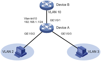
As shown in Figure 9, configure the private VLAN feature to meet the following requirements:
· Primary VLAN 10 on Device A is associated with secondary VLANs 2 and 3. The IP address of VLAN-interface 10 is 192.168.1.1/24.
· The port GigabitEthernet 1/0/1 belongs to VLAN 10. The ports GigabitEthernet 1/0/2 and GigabitEthernet 1/0/3 belong to VLAN 2 and VLAN 3, respectively.
· Secondary VLANs are isolated at Layer 2 but interoperable at Layer 3.
Configuration procedure
# Create VLAN 10 and configure it as a primary VLAN.
[DeviceA] vlan 10
[DeviceA-vlan10] private-vlan primary
[DeviceA-vlan10] quit
# Create VLANs 2 and 3.
<DeviceA> system-view
[DeviceA] vlan 2 to 3
# Associate primary VLAN 10 with secondary VLANs 2 and 3.
[DeviceA] vlan 10
[DeviceA-vlan10] private-vlan primary
[DeviceA-vlan10] private-vlan secondary 2 3
[DeviceA-vlan10] quit
# Configure the uplink port GigabitEthernet 1/0/1 as a promiscuous port of VLAN 10.
[DeviceA] interface gigabitethernet 1/0/1
[DeviceA-GigabitEthernet1/0/1] port private-vlan 10 promiscuous
[DeviceA-GigabitEthernet1/0/1] quit
# Assign the downlink port GigabitEthernet 1/0/2 to VLAN 2, and configure the port as a host port.
[DeviceA] interface gigabitethernet 1/0/2
[DeviceA-GigabitEthernet1/0/2] port access vlan 2
[DeviceA-GigabitEthernet1/0/2] port private-vlan host
[DeviceA-GigabitEthernet1/0/2] quit
# Assign the downlink port GigabitEthernet 1/0/3 to VLAN 3, and configure the port as a host port.
[DeviceA] interface gigabitethernet 1/0/3
[DeviceA-GigabitEthernet1/0/3] port access vlan 3
[DeviceA-GigabitEthernet1/0/3] port private-vlan host
[DeviceA-GigabitEthernet1/0/3] quit
# Enable Layer 3 communication between secondary VLANs 2 and 3 that are associated with primary VLAN 10.
[DeviceA] interface vlan-interface 10
[DeviceA-Vlan-interface10] private-vlan secondary 2 3
# Assign the IP address 192.168.1.1/24 to VLAN-interface 10.
[DeviceA-Vlan-interface10] ip address 192.168.1.1 255.255.255.0
# Enable local proxy ARP on VLAN-interface 10.
[DeviceA-Vlan-interface10] local-proxy-arp enable
[DeviceA-Vlan-interface10] quit
Verifying the configuration
# Display the configuration of primary VLAN 10.
[DeviceA] display private-vlan 10
Primary VLAN ID: 10
Secondary VLAN ID: 2-3
VLAN ID: 10
VLAN type: Static
Private VLAN type: Primary
Route interface: Configured
IPv4 address: 192.168.1.1
IPv4 subnet mask: 255.255.255.0
Description: VLAN 0010
Name: VLAN 0010
Tagged ports: None
Untagged ports:
GigabitEthernet1/0/1 GigabitEthernet1/0/2
GigabitEthernet1/0/3
VLAN ID: 2
VLAN type: Static
Private VLAN type: Secondary
Route interface: Configured
IPv4 address: 192.168.1.1
IPv4 subnet mask: 255.255.255.0
Description: VLAN 0002
Name: VLAN 0002
Tagged ports: None
Untagged ports:
GigabitEthernet1/0/1 GigabitEthernet1/0/2
VLAN ID: 3
VLAN type: Static
Private VLAN type: Secondary
Route interface: Configured
IPv4 address: 192.168.1.1
IPv4 subnet mask: 255.255.255.0
Description: VLAN 0003
Name: VLAN 0003
Tagged ports: None
Untagged ports:
GigabitEthernet1/0/1 GigabitEthernet1/0/3
The Route interface field in the output is Configured, indicating that secondary VLANs 2 and 3 are interoperable at Layer 3.