- Table of Contents
-
- 04-Layer 2 - LAN Switching Configuration Guide
- 00-Preface
- 01-MAC address table configuration
- 02-Ethernet link aggregation configuration
- 03-Port isolation configuration
- 04-Spanning tree configuration
- 05-Loop detection configuration
- 06-VLAN configuration
- 07-MVRP configuration
- 08-QinQ configuration
- 09-VLAN mapping configuration
- 10-LLDP configuration
- Related Documents
-
| Title | Size | Download |
|---|---|---|
| 03-Port isolation configuration | 145.79 KB |
Contents
Configuration restrictions and guidelines
Assigning ports to an isolation group
Displaying and maintaining port isolation
Port isolation configuration examples
Port isolation configuration example
Community VLAN configuration example
|
|
IMPORTANT: · Port isolation is not supported on devices configured with enhanced IRF. For more information about enhanced IRF, see Virtual Technologies Configuration Guide. · In IRF mode, do not configure lite Layer 2 aggregation groups and port isolation groups on the same device. Otherwise, packet forwarding fails. For more information about lite Layer 2 aggregation groups, see Layer 2—LAN Switching Configuration Guide. |
The port isolation feature isolates Layer 2 traffic for data privacy and security without using VLANs.
Ports in an isolation group cannot communicate with each other. However, they can communicate with ports outside the isolation group.
You can configure community VLANs in an isolation group. Ports in an isolation group can communicate with each other if they belong to a VLAN that is specified as a community VLAN.
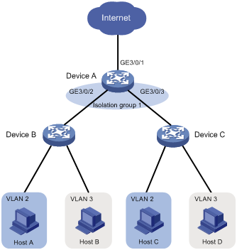
As shown in Figure 1:
· To isolate Host A from Host C, and Host B from Host D, assign ports GigabitEthernet 3/0/2 and GigabitEthernet 3/0/3 on Device A to isolation group 1.
· To enable Layer 2 communication between Host B and Host D (which belong to VLAN 3), specify VLAN 3 as a community VLAN in isolation group 1.
Figure 1 Community VLANs in an isolation group
Configuration restrictions and guidelines
When you configure port isolation, follow these restrictions and guidelines:
· A port in an isolation group only supports MAC address learning, link aggregation, and part of the actions in traffic behaviors applied to incoming traffic of the port. The supported actions include accounting, filter deny, car cir committed-information-rate red discard, and mirror-to.
· HP recommends not configuring Layer 2 protocols (such as GVRP) or Layer 3 protocols (such as multicast and routing protocols) on ports in an isolation group. Otherwise, the ports might function abnormally.
Assigning ports to an isolation group
The device supports multiple isolation groups, which can be configured manually. The number of ports assigned to an isolation group is not limited.
To assign a port to an isolation group:
|
Step |
Command |
Remarks |
|
1. Enter system view. |
system-view |
N/A |
|
2. Create an isolation group. |
port-isolate group group-number |
By default, no isolation group exists. |
|
3. Enter interface view. |
· Enter Layer 2 Ethernet interface view: · Enter Layer 2 aggregate interface view: |
· The configuration in Layer 2 Ethernet interface view applies only to the interface. · The configuration in Layer 2 aggregate interface view applies to the Layer 2 aggregate interface and its aggregation member ports. If the device fails to apply the configuration to the aggregate interface, it does not assign any aggregation member port to the isolation group. If the failure occurs on an aggregation member port, the device skips the port and continues to assign other aggregation member ports to the isolation group. |
|
4. Assign the port to an isolation group. |
port-isolate enable group group-number |
By default, the port is not in any isolation group. You can assign a port to only one isolation group. If you execute the port-isolate enable group command multiple times, the most recent configuration takes effect. |
Configuring community VLANs
|
|
IMPORTANT: This feature is available when the switch is operating in standalone mode or IRF mode with enhanced IRF disabled. |
You can specify VLANs as community VLANs in an isolation group. Ports within the same community VLAN can communicate with each other.
To configure community VLANs for an isolation group:
|
Step |
Command |
Remarks |
|
1. Enter system view. |
system-view |
N/A |
|
2. Create an isolation group and enter the isolation group view. |
port-isolate group group-number |
If the isolation group already exists, you enter its view directly. |
|
3. Specify the community VLANs. |
community-vlan vlan { vlan-id-list | all } |
By default, an isolation group does not contain any community VLANs. |
Displaying and maintaining port isolation
Execute the display command in any view.
|
Task |
Command |
|
Display isolation group information. |
display port-isolate group [ group-number ] |
Port isolation configuration examples
Port isolation configuration example
By default, Ethernet, VLAN, and aggregate interfaces are shut down. You must use the undo shutdown command to bring them up. The examples assume that all these interfaces are already up.
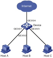
Network requirements
As shown in Figure 2, configure port isolation on the device to provide Internet access for the hosts and isolate them from one another at Layer 2.
Configuration procedure
# Create isolation group 2.
<Device> system-view
[Device] port-isolate group 2
[Device-port-isolate-group2] quit
# Assign GigabitEthernet 3/0/1, GigabitEthernet 3/0/2, and GigabitEthernet 3/0/3 to isolation group 2.
[Device] interface GigabitEthernet 3/0/1
[Device-GigabitEthernet3/0/1] port-isolate enable group 2
[Device-GigabitEthernet3/0/1] quit
[Device] interface GigabitEthernet 3/0/2
[Device-GigabitEthernet3/0/2] port-isolate enable group 2
[Device-GigabitEthernet3/0/2] quit
[Device] interface GigabitEthernet 3/0/3
[Device-GigabitEthernet3/0/3] port-isolate enable group 2
[Device-GigabitEthernet3/0/3] quit
Verifying the configuration
# Display information about isolation group 2.
[Device] display port-isolate group 2
Port isolation group information:
Group ID: 2
Group members:
GigabitEthernet3/0/1 GigabitEthernet3/0/2 GigabitEthernet3/0/3
Community VLAN ID: None
The output shows that ports GigabitEthernet 3/0/1, GigabitEthernet 3/0/2, and GigabitEthernet 3/0/3 are assigned to isolation group 2. As a result, Host A, Host B, and Host C are isolated from one another at layer 2.
Community VLAN configuration example
By default, Ethernet, VLAN, and aggregate interfaces are shut down. You must use the undo shutdown command to bring them up. The examples assume that all these interfaces are already up.
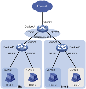
Network requirements
As shown in Figure 3, the company branches Site 1 and Site 2 transfer service traffic in VLAN 2 and VLAN 3.
Configure port isolation and community VLANs on the network to meet the following requirements:
· All hosts can access the Internet through Device A.
· Host B and Host D can exchange video conferencing traffic in VLAN 3.
· Other Layer 2 traffic between Device B and Device C is isolated.
Configuration procedure
1. Configure Device A:
# Create VLAN 2 and VLAN 3.
<DeviceA> system-view
[DeviceA] vlan 2 to 3
# Configure port GigabitEthernet 3/0/2 as a trunk port, and assign it to VLAN 2 and VLAN 3.
[DeviceA] interface GigabitEthernet 3/0/2
[DeviceA-GigabitEthernet3/0/2] port link-type trunk
[DeviceA-GigabitEthernet3/0/2] port trunk permit vlan 2 3
[DeviceA-GigabitEthernet3/0/2] quit
# Configure port GigabitEthernet 3/0/3 as a trunk port, and assign it to VLAN 2 and VLAN 3.
[DeviceA] interface GigabitEthernet 3/0/3
[DeviceA-GigabitEthernet3/0/3] port link-type trunk
[DeviceA-GigabitEthernet3/0/3] port trunk permit vlan 2 3
[DeviceA-GigabitEthernet3/0/3] quit
# Create isolation group 1.
[DeviceA] port-isolate group 1
[DeviceA-port-isolate-group1] quit
# Assign ports GigabitEthernet 3/0/2 and GigabitEthernet 3/0/3 to isolation group 1.
[DeviceA] interface GigabitEthernet 3/0/2
[DeviceA-GigabitEthernet3/0/2] port-isolate enable group 1
[DeviceA-GigabitEthernet3/0/2] quit
[DeviceA] interface GigabitEthernet 3/0/3
[DeviceA-GigabitEthernet3/0/3] port-isolate enable group 1
[DeviceA-GigabitEthernet3/0/3] quit
# Configure VLAN 3 as a community VLAN in isolation group 1.
[DeviceA] port-isolate group 1
[DeviceA-port-isolate-group1] community-vlan vlan 3
[DeviceA-port-isolate-group1] quit
2. Configure Device B:
# Create VLAN 2 and assign ports GigabitEthernet 3/0/2 to it.
[DeviceB] vlan 2
[DeviceB-vlan2] port GigabitEthernet 3/0/2
[DeviceB-vlan2] quit
# Create VLAN 3 and assign ports GigabitEthernet 3/0/3 to it.
[DeviceB] vlan 3
[DeviceB-vlan3] port GigabitEthernet 3/0/3
[DeviceB-vlan3] quit
# Configure GigabitEthernet 3/0/1 as a trunk port, and assign it to VLAN 2 and VLAN 3.
[DeviceB] interface GigabitEthernet 3/0/1
[DeviceB-GigabitEthernet3/0/1] port link-type trunk
[DeviceB-GigabitEthernet3/0/1] port trunk permit vlan 2 3
3. Configure Device C in the same way Device B is configured.
Verifying the configuration
# Display information about isolation group 1 on device A.
[DeviceA] display port-isolate group 1
Port-isolate group information:
Group ID: 1
Group members:
GigabitEthernet3/0/2 GigabitEthernet3/0/3
Community VLAN ID: 3
The output shows that:
· GigabitEthernet3/0/2 and GigabitEthernet3/0/3 are assigned to isolation group 1.
· VLAN 3 is configured as a community VLAN in the isolation group.