- Table of Contents
-
- 08-IP Multicast Configuration Guide
- 00-Preface
- 01-Multicast Overview
- 02-IGMP Snooping Configuration
- 03-PIM Snooping Configuration
- 04-Multicast VLAN Configuration
- 05-Multicast Routing and Forwarding Configuration
- 06-IGMP Configuration
- 07-PIM Configuration
- 08-MSDP Configuration
- 09-MBGP Configuration
- 10-Multicast VPN Configuration
- 11-MLD Snooping Configuration
- 12-IPv6 PIM Snooping Configuration
- 13-IPv6 Multicast VLAN Configuration
- 14-IPv6 Multicast Routing and Forwarding Configuration
- 15-MLD Configuration
- 16-IPv6 PIM Configuration
- 17-IPv6 MBGP Configuration
- Related Documents
-
| Title | Size | Download |
|---|---|---|
| 15-MLD Configuration | 360.5 KB |
Contents
Configuring basic MLD functions
Configuring an IPv6 multicast group filter
Setting the maximum number of IPv6 multicast groups that an interface can join
Configuring Router-Alert option handling methods
Configuring MLD queries and response parameters
Configuring MLD fast-leave processing
Enabling the MLD host tracking function
Configuring IPv6 multicast forwarding on a downstream interface
Displaying and maintaining MLD
Basic MLD functions configuration example
MLD SSM mapping configuration example
MLD proxying configuration example
No member information exists on the receiver-side router
Inconsistent memberships on routers on the same subnet
Overview
The Multicast Listener Discovery protocol (MLD) is used by an IPv6 router to discover the presence of multicast listeners on the directly attached subnets. Multicast listeners are nodes wishing to receive IPv6 multicast packets.
Through MLD, the router can learn whether any IPv6 multicast listeners exist on the directly connected subnets, put corresponding records in the database, and maintain timers related to IPv6 multicast addresses.
Routers running MLD use an IPv6 unicast link-local address as the source address to send MLD messages. MLD messages are Internet Control Message Protocol for IPv6 (ICMPv6) messages. All MLD messages are confined to the local subnet, with a hop count of 1.
The term "router" in this document refers to both routers and Layer 3 switches.
MLD versions
· MLDv1 (defined in RFC 2710), which is derived from IGMPv2.
· MLDv2 (defined in RFC 3810), which is derived from IGMPv3.
All MLD versions support the ASM model. In addition, MLDv2 can directly implement the SSM model, but MLDv1 must work with the MLD SSM mapping function to implement SSM service. For more information about the ASM and SSM models, see "Multicast overview."
How MLDv1 operates
MLDv1 implements IPv6 multicast listener management based on the query/response mechanism.
MLD querier election
All IPv6 multicast routers on the same subnet can monitor MLD listener report messages (often called "reports") from hosts, but the subnet needs only one router to act as the MLD querier to send MLD query messages (often called "queries"). A querier election mechanism determines which router will act as the MLD querier on the subnet.
1. Initially, every MLD router assumes itself as the querier and sends MLD general query messages (often called "general queries") to all hosts and routers on the local subnet with destination address of FF02::1.
2. After receiving a general query, every MLD router compares the source IPv6 address of the query message with its own interface address. After comparison, the router with the lowest IPv6 address wins the querier election and becomes the querier, and all other routers become non-queriers.
3. All the non-queriers start a timer, called the "other querier present timer." If a router receives an MLD query from the querier before the timer expires, it resets this timer. Otherwise, it assumes that the querier has timed out and initiates a new querier election process.
Joining an IPv6 multicast group
Figure 1 MLD queries and reports
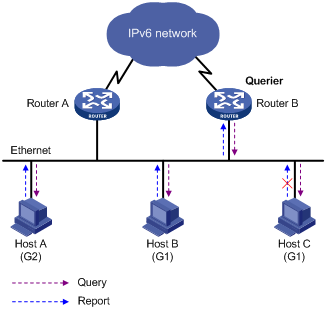
As shown in Figure 1, assume that Host B and Host C receive IPv6 multicast data addressed to IPv6 multicast group G1, and Host A receive IPv6 multicast data addressed to G2. The following process describes how the hosts join the IPv6 multicast groups and how the MLD querier (Router B in the figure) maintains the IPv6 multicast group memberships:
1. The hosts send unsolicited MLD reports to the addresses of the IPv6 multicast groups that they want to join, without having to wait for the MLD queries from the MLD querier.
2. The MLD querier periodically multicasts MLD queries (with the destination address of FF02::1) to all hosts and routers on the local subnet.
3. After receiving a query message, Host B or Host C (the delay timer of whichever expires first) sends an MLD report to the IPv6 multicast group address of G1, to announce its membership for G1. Assume that Host B sends the report message. After hearing the report from Host B, Host C, which is on the same subnet as Host B, suppresses its own report for G1, because the MLD routers (Router A and Router B) have already known that at least one host on the local subnet is interested in G1. This mechanism, known as the "MLD report suppression", helps reduce traffic on the local subnet.
4. At the same time, because Host A is interested in G2, it sends a report to the IPv6 multicast group address of G2.
5. Through the query/report process, the MLD routers learn that members of G1 and G2 are attached to the local subnet, and the IPv6 multicast routing protocol (IPv6 PIM for example) that is running on the routers generates (*, G1) and (*, G2) multicast forwarding entries. These entries will be the basis for subsequent IPv6 multicast forwarding, where the asterisk (*) represents any IPv6 multicast source.
6. When the IPv6 multicast data addressed to G1 or G2 reaches an MLD router, because the (*, G1) and (*, G2) multicast forwarding entries exist on the MLD router, the router forwards the IPv6 multicast data to the local subnet, and then the receivers on the subnet receive the data.
Leaving an IPv6 multicast group
When a host leaves a multicast group, the following process occurs:
1. The host sends an MLD done message to all IPv6 multicast routers on the local subnet with the destination address of FF02::2.
2. After receiving the MLD done message, the querier sends a configurable number of multicast-address-specific queries to the group that the host is leaving. The destination address field and group address field of the message are both filled with the address of the IPv6 multicast group that is being queried.
3. One of the remaining members, if any on the subnet, of the group being queried should send a report within the time of the maximum response delay set in the query messages.
4. If the querier receives a report for the group before the maximum response timer expires, it maintains the memberships for the IPv6 multicast group. Otherwise, the querier assumes that the multicast group has not member hosts on the local subnet and stops maintaining the memberships for the group.
How MLDv2 operates
Compared with MLDv1, MLDv2 provides the following new features:
IPv6 multicast group filtering
MLDv2 has introduced IPv6 multicast source filtering modes (Include and Exclude), so that a host not only can join a designated IPv6 multicast group, but also can specify to receive or reject multicast data from designated IPv6 multicast sources. When a host joins an IPv6 multicast group, one of the following situation occurs:
· If it expects IPv6 multicast data from specific IPv6 multicast sources like S1, S2, …, it sends a report with Filter-Mode denoted as "Include Sources (S1, S2, …)."
· If it does not expect IPv6 multicast data from specific IPv6 multicast sources like S1, S2, …, it sends a report with Filter-Mode denoted as "Exclude Sources (S1, S2, …)."
As shown in Figure 2, the network comprises two IPv6 multicast sources, Source 1 (S1) and Source 2 (S2), both of which can send IPv6 multicast data to IPv6 multicast group G. Host B is interested only in the IPv6 multicast data that Source 1 sends to G but not in the data from Source 2.
Figure 2 Flow paths of multicast-address-and-source-specific multicast traffic
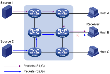
In the case of MLDv1, Host B cannot select IPv6 multicast sources when it joins IPv6 multicast group G. Therefore, IPv6 multicast streams from both Source 1 and Source 2 will flow to Host B whether it needs them or not.
When MLDv2 is running on the hosts and routers, Host B can explicitly express its interest in the IPv6 multicast data that Source 1 sends to G (denoted as (S1, G)), rather than the IPv6 multicast data that Source 2 sends to G (denoted as (S2, G)). Thus, only IPv6 multicast data from Source 1 will be delivered to Host B.
MLD state
A multicast router that is running MLDv2 maintains the multicast address state per multicast address per attached subnet. The multicast address state consists of the following information:
· Filter mode—The router keeps tracing the Include or Exclude state.
· List of sources—The router keeps tracing the newly added or deleted IPv6 multicast source.
· Timers—Filter timers which include the time that the router waits before switching to the Include mode after an IPv6 multicast address times out and source timers for source recording.
Receiver host state listening
MLD message types
The following descriptions are based on MLDv2 messages.
MLD query message
An MLD querier identifies the multicast listening state of neighbor interfaces by sending MLD query messages. The dark area in Figure 3 shows the format of an MLDv1 message.
Figure 3 Format of MLDv2 query message
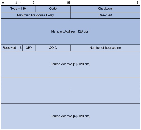
Table 1 Description on fields in an MLDv2 query message
|
Field |
Description |
|
Type = 130 |
Message type. For a query message, this field is set to 130. |
|
Code |
Initialized to zero. |
|
Checksum |
Standard IPv6 checksum. |
|
Maximum Response Delay |
Maximum response delay allowed before a host sends a report message. |
|
Reserved |
Reserved field and initialized to zero. |
|
Multicast Address |
· This field is set to 0 in a general query message. · It is set to a specific IPv6 multicast address in a multicast-address-specific query message or multicast-address-and-source-specific query message. |
|
S |
Flag indicating whether a router updates the timer for suppression after receiving a query message. |
|
QRV |
Querier's Robustness Variable. |
|
QQIC |
Querier's Query Interval Code. |
|
Number of Sources |
· This field is set to 0 in a general query message or a multicast-address-specific query message. · This field represents the number of source addresses in a multicast-address-and-source-specific query message. |
|
Source Address( i ) |
IPv6 multicast source address in a multicast-address-specific query message. (i = 1, 2, .., n, where n represents the number of multicast source addresses.) |
MLD report message
A host sends an MLD report message to report the current multicast listening state. Figure 4 shows the format of an MLD report message.
Figure 4 Format of MLDv2 report message
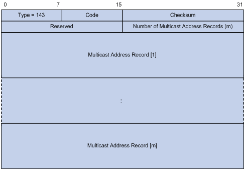
Table 2 Description on fields in an MLDv2 report message
|
Field |
Description |
|
Type = 143 |
Message type. For a report message, this field is set to 143. |
|
Reserved |
The Reserved fields are set to 0 on transmission and ignored on reception. |
|
Checksum |
Standard IPv6 checksum. |
|
Number of Multicast Address Records |
This field indicates how many IPv6 multicast address records are present in this report message. |
|
Multicast Address Record(i) |
This field represents information of each IPv6 multicast address the host listens to on the interface from which the report message is sent, including record type, IPv6 multicast address, and IPv6 multicast source address on the sender. (i= 1, 2, ... m, where m represents the number of IPv6 multicast address records.) |
MLD SSM mapping
The MLD SSM mapping feature enables you to configure static MLD SSM mappings on the last hop router to provide SSM support for receiver hosts that are running MLDv1. The SSM model assumes that the last hop router has identified the desired IPv6 multicast sources when receivers join IPv6 multicast groups.
· When a host that is running MLDv2 joins a multicast group, it can explicitly specify one or more multicast sources in its MLDv2 report.
· A host that is running MLDv1, however, cannot specify multicast source addresses in its MLDv1 report. In this case, you must configure the MLD SSM mapping feature to translate the (*, G) information in the MLDv1 report into (G, INCLUDE, (S1, S2...)) information.
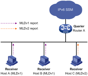
As shown in Figure 5, on an IPv6 SSM network, Host A and Host B are running MLDv1 and Host C is running MLDv2. To provide SSM service for all the hosts if MLDv2 is not available on Host A and Host B, you need to configure the MLD SSM mapping feature on Router A.
With the MLD SSM mapping feature configured, when Router A receives an MLDv1 report, it checks the IPv6 multicast group address G carried in the message:
· If G is not in the IPv6 SSM group range, Router A cannot provide the SSM service but can provide the ASM service.
· If G is in the IPv6 SSM group range but no MLD SSM mappings that correspond to the IPv6 multicast group G have been configured on Router A, Router A cannot provide SSM service and drops the packet.
· If G is in the IPv6 SSM group range, and the MLD SSM mappings have been configured on Router A for multicast group G, Router A translates the (*, G) information in the MLD report into (G, INCLUDE, (S1, S2...)) information based on the configured MLD SSM mappings and provides SSM service accordingly.
For more information about the IPv6 SSM group range, see "Configuring IPv6 PIM."
|
|
NOTE: The MLD SSM mapping feature does not process MLDv2 reports. |
MLD proxying
In some simple tree-shaped topologies, you do not need to configure complex IPv6 multicast routing protocols, such as IPv6 PIM, on the boundary devices. Instead, you can configure MLD proxying on these devices. With MLD proxying configured, the device serves as a proxy for the downstream hosts to send MLD messages, maintain group memberships, and implement IPv6 multicast forwarding based on the memberships. In this case, the MLD proxy device is a host but no longer an IPv6 PIM neighbor to the upstream device.
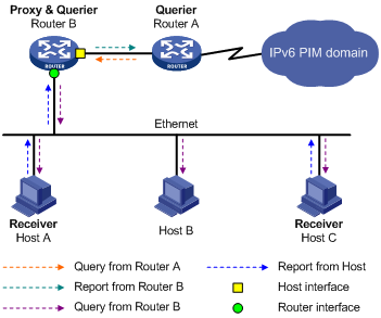
As shown in Figure 6, two types of interfaces are defined on a MLD proxy device:
· Upstream interface—Also called the "proxy interface." A proxy interface is an interface on which MLD proxying is configured. It is in the direction toward the root of the multicast forwarding tree. An upstream interface acts as a host that is running MLD. Therefore, it is also called a "host interface."
· Downstream interface—An interface that is running MLD and not in the direction toward the root of the multicast forwarding tree. A downstream interface acts as a router that is running MLD. Therefore, it is also called a "router interface."
A device with MLD proxying configured maintains a group membership database, which stores the group memberships on all the downstream interfaces in this database. Each entry comprises the multicast address, filter mode, and source list. Such an entry is a collection of members in the same multicast group on each downstream interface.
A proxy device performs host functions on the upstream interface based on the database. It responds to the queries according to the information in the database or sends join/leave messages when the database changes. The proxy device performs router functions on the downstream interfaces by participating in the querier election, sending queries, and maintaining memberships based on the reports.
Protocols and standards
· RFC 2710, Multicast Listener Discovery (MLD) for IPv6
· RFC 3810, Multicast Listener Discovery Version 2 (MLDv2) for IPv6
· RFC 4605, Internet Group Management Protocol (IGMP)/Multicast Listener Discovery (MLD)-Based Multicast Forwarding ("IGMP/MLD Proxying")
MLD configuration task list
|
Task |
Remarks |
|
|
Required. |
||
|
Optional. |
||
|
Optional. |
||
|
Optional. |
||
|
Setting the maximum number of IPv6 multicast groups that an interface can join |
Optional. |
|
|
Optional. |
||
|
Optional. |
||
|
Optional. |
||
|
Optional. |
||
|
Optional. |
||
|
Optional. |
||
|
Optional. |
||
|
Configuring IPv6 multicast forwarding on a downstream interface |
Optional. |
|
For the configuration tasks described in this section:
· In MLD view, the configuration takes effect globally. In interface view, the configuration takes effect on only the current interface.
· If no configuration is performed in interface view, the global configuration in MLD view will apply to that interface. Configurations performed in interface view take precedence over those performed in MLD view.
Configuring basic MLD functions
Before you configure basic MLD functions, complete the following tasks:
· Enable IPv6 forwarding and configure an IPv6 unicast routing protocol so that all devices in the domain can be interoperable at the network layer.
· Configure IPv6 PIM-DM or IPv6 PIM-SM.
· Determine the MLD version.
· Determine the IPv6 multicast group address and IPv6 multicast source address for static group member configuration.
· Determine the ACL rule for IPv6 multicast group filtering.
· Determine the maximum number of IPv6 multicast groups that an interface can join.
Enabling MLD
Enable MLD on the interface on which IPv6 multicast group memberships will be created and maintained.
To enable MLD:
|
Step |
Command |
Remarks |
|
1. Enter system view. |
system-view |
N/A |
|
2. Enable IPv6 multicast routing. |
multicast ipv6 routing-enable |
Disable by default. |
|
3. Enter interface view. |
interface interface-type interface-number |
N/A |
|
4. Enable MLD. |
mld enable |
Disabled by default. |
Configuring the MLD version
Because MLD message types and formats vary with MLD versions, the same MLD version should be configured for all routers on the same subnet before MLD can operate correctly.
Configuring an MLD version globally
|
Step |
Command |
Remarks |
|
1. Enter system view. |
system-view |
N/A |
|
2. Enter MLD view. |
mld |
N/A |
|
3. Configure an MLD version globally. |
version version-number |
MLDv1 by default. |
Configuring an MLD version on an interface
|
Step |
Command |
Remarks |
|
1. Enter system view. |
system-view |
N/A |
|
2. Enter interface view. |
interface interface-type interface-number |
N/A |
|
3. Configure an MLD version on the interface. |
mld version version-number |
MLDv1 by default. |
Configuring static joining
After an interface is configured as a static member of an IPv6 multicast group or an IPv6 multicast source and group, it will act as a virtual member of the IPv6 multicast group to receive IPv6 multicast data addressed to that IPv6 multicast group for the purpose of testing IPv6 multicast data forwarding.
Configuration guidelines
· Before you can configure an interface of an IPv6 PIM-SM device as a static member of an IPv6 multicast group or an IPv6 multicast source and group, if the interface is MLD and IPv6 PIM-SM enabled, it must be an IPv6 PIM-SM DR. If this interface is MLD enabled but not IPv6 PIM-SM enabled, it must be an MLD querier. For more information about IPv6 PIM-SM and a DR, see "Configuring IPv6 PIM."
· A static member port does not respond to queries from the MLD querier. When you configure an interface as a static member port or remove this configuration on the interface, the interface does not unsolicitedly send any MLD report or an MLD done message. In other words, the interface is not a real member of the IPv6 multicast group or the IPv6 multicast and source group.
Configuration procedure
To configure a static member of an IPv6 multicast group or an IPv6 multicast source and group:
|
Step |
Command |
Remarks |
|
1. Enter system view. |
system-view |
N/A |
|
2. Enter interface view. |
interface interface-type interface-number |
N/A |
|
3. Configure a static member of an IPv6 multicast group or an IPv6 multicast source and group. |
mld static-group ipv6-group-address [ source ipv6-source-address ] |
By default, an interface is not a static member of any IPv6 multicast group or IPv6 multicast source and group. |
Configuring an IPv6 multicast group filter
To restrict the hosts on the network attached to an interface from joining certain IPv6 multicast groups, you can set an IPv6 ACL rule on the interface so that the interface maintains only the IPv6 multicast groups matching the ACL.
To configure an IPv6 multicast group filter:
|
Step |
Command |
Remarks |
|
1. Enter system view. |
system-view |
N/A |
|
2. Enter interface view. |
interface interface-type interface-number |
N/A |
|
3. Configure an IPv6 multicast group filter. |
mld group-policy acl6-number [ version-number ] |
By default, no IPv6 group filter is configured on the interface. Hosts on the current interface can join any valid multicast group. |
Setting the maximum number of IPv6 multicast groups that an interface can join
|
Step |
Command |
Remarks |
|
1. Enter system view. |
system-view |
N/A |
|
2. Enter interface view. |
interface interface-type interface-number |
N/A |
|
3. Configure the maximum number of IPv6 multicast groups that the interface can join. |
mld group-limit limit |
The default upper limit depends on the system operating mode. For more information, see Fundamentals Configuration Guide. |
|
|
NOTE: This configuration takes effect on dynamically joined IPv6 multicast groups but not on the statically configured multicast groups. |
Adjusting MLD performance
Before adjusting MLD performance, complete the following tasks:
· Enable IPv6 forwarding and configure an IPv6 unicast routing protocol so that all devices in the domain can be interoperable at the network layer.
· Configure basic MLD functions.
· Determine the startup query interval.
· Determine the startup query count.
· Determine the MLD query interval.
· Determine the MLD querier's robustness variable.
· Determine the maximum response delay of MLD general query messages.
· Determine the MLD last listener query interval.
· Determine the MLD other querier present interval.
Configuring Router-Alert option handling methods
MLD queries include multicast-address-specific queries and multicast-address-and-source-specific queries, and IPv6 multicast groups change dynamically, so a device cannot maintain the information for all IPv6 multicast sources and groups. Therefore, a router might receive IPv6 multicast packets addressed to IPv6 multicast groups that have no members on the local subnet. In this case, the Router-Alert option carried in the IPv6 multicast packets is useful for the router to determine whether to deliver the IPv6 multicast packets to the upper-layer protocol for processing. For more information about the Router-Alert option, see RFC 2113.
An MLD message is processed differently depending on whether it carries the Router-Alert option in the IPv6 header, as follows:
· By default, in consideration of compatibility, the device does not check the Router-Alert option. It processes all received MLD messages. In this case, the device passes MLD messages to the upper layer protocol for processing, whether the MLD messages carry the Router-Alert option or not.
· To enhance the device performance, avoid unnecessary costs, and ensure protocol security, you can configure the device to discard MLD messages that do not carry the Router-Alert option.
Configuring Router-Alert option handling methods globally
|
Step |
Command |
Remarks |
|
1. Enter system view. |
system-view |
N/A |
|
2. Enter MLD view. |
mld |
N/A |
|
3. Configure the interface to discard any MLD message without the Router-Alert option. |
require-router-alert |
By default, the device does not check MLD messages for the Router-Alert option. |
|
4. Enable the insertion of the Router-Alert option into MLD messages. |
send-router-alert |
By default, MLD messages carry the Router-Alert option. |
Configuring Router-Alert option handling methods on an interface
|
Step |
Command |
Remarks |
|
1. Enter system view. |
system-view |
N/A |
|
2. Enter interface view. |
interface interface-type interface-number |
N/A |
|
3. Configure the interface to discard any MLD message without the Router-Alert option. |
mld require-router-alert |
By default, the device does not check MLD messages for the Router-Alert option. |
|
4. Enable the insertion of the Router-Alert option into MLD messages. |
mld send-router-alert |
By default, MLD messages carry the Router-Alert option. |
Configuring MLD queries and response parameters
On startup, the MLD querier sends MLD general queries at the startup query interval, which is one-quarter of the MLD query interval. The number of queries, or the startup query count, is user configurable.
After startup, the MLD querier periodically sends MLD general queries at the MLD query interval to check for IPv6 multicast group members on the network. You can modify the query interval based on the actual condition of the network.
The MLDv1 querier sends MLD multicast-address-specific queries at the MLD last listener query interval when it receives an MLD done message. The MLDv2 querier sends MLD multicast-address-and-source-specific queries at the MLD last listener query interval when it receives a multicast group and multicast source mapping change report. The number of queries, or the last listener query count, equals the robustness variable (the maximum number of packet retransmissions).
A multicast listening host starts a timer for each IPv6 multicast group that it has joined when it receives an MLD query (general query, multicast-address-specific query, or multicast-address-and-source-specific query). The timer is initialized to a random value in the range of 0 to the maximum response delay advertised in the MLD query message. When the timer decreases to 0, the host sends an MLD membership report message to the IPv6 multicast group.
To speed up the response of hosts to MLD queries and avoid simultaneous timer expirations causing MLD report traffic bursts, you must correctly set the maximum response delay.
· For MLD general queries, the maximum response delay is set by the max-response-time command.
· For MLD multicast-address-specific query and multicast-address-and-source-specific query messages, the maximum response delay equals the last listener query interval.
When multiple multicast routers exist on the same subnet, the MLD querier is responsible for sending MLD query messages. If a non-querier router receives no MLD query from the querier when the other querier present timer expires, it considers the querier has failed and starts a new querier election. Otherwise, the non-querier resets the other querier present timer.
|
|
IMPORTANT: · To avoid frequent MLD querier changes, set the other querier present interval greater than the MLD query interval. · To avoid mistakenly remove multicast group member, set the MLD query interval greater than the maximum response delay for MLD general queries. |
Configuring MLD query and response parameters globally
|
Step |
Command |
Remarks |
|
1. Enter system view. |
system-view |
N/A |
|
2. Enter MLD view. |
mld |
N/A |
|
3. Configure the MLD querier's robustness variable. |
robust-count robust-value |
2 by default. A higher robustness variable makes the MLD querier more robust but results in a longer IPv6 multicast group timeout time. |
|
4. Configure the startup query interval. |
startup-query-interval interval |
By default, the startup query interval is one-quarter of the "MLD query interval." |
|
5. Configure the startup query count. |
startup-query-count value |
By default, the startup query count is the same as the MLD querier's robustness variable. |
|
6. Configure the MLD query interval. |
timer query interval |
125 seconds by default. |
|
7. Configure the maximum response delay for MLD general query messages. |
max-response-time interval |
10 seconds by default. |
|
8. Configure the MLD last listener query interval. |
last-listener-query-interval interval |
1 second by default. |
|
9. Configure the MLD other querier present interval. |
timer other-querier-present interval |
By default, the other querier present interval is determined by the formula "Other querier present interval (in seconds) = [ MLD query interval ] × [ MLD querier's robustness variable ] + [ maximum response delay for MLD general query ] / 2." |
Configuring MLD query and response parameters on an interface
|
Step |
Command |
Remarks |
|
1. Enter system view. |
system-view |
N/A |
|
2. Enter interface view. |
interface interface-type interface-number |
N/A |
|
3. Configure the MLD querier's robustness variable. |
mld robust-count robust-value |
2 by default. A higher robustness variable makes the MLD querier more robust but results in a longer IPv6 multicast group timeout time. |
|
4. Configure the startup query interval. |
mld startup-query-interval interval |
By default, the startup query interval is one-quarter of the "MLD query interval." |
|
5. Configure the startup query count. |
mld startup-query-count value |
By default, the startup query count is the same as the MLD querier's robustness variable. |
|
6. Configure the MLD query interval. |
mld timer query interval |
125 seconds by default. |
|
7. Configure the maximum response delay for MLD general query messages. |
mld max-response-time interval |
10 seconds by default. |
|
8. Configure the MLD last listener query interval. |
mld last-listener-query-interval interval |
1 second by default. |
|
9. Configure the MLD other querier present interval. |
mld timer other-querier-present interval |
By default, the other querier present interval is determined by the formula "Other querier present interval (in seconds) = [ MLD query interval ] × [ MLD querier's robustness variable ] + [ maximum response delay for MLD general query ] / 2." |
Configuring MLD fast-leave processing
In some applications, such as ADSL dial-up networking, only one multicast receiver host is attached to a port of the MLD querier. To allow fast response to the MLD done messages of the host when it switches frequently from one IPv6 multicast group to another, you can enable MLD fast-leave processing on the MLD querier.
With fast-leave processing enabled, after receiving an MLD done message from a host, the MLD querier sends a leave notification to the upstream immediately without first sending MLD multicast-address-specific queries. In this way, the leave latency is reduced and the network bandwidth is saved.
Configuring MLD fast-leave processing globally
|
Step |
Command |
Remarks |
|
1. Enter system view. |
system-view |
N/A |
|
2. Enter MLD view. |
mld |
N/A |
|
3. Configure MLD fast-leave processing. |
fast-leave [ group-policy acl6-number ] |
Disabled by default. |
Configuring MLD fast-leave processing on an interface
|
Step |
Command |
Remarks |
|
1. Enter system view. |
system-view |
N/A |
|
2. Enter interface view. |
interface interface-type interface-number |
N/A |
|
3. Configure MLD fast-leave processing. |
mld fast-leave [ group-policy acl6-number ] |
Disabled by default. |
Enabling the MLD host tracking function
With the MLD host tracking function, the switch can record the information of the member hosts that are receiving IPv6 multicast traffic, including the host IPv6 address, running duration, and timeout time. You can monitor and manage the member hosts according to the recorded information.
Enabling the MLD host tracking function globally
|
Step |
Command |
Remarks |
|
1. Enter system view. |
system-view |
N/A |
|
2. Enter MLD view. |
mld |
N/A |
|
3. Configure the MLD host tracking function globally. |
host-tracking |
Disabled by default. |
Enabling the MLD host tracking function on an interface
|
Step |
Command |
Remarks |
|
1. Enter system view. |
system-view |
N/A |
|
2. Enter interface view. |
interface interface-type interface-number |
N/A |
|
3. Enable the MLD host tracking function on the interface. |
mld host-tracking |
Disabled by default. |
Configuring MLD SSM mapping
Before you configure the MLD SSM mapping feature, complete the following tasks:
· Enable IPv6 forwarding and configure an IPv6 unicast routing protocol so that all devices in the domain can be interoperable at the network layer.
· Configure basic MLD functions.
Enabling MLD SSM mapping
|
Step |
Command |
Remarks |
|
1. Enter system view. |
system-view |
N/A |
|
2. Enter interface view. |
interface interface-type interface-number |
N/A |
|
3. Enable the MLD SSM mapping feature. |
mld ssm-mapping enable |
Disabled by default. To ensure SSM service for all hosts on a subnet, regardless of the MLD version running on the hosts, enable MLDv2 on the interface that forwards IPv6 multicast traffic onto the subnet. |
Configuring MLD SSM mappings
By performing this configuration multiple times, you can map an IPv6 multicast group to different IPv6 multicast sources.
If MLDv2 is enabled on a VLAN interface, and if a port in that VLAN is configured as a simulated host, the simulated host will send MLDv2 reports even if you did not specify an IPv6 multicast source when you configure simulated joining with the mld-snooping host-join command. In this case, the corresponding IPv6 multicast group will not be created based on the configured MLD SSM mappings.
To configure an MLD SSM mapping:
|
Step |
Command |
Remarks |
|
1. Enter system view. |
system-view |
N/A |
|
2. Enter MLD view. |
mld |
N/A |
|
3. Configure an MLD SSM mapping. |
ssm-mapping ipv6-group-address prefix-length ipv6-source-address |
No MLD mappings are configured by default. |
Configuring MLD proxying
Before you configure the MLD proxying feature, complete the following tasks:
· Enable IPv6 forwarding and configure an IPv6 unicast routing protocol so that all devices in the domain are interoperable at the network layer.
· Enable IPv6 multicast routing.
Enabling MLD proxying
You can enable MLD proxying on the interface in the direction toward the root of the multicast forwarding tree to make the device serve as an MLD proxy.
Configuration guidelines
· Each device can have only one interface serving as the MLD proxy interface.
· You cannot enable MLD on interfaces with MLD proxying enabled. Moreover, only the mld require-router-alert, mld send-router-alert, and mld version commands can take effect on such interfaces.
· You cannot enable other IPv6 multicast routing protocols (such as IPv6 PIM-DM or IPv6 PIM-SM) on interfaces with MLD proxying enabled, or vice versa. However, the source-lifetime, source-policy, and ssm-policy commands configured in IPv6 PIM view can still take effect.
· You cannot enable MLD proxying on a VLAN interface with MLD snooping enabled, or vice versa.
Enabling MLD proxying
|
Step |
Command |
Remarks |
|
1. Enter system view. |
system-view |
N/A |
|
2. Enter interface view. |
interface interface-type interface-number |
N/A |
|
3. Enable the MLD proxying feature. |
mld proxying enable |
Disabled by default. |
Configuring IPv6 multicast forwarding on a downstream interface
|
|
IMPORTANT: On a multi-access network with more than one MLD proxy device, do not enable IPv6 multicast forwarding on any other non-querier downstream interface after one of the downstream interfaces of these MLD proxy devices has been elected as the querier. Otherwise, duplicate multicast flows might be received on the multi-access network. |
To avoid duplicate multicast flows, only queriers can forward IPv6 multicast traffic and non-queriers have no forwarding capabilities. It is the same on MLD proxy devices. Only the downstream interfaces acting as a querier can forward IPv6 multicast traffic to downstream hosts.
However, when a downstream interface of a proxy device fails to win the querier election, you need to enable IPv6 multicast forwarding on this interface.
To enable IPv6 multicast forwarding on a downstream interface:
|
Step |
Command |
Remarks |
|
1. Enter system view. |
system-view |
N/A |
|
2. Enter interface view. |
interface interface-type interface-number |
N/A |
|
3. Enable IPv6 multicast forwarding on a non-querier downstream interface. |
mld proxying forwarding |
Disabled by default. |
Displaying and maintaining MLD
|
|
CAUTION: The reset mld group commands might cause IPv6 multicast data transmission failures. |
To display and maintain MLD:
|
Task |
Command |
Remarks |
|
Display MLD group information. |
display mld group [ ipv6-group-address | interface interface-type interface-number ] [ static | verbose ] [ | { begin | exclude | include } regular-expression ] |
Available in any view. |
|
Display Layer 2 port information about MLD groups (in standalone mode). |
display mld group port-info [ vlan vlan-id ] [ slot slot-number ] [ verbose ] [ | { begin | exclude | include } regular-expression ] |
Available in any view. |
|
Display the Layer 2 port information of MLD groups (in IRF mode). |
display mld group port-info [ vlan vlan-id ] [ chassis chassis-number slot slot-number ] [ verbose ] [ | { begin | exclude | include } regular-expression ] |
Available in any view. |
|
Display information about the hosts tracked by MLD on an interface. |
display mld host interface interface-type interface-number group ipv6-group-address [ source ipv6-source-address ] [ | { begin | exclude | include } regular-expression ] |
Available in any view. |
|
Display information about the hosts tracked by MLD on the Layer 2 ports (in standalone mode). |
display mld host port-info vlan vlan-id group ipv6-group-address [ source ipv6-source-address ] [ vlan vlan-id ] [ slot slot-number ] [ | { begin | exclude | include } regular-expression ] |
Available in any view. |
|
Display information about the hosts tracked by MLD on the Layer 2 ports (in IRF mode). |
display mld host port-info vlan vlan-id group ipv6-group-address [ source ipv6-source-address ] [ chassis chassis-number slot slot-number ] [ | { begin | exclude | include } regular-expression ] |
Available in any view. |
|
Display MLD configuration and running information on the specified interface or all MLD-enabled interfaces. |
display mld interface [ interface-type interface-number ] [ verbose ] [ | { begin | exclude | include } regular-expression ] |
Available in any view. |
|
Display the information of the MLD proxying groups. |
display mld proxying group [ group-address ] [ verbose ] [ | { begin | exclude | include } regular-expression ] |
Available in any view. |
|
Display the information of the MLD routing table. |
display mld routing-table [ ipv6-source-address [ prefix-length ] | ipv6-group-address [ prefix-length ] | flags { act | suc } ] * [ | { begin | exclude | include } regular-expression ] |
Available in any view. |
|
Display MLD SSM mappings. |
display mld ssm-mapping ipv6-group-address [ | { begin | exclude | include } regular-expression ] |
Available in any view. |
|
Display the IPv6 multicast group information created based on the configured MLD SSM mappings. |
display mld ssm-mapping group [ ipv6-group-address | interface interface-type interface-number ] [ verbose ] [ | { begin | exclude | include } regular-expression ] |
Available in any view. |
|
Display information about the hosts that join based on the MLD SSM mappings on an interface. |
display mld ssm-mapping host interface interface-type interface-number group ipv6-group-address source ipv6-source-address [ | { begin | exclude | include } regular-expression ] |
Available in any view. |
|
Remove the dynamic group entries of an MLD group or all MLD groups. |
reset mld group { all | interface interface-type interface-number { all | ipv6-group-address [ prefix-length ] [ ipv6-source-address [ prefix-length ] ] } } |
Available in user view. This command cannot remove dynamic MLD group entries. |
|
Remove the dynamic Layer 2 port entries of an MLD group or all MLD groups. |
reset mld group port-info { all | ipv6-group-address } [ vlan vlan-id ] |
Available in user view. This command cannot remove the Layer 2 port entries of MLD groups. |
|
Clear MLD SSM mappings. |
reset mld ssm-mapping group { all | interface interface-type interface-number { all | ipv6-group-address [ prefix-length ] [ ipv6-source-address [ prefix-length ] ] } } |
Available in user view. |
MLD configuration examples
|
|
IMPORTANT: By default, Ethernet interfaces, VLAN interfaces, and aggregate interfaces are in the state of DOWN. To configure such an interface, use the undo shutdown commands to bring it up first. |
Basic MLD functions configuration example
Network requirements
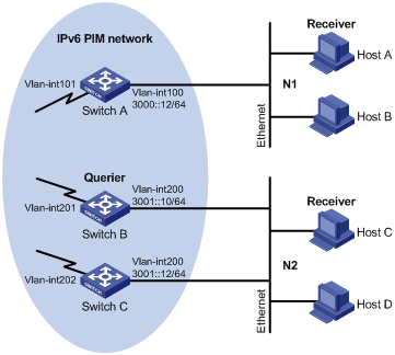
As shown in Figure 7, receivers receive VOD information in the multicast mode. Receivers of different organizations form stub networks N1 and N2, and Host A in N1 and Host C in N2 are multicast receivers.
Switch A in the IPv6 PIM network connects to N1, and Switch B and Switch C connect to N2. Switch A connects to N1 through VLAN-interface 100, and to other devices in the IPv6 PIM network through VLAN-interface 101.
MLDv1 runs between Switch A and N1. MLDv1 runs between the other two switches (Switch B and Switch C) and N2. Switch B acts as the MLD querier because it has a lower IPv6 address.
The hosts in N1 can join only IPv6 multicast group FF1E::101, and the hosts in N2 can join any IPv6 multicast groups.
Configuration procedure
1. Enable IPv6 forwarding on each switch and configure an IP address and prefix length for each interface as shown in Figure 7. (Details not shown.)
2. Configure OSPFv3 on the switches to make sure the network-layer is interoperable among the switches on the IPv6 PIM network and routing information between the switches can be dynamically updated. (Details not shown.)
3. Enable the IPv6 multicast routing, and enable IPv6 PIM-DM and MLD:
# Enable IPv6 multicast routing on Switch A, enable IPv6 PIM-DM on each interface, and enable MLD on VLAN-interface 100.
<SwitchA> system-view
[SwitchA] multicast ipv6 routing-enable
[SwitchA] interface vlan-interface 100
[SwitchA-Vlan-interface100] mld enable
[SwitchA-Vlan-interface100] pim ipv6 dm
[SwitchA-Vlan-interface100] quit
[SwitchA] interface vlan-interface 101
[SwitchA-Vlan-interface101] pim ipv6 dm
[SwitchA-Vlan-interface101] quit
# Enable IPv6 multicast routing on Switch B, enable IPv6 PIM-DM on each interface, and enable MLD on VLAN-interface 200.
<SwitchB> system-view
[SwitchB] multicast ipv6 routing-enable
[SwitchB] interface vlan-interface 200
[SwitchB-Vlan-interface200] mld enable
[SwitchB-Vlan-interface200] pim ipv6 dm
[SwitchB-Vlan-interface200] quit
[SwitchB] interface vlan-interface 201
[SwitchB-Vlan-interface201] pim ipv6 dm
[SwitchB-Vlan-interface201] quit
# Enable IPv6 multicast routing on Switch C, enable IPv6 PIM-DM on each interface, and enable MLD on VLAN-interface 200.
<SwitchC> system-view
[SwitchC] multicast ipv6 routing-enable
[SwitchC] interface vlan-interface 200
[SwitchC-Vlan-interface200] mld enable
[SwitchC-Vlan-interface200] pim ipv6 dm
[SwitchC-Vlan-interface200] quit
[SwitchC] interface vlan-interface 202
[SwitchC-Vlan-interface202] pim ipv6 dm
[SwitchC-Vlan-interface202] quit
4. Configure an IPv6 multicast group filter on Switch A, so that the hosts connected to VLAN-interface 100 can join IPv6 multicast group FF1E::101 only.
[SwitchA] acl ipv6 number 2001
[SwitchA-acl6-basic-2001] rule permit source ff1e::101 128
[SwitchA-acl6-basic-2001] quit
[SwitchA] interface vlan-interface 100
[SwitchA-Vlan-interface100] mld group-policy 2001
[SwitchA-Vlan-interface100] quit
Verifying the configuration
# Display MLD information on VLAN-interface 200 of Switch B.
[SwitchB] display mld interface vlan-interface 200
Vlan-interface200(FE80::200:5EFF:FE66:5100):
MLD is enabled
Current MLD version is 1
Value of query interval for MLD(in seconds): 125
Value of other querier present interval for MLD(in seconds): 255
Value of maximum query response time for MLD(in seconds): 10
Querier for MLD: FE80::200:5EFF:FE66:5100 (this router)
Total 1 MLD Group reported
MLD SSM mapping configuration example
Network requirements
As shown in Figure 8, the IPv6 PIM-SM domain applies both the ASM model and SSM model for IPv6 multicast delivery. Switch D's VLAN-interface 104 serves as the C-BSR and C-RP. The SSM group range is FF3E::/64.
MLDv2 runs on Switch D's VLAN-interface 400. The receiver host runs MLDv1, and does not support MLDv2. Therefore, the Receiver host cannot specify expected multicast sources in its membership reports.
Source 1, Source 2, and Source 3 send IPv6 multicast packets to multicast groups in the IPv6 SSM group range. You can configure the MLD SSM mapping feature on Switch D so that the receiver host will receive IPv6 multicast data from Source 1 and Source 3 only.
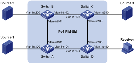
Table 3 Interface and IP address assignment
|
Device |
Interface |
IPv6 address |
Device |
Interface |
IPv6 address |
|
Source 1 |
— |
1001::1/64 |
Source 3 |
— |
3001::1/64 |
|
Source 2 |
— |
2001::1/64 |
Receiver |
— |
4001::1/64 |
|
Switch A |
Vlan-int100 |
1001::2/64 |
Switch C |
Vlan-int300 |
3001::2/64 |
|
Switch A |
Vlan-int101 |
1002::1/64 |
Switch C |
Vlan-int103 |
3002::1/64 |
|
Switch A |
Vlan-int104 |
1003::1/64 |
Switch C |
Vlan-int102 |
2002::2/64 |
|
Switch B |
Vlan-int200 |
2001::2/64 |
Switch D |
Vlan-int400 |
4001::2/64 |
|
Switch B |
Vlan-int101 |
1002::2/64 |
Switch D |
Vlan-int103 |
3002::2/64 |
|
Switch B |
Vlan-int102 |
2002::1/64 |
Switch D |
Vlan-int104 |
1003::2/64 |
Configuration procedure
1. Enable IPv6 forwarding on each switch and configure an IPv6 address and prefix length for each interface as shown in Figure 8. (Details not shown.)
2. Configure OSPFv3 on the switches to make sure the network-layer is interoperable on the IPv6 PIM-SM domain and routing information among the switches can be dynamically updated. (Details not shown.)
3. Enable IPv6 multicast routing, enable IPv6 PIM-SM on each interface and enable MLD and MLD SSM mapping on the host-side interface:
# Enable IPv6 multicast routing on Switch D, enable IPv6 PIM-SM on each interface, and enable MLD (version 2) and MLD SSM mapping on VLAN-interface 400.
<SwitchD> system-view
[SwitchD] multicast ipv6 routing-enable
[SwitchD] interface vlan-interface 400
[SwitchD-Vlan-interface400] mld enable
[SwitchD-Vlan-interface400] mld version 2
[SwitchD-Vlan-interface400] mld ssm-mapping enable
[SwitchD-Vlan-interface400] pim ipv6 sm
[SwitchD-Vlan-interface400] quit
[SwitchD] interface vlan-interface 103
[SwitchD-Vlan-interface103] pim ipv6 sm
[SwitchD-Vlan-interface103] quit
[SwitchD] interface vlan-interface 104
[SwitchD-Vlan-interface104] pim ipv6 sm
[SwitchD-Vlan-interface104] quit
# Enable IPv6 multicast routing on Switch A, and enable IPv6 PIM-SM on each interface.
<SwitchA> system-view
[SwitchA] multicast ipv6 routing-enable
[SwitchA] interface vlan-interface 100
[SwitchA-Vlan-interface100] pim ipv6 sm
[SwitchA-Vlan-interface100] quit
[SwitchA] interface vlan-interface 101
[SwitchA-Vlan-interface101] pim ipv6 sm
[SwitchA-Vlan-interface101] quit
[SwitchA] interface vlan-interface 104
[SwitchA-Vlan-interface104] pim ipv6 sm
[SwitchA-Vlan-interface104] quit
# Enable IPv6 multicast routing and IPv6 PIM-SM on Switch B and Switch C in the same way. (Details not shown.)
4. Configure C-BSR and C-RP interfaces on Switch D.
[SwitchD] pim ipv6
[SwitchD-pim6] c-bsr 1003::2
[SwitchD-pim6] c-rp 1003::2
[SwitchD-pim6] quit
5. Configure the IPv6 SSM group range:
# Configure the IPv6 SSM group range FF3E::/64 on Switch D.
[SwitchD] acl ipv6 number 2000
[SwitchD-acl6-basic-2000] rule permit source ff3e:: 64
[SwitchD-acl6-basic-2000] quit
[SwitchD] pim ipv6
[SwitchD-pim6] ssm-policy 2000
[SwitchD-pim6] quit
# Configure the IPv6 SSM group range on Switch A, Switch B, and Switch C in the same way. (Details not shown.)
6. Configure MLD SSM mappings on Switch D.
[SwitchD] mld
[SwitchD-mld] ssm-mapping ff3e:: 64 1001::1
[SwitchD-mld] ssm-mapping ff3e:: 64 3001::1
[SwitchD-mld] quit
Verifying the configuration
# Display the MLD SSM mapping information for IPv6 multicast group FF3E::101 on Switch D.
[SwitchD] display mld ssm-mapping ff3e::101
Group: FF3E::101
Source list:
1001::1
3001::1
# Display the IPv6 multicast group information created based on the configured MLD SSM mappings on Switch D.
[SwitchD] display mld ssm-mapping group
Total 1 MLD SSM-mapping Group(s).
Interface group report information
Vlan-interface400 (4001::2):
Total 1 MLD SSM-mapping Group reported
Group Address: FF3E::101
Last Reporter: 4001::1
Uptime: 00:02:04
Expires: off
# Display the IPv6 PIM routing table information on Switch D.
[SwitchD] display pim ipv6 routing-table
Total 0 (*, G) entry; 2 (S, G) entry
(1001::1, FF3E::101)
Protocol: pim-ssm, Flag:
UpTime: 00:13:25
Upstream interface: Vlan-interface104
Upstream neighbor: 1003::1
RPF prime neighbor: 1003::1
Downstream interface(s) information:
Total number of downstreams: 1
1: Vlan-interface400
Protocol: mld, UpTime: 00:13:25, Expires: -
(3001::1, FF3E::101)
Protocol: pim-ssm, Flag:
UpTime: 00:13:25
Upstream interface: Vlan-interface103
Upstream neighbor: 3002::1
RPF prime neighbor: 3002::1
Downstream interface(s) information:
Total number of downstreams: 1
1: Vlan-interface400
Protocol: mld, UpTime: 00:13:25, Expires: -
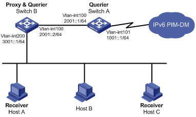
MLD proxying configuration example
Network requirements
As shown in Figure 9, IPv6 PIM-DM runs on the core network. Host A and Host C in the stub network receive VOD information destined to multicast group FF3E::101.
Configure the MLD proxying feature on Switch B so that Switch B can maintain group memberships and forward IPv6 multicast traffic without running IPv6 PIM-DM.
Configuration procedure
1. Enable IPv6 forwarding on each switch and configure the IPv6 address and prefix length of each interface as shown in Figure 9. (Details not shown.)
2. Enable IPv6 multicast routing, IPv6 PIM-DM, MLD, and MLD proxying:
# Enable IPv6 multicast routing on Switch A, IPv6 PIM-DM on VLAN-interface 101, and MLD on VLAN-interface 100.
<SwitchA> system-view
[SwitchA] multicast ipv6 routing-enable
[SwitchA] interface vlan-interface 101
[SwitchA-Vlan-interface101] pim ipv6 dm
[SwitchA-Vlan-interface101] quit
[SwitchA] interface vlan-interface 100
[SwitchA-Vlan-interface100] mld enable
[SwitchA-Vlan-interface100] pim ipv6 dm
[SwitchA-Vlan-interface100] quit
# Enable IPv6 multicast routing on Switch B, MLD proxying on VLAN-interface 100, and MLD on VLAN-interface 200.
<SwitchB> system-view
[SwitchB] multicast ipv6 routing-enable
[SwitchB] interface vlan-interface 100
[SwitchB-Vlan-interface100] mld proxying enable
[SwitchB-Vlan-interface100] quit
[SwitchB] interface vlan-interface 200
[SwitchB-Vlan-interface200] mld enable
[SwitchB-Vlan-interface200] quit
Verifying the configuration
# Display MLD configuration and operation information on VLAN-interface 100 of Switch B.
[SwitchB] display mld interface vlan-interface 100 verbose
Vlan-interface100(2001::2):
MLD proxy is enabled
Current MLD version is 1
Multicast routing on this interface: enabled
Require-router-alert: disabled
# Display the MLD group information on Switch A.
[SwitchA] display mld group
Total 1 MLD Group(s).
Interface group report information
Vlan-interface100(2001::1):
Total 1 MLD Groups reported
Group Address Last Reporter Uptime Expires
ff3e::101 2001::2 00:02:04 00:01:15
The output shows that the MLD reports sent from the hosts are forwarded to Switch A through the proxy interface, VLAN-interface 100 of Switch B.
Troubleshooting MLD
No member information exists on the receiver-side router
Symptom
When a host sends a message to announce its joining IPv6 multicast group G, no member information of multicast group G exists on the intermediate router.
Analysis
· The correctness of networking and interface connections and whether the protocol layer of the interface is up directly affect the generation of IPv6 group member information.
· IPv6 multicast routing must be enabled on the router and MLD must be enabled on the interface connecting to the host.
· If the MLD version on the router interface is lower than that on the host, the router will not be able to recognize the MLD report from the host.
· If the mld group-policy command has been configured on an interface, the interface cannot receive report messages that fail to pass filtering.
Solution
1. Use the display mld interface command to verify that the networking, interface connections, and IP address configuration are correct. If no information is output, the interface is in an abnormal state. This is usually because you have configured the shutdown command on the interface, the interface is not correctly connected, or the IPv6 address configuration is not correctly done.
2. Use the display current-configuration command to verify that the multicast ipv6 routing-enable command has been executed. If not, use the multicast ipv6 routing-enable command in system view to enable IPv6 multicast routing. In addition, enable MLD on the corresponding interface.
3. Use the display mld interface command to verify that the MLD version on the interface is lower than that on the host.
4. Use the display current-configuration interface command to verify that no ACL rule has been configured to restrict the host from joining IPv6 multicast group G. If an IPv6 ACL is configured to restrict the host from joining IPv6 multicast group G, the ACL must be modified to allow IPv6 multicast group G to receive report messages.
Inconsistent memberships on routers on the same subnet
Symptom
Different memberships are maintained on different MLD routers on the same subnet.
Analysis
· A router running MLD maintains multiple parameters for each interface, and these parameters influence one another, forming very complicated relationships. Inconsistent MLD interface parameter configurations for routers on the same subnet will surely result in inconsistent MLD memberships.
· Two MLD versions are available. Although routers running different MLD versions are compatible with hosts, all routers on the same subnet must run the same MLD version. Inconsistent MLD versions running on routers on the same subnet will also lead to inconsistent MLD memberships.
Solution
1. Use the display current-configuration command to verify the MLD configuration information on the interface.
2. Use the display mld interface command on all routers on the same subnet to check the MLD timers for inconsistent configurations.
3. Use the display mld interface command to verify that the routers are running the same MLD version.