- Table of Contents
-
- 08-IP Multicast Configuration Guide
- 00-Preface
- 01-Multicast Overview
- 02-IGMP Snooping Configuration
- 03-PIM Snooping Configuration
- 04-Multicast VLAN Configuration
- 05-Multicast Routing and Forwarding Configuration
- 06-IGMP Configuration
- 07-PIM Configuration
- 08-MSDP Configuration
- 09-MBGP Configuration
- 10-Multicast VPN Configuration
- 11-MLD Snooping Configuration
- 12-IPv6 PIM Snooping Configuration
- 13-IPv6 Multicast VLAN Configuration
- 14-IPv6 Multicast Routing and Forwarding Configuration
- 15-MLD Configuration
- 16-IPv6 PIM Configuration
- 17-IPv6 MBGP Configuration
- Related Documents
-
| Title | Size | Download |
|---|---|---|
| 07-PIM Configuration | 956.45 KB |
Contents
Administrative scoping overview
Relationship among PIM protocols
PIM-DM configuration task list
Enabling state-refresh capability
Configuring state-refresh parameters
Configuring PIM-DM graft retry period
PIM-SM configuration task list
Configuring administrative scoping
Configuring multicast source registration
BIDIR-PIM configuration task list
Configuring administrative scoping
PIM-SSM configuration task list
Configuring the SSM group range
Configuring PIM common features
PIM common feature configuration task list
Configuring a multicast data filter
Configuring a hello message filter
Configuring join/prune message sizes
Displaying and maintaining PIM
PIM-SM non-scoped zone configuration example
PIM-SM admin-scoped zone configuration example
BIDIR-PIM configuration example
A multicast distribution tree cannot be built correctly
Multicast data is abnormally terminated on an intermediate router
An RPT cannot be established or a source cannot register in PIM-SM
Overview
Protocol Independent Multicast (PIM) provides IP multicast forwarding by leveraging unicast static routes or unicast routing tables generated by any unicast routing protocol, such as RIP, OSPF, IS-IS, or BGP. Independent of the unicast routing protocols running on the device, multicast routing can be implemented as long as the corresponding multicast routing entries are created through unicast routes. PIM uses the reverse path forwarding (RPF) mechanism to implement multicast forwarding. When a multicast packet arrives on an interface of the device, it undergoes an RPF check. If the RPF check succeeds, the device creates the corresponding routing entry and forwards the packet. If the RPF check fails, the device discards the packet. For more information about RPF, see "Configuring multicast routing and forwarding."
Based on the implementation mechanism, PIM includes the following categories:
· Protocol Independent Multicast–Dense Mode (PIM-DM)
· Protocol Independent Multicast–Sparse Mode (PIM-SM)
· Bidirectional Protocol Independent Multicast (BIDIR-PIM)
· Protocol Independent Multicast Source-Specific Multicast (PIM-SSM)
The term "router" in this document refers to both routers and Layer 3 switches.
PIM-DM overview
PIM-DM is a type of dense mode multicast protocol. It uses the push mode for multicast forwarding, and is suitable for small-sized networks with densely distributed multicast members.
The basic implementation of PIM-DM is as follows:
· PIM-DM assumes that at least one multicast group member exists on each subnet of a network, and therefore multicast data is flooded to all nodes on the network. Then, branches without multicast forwarding are pruned from the forwarding tree, leaving only those branches that contain receivers. This flood-and-prune process takes place periodically. That is, pruned branches resume multicast forwarding when the pruned state times out and then data is flooded again down these branches, and then the branches are pruned again.
· When a new receiver on a previously pruned branch joins a multicast group, to reduce the join latency, PIM-DM uses a graft mechanism to resume data forwarding to that branch.
Generally speaking, the multicast forwarding path is a source tree, also known as a forwarding tree with the multicast source as its "root" and multicast group members as its "leaves." Because the source tree is the shortest path from the multicast source to the receivers, it is also called a shortest path tree (SPT).
The operating mechanism of PIM-DM is summarized as follows:
· Neighbor discovery
· SPT building
· Graft
Neighbor discovery
In a PIM domain, a PIM router discovers PIM neighbors, maintains PIM neighboring relationships with other routers, and builds and maintains SPTs by periodically multicasting hello messages to all other PIM routers (224.0.0.13) on the local subnet.
Every PIM-enabled interface on a router sends hello messages periodically, and thus learns the PIM neighboring information pertinent to the interface.
SPT building
The process of building an SPT is the flood-and-prune process.
1. In a PIM-DM domain, when a multicast source S sends multicast data to multicast group G, the multicast packet is first flooded throughout the domain. The router first performs RPF check on the multicast packet. If the packet passes the RPF check, the router creates an (S, G) entry and forwards the data to all downstream nodes in the network. In the flooding process, an (S, G) entry is created on all the routers in the PIM-DM domain.
2. Then, nodes without receivers downstream are pruned. A router having no receivers downstream sends a prune message to the upstream node to "tell" the upstream node to delete the corresponding interface from the outgoing interface list in the (S, G) entry and stop forwarding subsequent packets addressed to that multicast group down to this node.
|
|
NOTE: · An (S, G) entry contains the multicast source address S, multicast group address G, outgoing interface list, and incoming interface. · For a given multicast stream, the interface that receives the multicast stream is referred to as "upstream", and the interfaces that forward the multicast stream are referred to as "downstream." |
A prune process is first initiated by a leaf router. As shown in Figure 1, a router without any receiver attached to it (the router connected with Host A, for example) sends a prune message, and this prune process goes on until only necessary branches are left in the PIM-DM domain. These branches constitute the SPT.
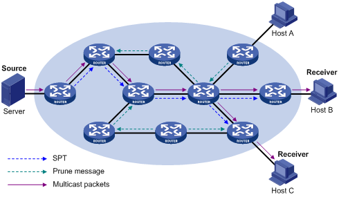
The flood-and-prune process takes place periodically. A pruned state timeout mechanism is provided. A pruned branch restarts multicast forwarding when the pruned state times out and then is pruned again when it no longer has any multicast receiver.
Graft
When a host attached to a pruned node joins a multicast group, to reduce the join latency, PIM-DM uses a graft mechanism to resume data forwarding to that branch. The process is as follows:
1. The node that needs to receive multicast data sends a graft message toward its upstream node, as a request to join the SPT again.
2. After receiving this graft message, the upstream node puts the interface on which the graft was received into the forwarding state and responds with a graft-ack message to the graft sender.
Assert
The assert mechanism shuts off duplicate multicast flows onto the same multi-access network, where more than one multicast router exists, by electing a unique multicast forwarder on the multi-access network.
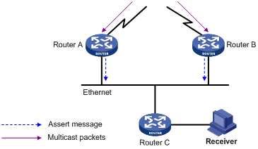
As shown in Figure 2, after Router A and Router B receive an (S, G) packet from the upstream node, they forward the packet to the local subnet. As a result, the downstream node Router C receives two identical multicast packets, and both Router A and Router B, on their own downstream interfaces, receive a duplicate packet forwarded by the other. After detecting this condition, both routers send an assert message to all PIM routers (224.0.0.13) on the local subnet through the interface that received the packet. The assert message contains the multicast source address (S), the multicast group address (G), and the preference and metric of the unicast route/MBGP route/multicast static route to the source. By comparing these parameters, either Router A or Router B becomes the unique forwarder of the subsequent (S, G) packets on the multi-access subnet. The comparison process is as follows:
1. The router with a higher preference to the source wins.
2. If both routers have the same preference to the source, the router with a smaller metric to the source wins.
3. If a tie exists in route metric to the source, the router with a higher IP address on the downstream interface wins.
PIM-SM overview
PIM-DM uses the flood-and-prune principle to build SPTs for multicast data distribution. Although an SPT has the shortest path, it is built with a low efficiency. Therefore the PIM-DM mode is not suitable for large- and medium-sized networks.
PIM-SM is a type of sparse mode multicast protocol. It uses the pull mode for multicast forwarding, and is suitable for large-sized and medium-sized networks with sparsely and widely distributed multicast group members.
The basic implementation of PIM-SM is as follows:
· PIM-SM assumes that no hosts need to receive multicast data. In the PIM-SM mode, routers must specifically request a particular multicast stream before the data is forwarded to them. The core task for PIM-SM to implement multicast forwarding will build and maintain rendezvous point trees (RPTs). An RPT is rooted at a router in the PIM domain as the common node, or rendezvous point (RP), through which the multicast data travels along the RPT and reaches the receivers.
· When a receiver is interested in the multicast data addressed to a specific multicast group, the router connected to this receiver sends a join message to the RP that corresponds to that multicast group. The path along which the message goes hop by hop to the RP forms a branch of the RPT.
· When a multicast source sends multicast streams to a multicast group, the source-side designated router (DR) first registers the multicast source with the RP by sending register messages to the RP by unicast until it receives a register-stop message from the RP. The arrival of a register message at the RP triggers the establishment of an SPT. Then, the multicast source sends subsequent multicast packets along the SPT to the RP. After reaching the RP, the multicast packet is duplicated and delivered to the receivers along the RPT.
|
|
NOTE: Multicast traffic is duplicated only where the distribution tree branches, and this process automatically repeats until the multicast traffic reaches the receivers. |
The operating mechanism of PIM-SM is summarized as follows:
· Neighbor discovery
· DR election
· RP discovery
· RPT building
· Multicast source registration
· Switchover to SPT
· Assert
Neighbor discovery
PIM-SM uses a similar neighbor discovery mechanism as PIM-DM does. For more information, see "Neighbor discovery."
DR election
PIM-SM also uses hello messages to elect a DR for a multi-access network (such as Ethernet). The elected DR will be the only multicast forwarder on this multi-access network.
A DR must be elected in a multi-access network, no matter this network connects to multicast sources or to receivers. The receiver-side DR sends join messages to the RP, and the source-side DR sends register messages to the RP.
A DR is elected on a multi-access subnet by means of comparison of the priorities and IP addresses carried in hello messages. An elected DR is substantially meaningful to PIM-SM. PIM-DM itself does not require a DR. However, if IGMPv1 runs on any multi-access network in a PIM-DM domain, a DR must be elected to act as the IGMPv1 querier on that multi-access network.
IGMP must be enabled on a device that acts as a receiver-side DR before receivers attached to this device can join multicast groups through this DR. For more information about IGMP, see "Configuring IGMP."
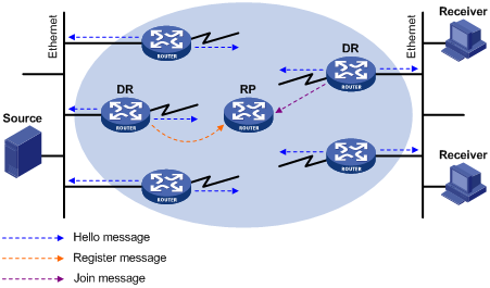
As shown in Figure 3, the DR election process is as follows:
1. Routers on the multi-access network send hello messages to one another. The hello messages contain the router priority for DR election. The router with the highest DR priority will become the DR.
2. In the case of a tie in the router priority, or if any router in the network does not support carrying the DR-election priority in hello messages, the router with the highest IP address will win the DR election.
When the DR fails, a timeout in receiving hello message triggers a new DR election process among the other routers.
RP discovery
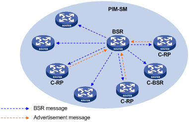
The RP is the core of a PIM-SM domain. For a small-sized, simple network, one RP is enough for forwarding information throughout the network, and you can statically specify the position of the RP on each router in the PIM-SM domain. In most cases, however, a PIM-SM network covers a wide area and a huge amount of multicast traffic must be forwarded through the RP. To lessen the RP burden and optimize the topological structure of the RPT, you can configure multiple candidate RPs (C-RPs) in a PIM-SM domain, among which an RP is dynamically elected through the bootstrap mechanism. Each elected RP provides services for a different multicast group range. For this purpose, you must configure a bootstrap router (BSR). The BSR serves as the administrative core of the PIM-SM domain. A PIM-SM domain can have only one BSR, but can have multiple candidate-BSRs (C-BSRs). If the BSR fails, a new BSR is automatically elected from the C-BSRs to avoid service interruption.
|
|
NOTE: · An RP can provide services for multiple multicast groups or all multicast groups. Only one RP can provide services for a given multicast group at a time. · A device can serve as a C-RP and a C-BSR at the same time. |
As shown in Figure 4, each C-RP periodically unicasts its advertisement messages (C-RP-Adv messages) to the BSR. A C-RP-Adv message contains the address of the advertising C-RP and the multicast group range to which it is designated. The BSR collects these advertisement messages and chooses the appropriate C-RP information for each multicast group to form an RP-set, which is a database of mappings between multicast groups and RPs. The BSR then encapsulates the RP-set in the bootstrap messages (BSMs) that it periodically originates and floods the bootstrap messages to the entire PIM-SM domain.
Based on the information in the RP-sets, all routers in the network can calculate the location of the corresponding RPs based on the following rules:
1. The C-RP with the highest priority wins.
2. If all the C-RPs have the same priority, their hash values are calculated through the hashing algorithm. The C-RP with the largest hash value wins.
3. If all the C-RPs have the same priority and hash value, the C-RP with the highest IP address wins.
The hashing algorithm used for RP calculation is "Value (G, M, Ci) = (1103515245 * ( (1103515245 * (G & M) + 12345) XOR Ci) + 12345) mod 231."
Table 1 Values in the hashing algorithm
|
Value |
Description |
|
Value |
Hash value. |
|
G |
IP address of the multicast group. |
|
M |
Hash mask length. |
|
Ci |
IP address of the C-RP. |
|
& |
Logical operator of "and." |
|
XOR |
Logical operator of "exclusive-or." |
|
Mod |
Modulo operator, which gives the remainder of an integer division. |
RPT building
Figure 5 RPT building in a PIM-SM domain
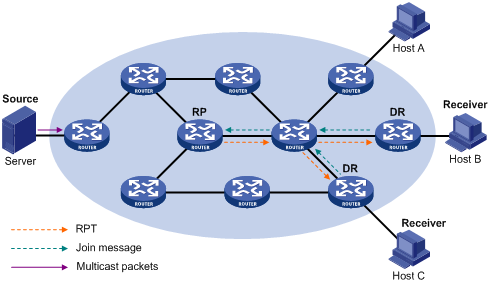
As shown in Figure 5, the process of building an RPT is as follows:
1. When a receiver joins multicast group G, it uses an IGMP message to inform the directly connected DR.
2. After getting the receiver information, the DR sends a join message, which is forwarded hop by hop to the RP that corresponds to the multicast group.
3. The routers along the path from the DR to the RP form an RPT branch. Each router on this branch generates a (*, G) entry in its forwarding table. The asterisk (*) means any multicast source. The RP is the root, and the DRs are the leaves, of the RPT.
The multicast data addressed to the multicast group G flows through the RP, reaches the corresponding DR along the established RPT, and finally is delivered to the receiver.
When a receiver is no longer interested in the multicast data addressed to multicast group G, the directly connected DR sends a prune message, which goes hop by hop along the RPT to the RP. After receiving the prune message, the upstream node deletes the interface that connects to this downstream node from the outgoing interface list and determines whether it itself has receivers for that multicast group. If not, the router continues to forward the prune message to its upstream router.
Multicast source registration
The purpose of multicast source registration will inform the RP about the existence of the multicast source.
Figure 6 Multicast source registration
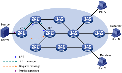
As shown in Figure 6, the multicast source registers with the RP as follows:
1. When the multicast source S sends the first multicast packet to multicast group G, the DR directly connected with the multicast source —after receiving the multicast packet, encapsulates the packet in a PIM register message, and sends the message to the corresponding RP by unicast.
2. When the RP receives the register message, it extracts the multicast packet from the register message and forwards the multicast packet down the RPT, and sends an (S, G) join message hop by hop toward the multicast source. Thus, the routers along the path from the RP to the multicast source constitute an SPT branch. Each router on this branch generates an (S, G) entry in its forwarding table. The source-side DR is the root, and the RP is the leaf, of the SPT.
3. The subsequent multicast data from the multicast source travels along the established SPT to the RP, and then the RP forwards the data along the RPT to the receivers. When the multicast traffic arrives at the RP along the SPT, the RP sends a register-stop message to the source-side DR by unicast to stop the source registration process.
|
|
NOTE: The RP is configured to initiate a switchover to SPT as described in this section. Otherwise, the source-side DR keeps encapsulating multicast data in register messages and the registration process will not stop unless no outgoing interfaces exist in the (S, G) entry on the RP. |
Switchover to SPT
In a PIM-SM domain, a multicast group corresponds to one RP and RPT. Before the switchover to SPT occurs, the source-side DR encapsulates all multicast data destined to the multicast group in register messages and sends these messages to the RP. After receiving these register messages, the RP extracts the multicast data and sends the multicast data down the RPT to the DRs at the receiver side. The RP acts as a transfer station for all multicast packets. The whole process involves the following issues:
· The source-side DR and the RP need to implement complicated encapsulation and de-encapsulation of multicast packets.
· Multicast packets are delivered along a path that might not be the shortest one.
· An increase in multicast traffic adds a great burden on the RP, increasing the risk of failure.
To solve the issues, PIM-SM allows an RP or the DR at the receiver side to initiate the following switchover to SPT process:
1. The RP initiates a switchover to SPT process.
After receiving the first multicast packet, the RP sends an (S, G) join message hop by hop toward the multicast source to establish an SPT between the DR at the source side and the RP. The subsequent multicast data from the multicast source travels along the established SPT to the RP.
For more information about the switchover to SPT initiated by the RP, see "Multicast source registration."
2. The receiver-side DR initiates a switchover to SPT process.
After receiving the first multicast packet, the receiver-side DR initiates a switchover to SPT process, as follows:
¡ The receiver-side DR sends an (S, G) join message hop by hop toward the multicast source. When the join message reaches the source-side DR, all the routers on the path have installed the (S, G) entry in their forwarding table, and thus an SPT branch is established.
¡ When the multicast packets travel to the router where the RPT and the SPT deviate, the router drops the multicast packets received from the RPT and sends an RP-bit prune message hop by hop to the RP. After receiving this prune message, the RP sends a prune message toward the multicast source (suppose only one receiver exists). Thus, switchover to SPT is completed.
¡ Multicast data is directly sent from the source to the receivers along the SPT.
PIM-SM builds SPTs through switchover to SPT more economically than PIM-DM does through the flood-and-prune mechanism.
Assert
PIM-SM uses a similar assert mechanism as PIM-DM does. For more information, see "Assert."
BIDIR-PIM overview
In some many-to-many applications, such as multi-side video conference, there might be multiple receivers interested in multiple multicast sources simultaneously. With PIM-DM or PIM-SM, each router along the SPT must create an (S, G) entry for each multicast source, consuming a lot of system resources.
BIDIR-PIM addresses the problem. Derived from PIM-SM, BIDIR-PIM builds and maintains bidirectional RPTs, each of which is rooted at an RP and connects multiple multicast sources with multiple receivers. Traffic from the multicast sources is forwarded through the RPs to the receivers along the bidirectional RPTs. Each router needs to maintain only one (*, G) multicast routing entry, saving system resources.
BIDIR-PIM is suitable for networks with dense multicast sources and dense receivers.
The operating mechanism of BIDIR-PIM is summarized as follows:
· Neighbor discovery
· RP discovery
· DF election
· Bidirectional RPT building
Neighbor discovery
BIDIR-PIM uses the same neighbor discovery mechanism as PIM-SM does. For more information, see "Neighbor discovery."
RP discovery
BIDIR-PIM uses the same RP discovery mechanism as PIM-SM does. For more information, see "RP discovery."
In PIM-SM, an RP must be specified with a real IP address. In BIDIR-PIM, however, an RP can be specified with a virtual IP address, which is called the rendezvous point address (RPA). The link corresponding to the RPA's subnet is called the rendezvous point link (RPL). All interfaces connected to the RPL can act as the RP, and they back up one another.
|
|
NOTE: In BIDIR-PIM, an RPF interface is the interface pointing to an RP, and an RPF neighbor is the address of the next hop to the RP. |
DF election
On a network segment with multiple multicast routers, duplicate multicast packets might be forwarded to the RP. To address this issue, BIDIR-PIM uses a DF election mechanism to elect a unique designated forwarder (DF) for each RP on every network segment within the BIDIR-PIM domain, and allows only the DF to forward multicast data to the RP.
|
|
NOTE: DF election is not necessary for an RPL. |
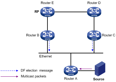
As shown in Figure 7, without the DF election mechanism, both Router B and Router C can receive multicast packets from Route A, and they might both forward the packets to downstream routers on the local subnet. As a result, the RP (Router E) receives duplicate multicast packets. With the DF election mechanism, once receiving the RP information, Router B and Router C initiate a DF election process for the RP:
1. Router B and Router C multicast DF election messages to all PIM routers (224.0.0.13). The election messages carry the RP's address, and the priority and metric of the unicast route, MBGP route, or multicast static route to the RP.
2. The router with a route of the highest priority becomes the DF.
3. In the case of a tie, the router with the route with the lowest metric wins the DF election.
4. In the case of a tie in the metric, the router with the highest IP address wins.
Bidirectional RPT building
A bidirectional RPT comprises a receiver-side RPT and a source-side RPT. The receiver-side RPT is rooted at the RP and takes the routers directly connected to the receivers as leaves. The source-side RPT is also rooted at the RP but takes the routers directly connected to the sources as leaves. The processes for building these two parts are different.
Figure 8 RPT building at the receiver side

As shown in Figure 8, the process for building a receiver-side RPT is similar to that for building an RPT in PIM-SM:
1. When a receiver joins multicast group G, it uses an IGMP message to inform the directly connected router.
2. After getting the receiver information, the router sends a join message, which is forwarded hop by hop to the RP of the multicast group.
3. The routers along the path from the receiver's directly connected router to the RP form an RPT branch, and each router on this branch adds a (*, G) entry to its forwarding table. The asterisk (*) means any multicast source.
When a receiver is no longer interested in the multicast data addressed to multicast group G, the directly connected router sends a prune message, which goes hop by hop along the reverse direction of the RPT to the RP. After receiving the prune message, each upstream node deletes the interface connected to the downstream node from the outgoing interface list and checks whether it has receivers in that multicast group. If not, the router continues to forward the prune message to its upstream router.
Figure 9 RPT building at the multicast source side
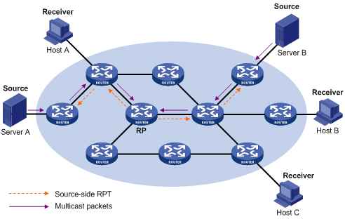
As shown in Figure 9, the process for building a source-side RPT is relatively simple:
1. When a multicast source sends multicast packets to multicast group G, the DF in each network segment unconditionally forwards the packets to the RP.
2. The routers along the path from the source's directly connected router to the RP form an RPT branch. Each router on this branch adds a (*, G) entry to its forwarding table. The asterisk (*) means any multicast source.
After a bidirectional RPT is built, multicast traffic is forwarded along the source-side RPT and receiver-side RPT from sources to receivers.
|
|
NOTE: If a receiver and a multicast source are at the same side of the RP, the source-side RPT and the receiver-side RPT might meet at a node before reaching the RP. In this case, multicast packets are directly forwarded by the node to the receiver, instead of by the RP. |
Administrative scoping overview
Division of PIM-SM domains
Typically, a PIM-SM domain or BIDIR-PIM domain contains only one BSR, which is responsible for advertising RP-set information within the entire PIM-SM/BIDIR-PIM domain. The information for all multicast groups is forwarded within the network scope that the BSR administers. This is called the "non-scoped BSR mechanism."
To implement refined management, you can divide a PIM-SM domain or BIDIR-PIM domain into one global-scoped zone and multiple administratively scoped zones (admin-scoped zones). This is called the "administrative scoping mechanism."
The administrative scoping mechanism effectively releases stress on the management in a single-BSR domain and enables provision of zone-specific services through private group addresses.
Admin-scoped zones are divided specific to multicast groups. Zone border routers (ZBRs) form the boundary of the admin-scoped zone. Each admin-scoped zone maintains one BSR to provide services for multicast groups within a specific range. Multicast protocol packets, such as assert messages and bootstrap messages, for a specific group range cannot cross the admin-scoped zone boundary. Multicast group ranges to which different admin-scoped zones are designated can be overlapped. A multicast group is valid only within its local admin-scoped zone, and functions as a private group address.
The global-scoped zone maintains a BSR to provide services for the multicast groups that do not belong to any admin-scoped zone.
Relationship between admin-scoped zones and the global-scoped zone
The global-scoped zone and each admin-scoped zone have their own C-RPs and BSRs. These devices are effective only in their respective zones. BSR election and RP election are implemented independently within each admin-scoped zone. Each admin-scoped zone has its own boundary. The multicast information cannot cross this border in either direction. A better understanding of the global-scoped zone and admin-scoped zones should be based on geographical space and group address range.
· In view of geographical space:
Admin-scoped zones are logical zones specific to particular multicast groups. The multicast packets of these multicast groups are confined within the local admin-scoped zone and cannot cross the boundary of the zone.
Figure 10 Relationship between admin-scoped zones and the global-scoped zone in geographic space
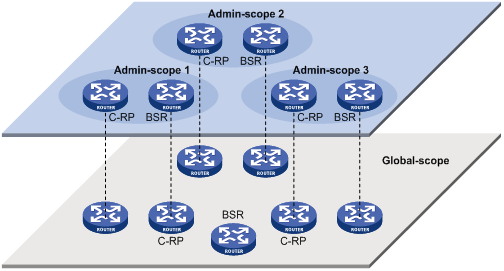
As shown in Figure 10, for multicast groups in the same address range, admin-scoped zones must be geographically separated from one another. A router must not provide services for different admin-scoped zones. Different admin-scoped zones contain different routers, whereas the global-scoped zone covers all routers in the PIM-SM/BIDIR-PIM domain. Multicast packets that do not belong to any admin-scoped zones can be transmitted in the entire PIM-SM/BIDIR-PIM domain.
· In view of multicast group address ranges:
Each admin-scoped zone serves specific multicast groups. Usually, these addresses have no intersections; however, they might overlap one another.
Figure 11 Relationship between admin-scoped zones and the global-scoped zone in group address ranges
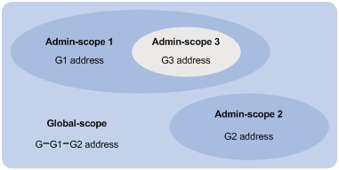
In Figure 11, the group address ranges of admin-scoped 1 and 2 have no intersection, whereas the group address range of admin-scoped 3 is a subset of the address range of admin-scoped 1. The group address range of the global-scoped zone covers all the group addresses other than those of all the admin-scoped zones. That is, the group address range of the global-scoped zone is G-G1-G2. A supplementary relationship exists between the global-scoped zone and all the admin-scoped zones in terms of group address ranges.
PIM-SSM overview
The source-specific multicast (SSM) model and the any-source multicast (ASM) model are opposites. Currently, the ASM model includes the PIM-DM and PIM-SM modes. The SSM model can be implemented by leveraging part of the PIM-SM technique. It is also called "PIM-SSM."
The SSM model provides a solution for source-specific multicast. It maintains the relationships between hosts and routers through IGMPv3.
In actual application, part of IGMPv3 or PIM-SM technique is adopted to implement the SSM model. In the SSM model, receivers locate a multicast source by means of advertisements, consultancy, and so on. Therefore, no RP is needed, no RPT is required, no source registration process exists, and the multicast source discovery protocol (MSDP) is not needed for discovering sources in other PIM domains.
The operating mechanism of PIM-SSM is summarized as follows:
· Neighbor discovery
· DR election
· SPT building
In PIM-SSM, the term "channel" refers to a multicast group, and the term "channel subscription" refers to a join message.
Neighbor discovery
PIM-SSM uses the same neighbor discovery mechanism as in PIM-DM and PIM-SM. See "Neighbor discovery."
DR election
PIM-SSM uses the same DR election mechanism as in PIM-SM. See "DR election."
Construction of SPT
Whether to build an RPT for PIM-SM or an SPT for PIM-SSM depends on whether the multicast group the receiver will join is in the SSM group range. (SSM group range reserved by IANA is 232.0.0.0/8.)
Figure 12 SPT building in PIM-SSM
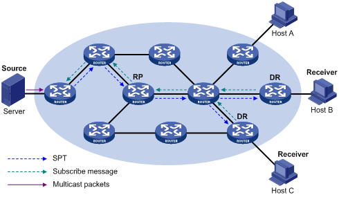
As shown in Figure 12, Host B and Host C are multicast information receivers. They send IGMPv3 report messages to the respective DRs to express their interest in a specific multicast source S.
After receiving a report message, the DR first determines whether the group address in this message is in the SSM group range:
· If so, the DR sends a subscribe message for channel subscription hop by hop toward the multicast source S. An (S, G) entry is created on all routers on the path from the DR to the source. Thus, an SPT is built in the network, with the source S as its root and receivers as its leaves. This SPT is the transmission channel in PIM-SSM.
· If not, the DR follows the PIM-SM process. The receiver-side DR sends a (*, G) join message to the RP, and the source-side DR starts a multicast source registration process.
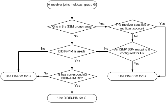
Relationship among PIM protocols
In a PIM network, PIM-DM cannot run together with PIM-SM, BIDIR-PIM, or PIM-SSM. However, PIM-SM, BIDIR-PIM, and PIM-SSM can run together. When they run together, which one is chosen for a receiver trying to join a group depends, as shown in Figure 13.
For more information about IGMP SSM mapping, see "Configuring IGMP."
Figure 13 Relationship among PIM protocols
PIM support for VPNs
|
|
CAUTION: When the system is operating in standard mode, a reserved VLAN must be configured if you want to configure PIM support for VPNs. Otherwise, abnormality might occur in the system. After a reserved VLAN is configured, any change to it will incur reconfiguration of the reserved VLAN. For information about the system operating mode, see Fundamentals Configuration Guide. For information about how to configure a reserved VLAN, see MPLS Configuration Guide and MPLS Command Reference. |
To support PIM for VPNs, a multicast router that runs PIM maintains an independent set of PIM neighbor table, multicast routing table, BSR information, and RP-set information for each VPN.
After receiving a multicast data packet, the multicast router checks to which VPN the data packet belongs, and then forwards the packet according to the multicast routing table for that VPN or creates a multicast routing entry for that VPN.
Protocols and standards
· RFC 3973, Protocol Independent Multicast-Dense Mode (PIM-DM): Protocol Specification(Revised)
· RFC 4601, Protocol Independent Multicast-Sparse Mode (PIM-SM): Protocol Specification (Revised)
· RFC 5015, Bidirectional Protocol Independent Multicast (BIDIR-PIM)
· RFC 5059, Bootstrap Router (BSR) Mechanism for Protocol Independent Multicast (PIM)
· RFC 4607, Source-Specific Multicast for IP
· Draft-ietf-ssm-overview-05, An Overview of Source-Specific Multicast (SSM)
Configuring PIM-DM
PIM-DM configuration task list
|
Task |
Remarks |
|
Required. |
|
|
Optional. |
|
|
Optional. |
|
|
Optional. |
|
|
Optional. |
Configuration prerequisites
Before you configure PIM-DM, complete the following tasks:
· Configure any unicast routing protocol so that all devices in the domain are interoperable at the network layer.
· Determine the interval between state-refresh messages.
· Determine the minimum time to wait before receiving a new refresh message.
· Determine the TTL value of state-refresh messages.
· Determine the graft retry period.
Enabling PIM-DM
With PIM-DM enabled, a router sends hello messages periodically to discover PIM neighbors and processes messages from the PIM neighbors. When you deploy a PIM-DM domain, enable PIM-DM on all non-border interfaces of the routers.
Configuration guidelines
· When the system is operating in standard mode, you must configure a reserved VLAN before you configure PIM-DM for a VPN instance. For more information about the system operating mode, see Fundamentals Configuration Guide. For more information about a reserved VLAN, see MPLS Configuration Guide and MPLS Command Reference.
· All the interfaces of a switch that are in the same VPN instance must share the same PIM mode.
· PIM-DM does not work with multicast groups in the SSM group range.
Configuration procedure
To enable PIM-DM globally on the public network:
|
Step |
Command |
Remarks |
|
1. Enter system view. |
system-view |
N/A |
|
2. Enable IP multicast routing. |
multicast routing-enable |
Disable by default. |
|
3. Enter interface view. |
interface interface-type interface-number |
N/A |
|
4. Enable PIM-DM. |
pim dm |
Disabled by default. |
To enable PIM-DM in a VPN instance:
|
Step |
Command |
Description |
|
1. Enter system view. |
system-view |
N/A |
|
2. Create a VPN instance and enter VPN instance view. |
ip vpn-instance vpn-instance-name |
N/A |
|
3. Configure a route-distinguisher (RD) for the VPN instance. |
route-distinguisher route-distinguisher |
Not configured by default. |
|
4. Enable IP multicast routing. |
multicast routing-enable |
Disabled by default. |
|
5. Enter interface view. |
interface interface-type interface-number |
N/A |
|
6. Bind the interface with a VPN instance. |
ip binding vpn-instance vpn-instance-name |
By default, an interface belongs to the public network, and is not bound with any VPN instance. |
|
7. Enable PIM-DM. |
pim dm |
Disabled by default. |
For more information about the ip vpn-instance, route-distinguisher, and ip binding vpn-instance commands, see MPLS Command Reference.
Enabling state-refresh capability
Pruned interfaces resume multicast forwarding when the pruned state times out. To prevent this, the router with the multicast source attached periodically sends an (S, G) state-refresh message, which is forwarded hop by hop along the initial multicast flooding path of the PIM-DM domain, to refresh the prune timer state of all the routers on the path. A multi-access subnet can have the state-refresh capability only if the state-refresh capability is enabled on all PIM routers on the subnet.
To enable the state-refresh capability:
|
Step |
Command |
Remarks |
|
1. Enter system view. |
system-view |
N/A |
|
2. Enter interface view. |
interface interface-type interface-number |
N/A |
|
3. Enable the state-refresh capability. |
pim state-refresh-capable |
Optional. Enabled by default. |
Configuring state-refresh parameters
The router directly connected with the multicast source periodically sends state-refresh messages. You can configure the interval for sending such messages.
A router might receive multiple state-refresh messages within a short time, of which some might be duplicated messages. To keep a router from receiving such duplicated messages, you can configure the time that the router must wait before it receives next state-refresh message. If the router receives a new state-refresh message within the waiting time, it discards the message. If this timer times out, the router will accept a new state-refresh message, refresh its own PIM-DM state, and reset the waiting timer.
The TTL value of a state-refresh message decrements by 1 whenever it passes a router before it is forwarded to the downstream node until the TTL value comes down to 0. In a small network, a state-refresh message might cycle in the network. To effectively control the propagation scope of state-refresh messages, configure an appropriate TTL value based on the network size.
Perform the following configurations on all routers in the PIM domain.
To configure state-refresh parameters:
|
Step |
Command |
Remarks |
|
1. Enter system view. |
system-view |
N/A |
|
2. Enter public network PIM view or VPN instance PIM view. |
pim [ vpn-instance vpn-instance-name ] |
N/A |
|
3. Configure the interval between state-refresh messages. |
state-refresh-interval interval |
Optional. 60 seconds by default. |
|
4. Configure the time to wait before receiving a new state-refresh message. |
state-refresh-rate-limit interval |
Optional. 30 seconds by default. |
|
5. Configure the TTL value of state-refresh messages. |
state-refresh-ttl ttl-value |
Optional. 255 by default. |
Configuring PIM-DM graft retry period
In PIM-DM, graft is the only type of message that uses the acknowledgment mechanism. In a PIM-DM domain, if a router does not receive a graft-ack message from the upstream router within the specified time after it sends a graft message, the router keeps sending new graft messages at a configurable interval (graft retry period) until it receives a graft-ack message from the upstream router.
For more information about the configuration of other timers in PIM-DM, see "Configuring PIM common timers."
To configure graft retry period:
|
Step |
Command |
Remarks |
|
1. Enter system view. |
system-view |
N/A |
|
2. Enter interface view. |
interface interface-type interface-number |
N/A |
|
3. Configure graft retry period. |
pim timer graft-retry interval |
Optional. 3 seconds by default. |
Configuring PIM-SM
PIM-SM configuration task list
|
Task |
Remarks |
|
|
Required. |
||
|
Use at least one method. In a network with a static RP, skip the task of configuring a BSR. |
||
|
Optional. |
||
|
Required. |
||
|
Optional. |
||
|
Optional. |
||
|
Optional. |
||
|
Optional. |
||
|
Optional. |
||
|
Optional. |
||
|
Configuring C-BSRs for each admin-scoped zone and the global-scoped zone |
Optional. |
|
|
Optional. |
||
|
Optional. |
||
|
Optional. |
||
Configuration prerequisites
Before you configure PIM-SM, complete the following tasks:
· Configure any unicast routing protocol so that all devices in the domain are interoperable at the network layer.
· Determine the IP address of a static RP and the ACL rule defining the range of multicast groups to which the static RP is designated.
· Determine the C-RP priority and the ACL rule defining the range of multicast groups to which each C-RP is designated.
· Determine the legal C-RP address range and the ACL rule defining the range of multicast groups to which the C-RP is designated.
· Determine the C-RP-Adv interval.
· Determine the C-RP timeout timer.
· Determine the C-BSR priority
· Determine the hash mask length.
· Determine the ACL rule defining a legal BSR address range.
· Determine the BS period.
· Determine the BS timeout timer.
· Determine the ACL rule for register message filtering.
· Determine the register suppression timer.
· Determine the register probe timer.
· Determine the ACL rule and sequencing rule for a switchover to SPT.
Enabling PIM-SM
With PIM-SM enabled, a router sends hello messages periodically to discover PIM neighbors and processes messages from the PIM neighbors. To deploy a PIM-SM domain, enable PIM-SM on all non-border interfaces of the routers.
When the system is operating in standard mode, you must configure a reserved VLAN before you configure PIM-SM for a VPN instance. For more information about the system operating mode, see Fundamentals Configuration Guide. For more information about a reserved VLAN, see MPLS Configuration Guide and MPLS Command Reference.
All the interfaces of a switch that are in the same VPN instance must share the same PIM mode.
Enabling PIM-SM globally on the public network
|
Step |
Command |
Remarks |
|
1. Enter system view. |
system-view |
N/A |
|
2. Enable IP multicast routing. |
multicast routing-enable |
Disable by default. |
|
3. Enter interface view. |
interface interface-type interface-number |
N/A |
|
4. Enable PIM-SM. |
pim sm |
Disabled by default. |
Enabling PIM-SM in a VPN instance
|
Step |
Command |
Description |
|
1. Enter system view. |
system-view |
N/A |
|
2. Create a VPN instance and enter VPN instance view. |
ip vpn-instance vpn-instance-name |
N/A |
|
3. Configure an RD for the VPN instance. |
route-distinguisher route-distinguisher |
Not configured by default. |
|
4. Enable IP multicast routing. |
multicast routing-enable |
Disabled by default. |
|
5. Enter interface view. |
interface interface-type interface-number |
N/A |
|
6. Bind the interface with a VPN instance. |
ip binding vpn-instance vpn-instance-name |
By default, an interface belongs to the public network, and is not bound with any VPN instance. |
|
7. Enable PIM-SM. |
pim sm |
Disabled by default. |
For more information about the ip vpn-instance, route-distinguisher, and ip binding vpn-instance commands, see MPLS Command Reference.
Configuring an RP
|
|
CAUTION: When both PIM-SM and BIDIR-PIM run on the PIM network, do not use the same RP for PIM-SM and BIDIR-PIM. Otherwise, exceptions might occur to the PIM routing table. |
An RP can be manually configured or dynamically elected through the BSR mechanism. For a large PIM network, static RP configuration is a tedious job. Generally, static RP configuration is just a backup method for the dynamic RP election mechanism to enhance the robustness and operational manageability of a multicast network.
Configuring a static RP
If only one dynamic RP exists in a network, manually configuring a static RP can avoid communication interruption due to single-point failures and avoid frequent message exchange between C-RPs and the BSR.
Perform this configuration on all the routers in the PIM-SM domain.
To configure a static RP:
|
Step |
Command |
Remarks |
|
1. Enter system view. |
system-view |
N/A |
|
2. Enter public network PIM view or VPN instance PIM view. |
pim [ vpn-instance vpn-instance-name ] |
N/A |
|
3. Configure a static RP for PIM-SM. |
static-rp rp-address [ acl-number ] [ preferred ] |
No static RP by default. |
|
|
IMPORTANT: To enable a static RP to operate correctly, you must perform this configuration on all the routers in the PIM-SM domain and specify the same RP address. |
Configuring a C-RP
In a PIM-SM domain, you can configure routers that intend to become the RP as C-RPs. The BSR collects the C-RP information by receiving the C-RP-Adv messages from C-RPs or auto-RP announcements from other routers and organizes the information into an RP-set, which is flooded throughout the entire network. Then, the other routers in the network calculate the mappings between specific group ranges and the corresponding RPs based on the RP-set. H3C recommends that you configure C-RPs on backbone routers.
To guard against C-RP spoofing, configure a legal C-RP address range and the range of multicast groups to which the BSR is designated. In addition, because every C-BSR can become the BSR, you must configure the same filtering policy on all C-BSRs in the PIM-SM domain.
When you configure a C-RP, ensure a relatively large bandwidth between this C-RP and the other devices in the PIM-SM domain.
To configure a C-RP:
|
Step |
Command |
Remarks |
|
1. Enter system view. |
system-view |
N/A |
|
2. Enter public network PIM view or VPN instance PIM view. |
pim [ vpn-instance vpn-instance-name ] |
N/A |
|
3. Configure an interface to be a C-RP for PIM-SM. |
c-rp interface-type interface-number [ group-policy acl-number | priority priority | holdtime hold-interval | advertisement-interval adv-interval ] * |
No C-RPs are configured by default. |
|
4. Configure a legal C-RP address range and the range of multicast groups to which the C-RP is designated. |
crp-policy acl-number |
Optional. No restrictions by default. |
Enabling auto-RP
Auto-RP announcement and discovery messages are addressed to the multicast group addresses 224.0.1.39 and 224.0.1.40 respectively. With auto-RP enabled on a device, the device can receive these two types of messages and record the RP information carried in such messages.
To enable auto-RP:
|
Step |
Command |
Remarks |
|
1. Enter system view. |
system-view |
N/A |
|
2. Enter public network PIM view or VPN instance PIM view. |
pim [ vpn-instance vpn-instance-name ] |
N/A |
|
3. Enable auto-RP. |
auto-rp enable |
Disabled by default. |
Configuring C-RP timers globally
To enable the BSR to distribute the RP-set information within the PIM-SM domain, C-RPs must periodically send C-RP-Adv messages to the BSR. The BSR learns the RP-set information from the received messages, and encapsulates its own IP address together with the RP-set information in its bootstrap messages. The BSR then floods the bootstrap messages to all PIM routers in the network.
Each C-RP encapsulates a timeout value in its C-RP-Adv messages. After receiving a C-RP-Adv message, the BSR obtains this timeout value and starts a C-RP timeout timer. If the BSR fails to hear a subsequent C-RP-Adv message from the C-RP when this timer times out, the BSR assumes the C-RP to have expired or become unreachable.
The C-RP timers need to be configured on C-RP routers.
To configure C-RP timers globally:
|
Step |
Command |
Remarks |
|
1. Enter system view. |
system-view |
N/A |
|
2. Enter public network PIM view or VPN instance PIM view. |
pim [ vpn-instance vpn-instance-name ] |
N/A |
|
3. Configure the C-RP-Adv interval. |
c-rp advertisement-interval interval |
Optional. 60 seconds by default. |
|
4. Configure C-RP timeout time. |
c-rp holdtime interval |
Optional. 150 seconds by default. |
For more information about the configuration of other timers in PIM-SM, see "Configuring PIM common timers."
Configuring a BSR
Configuring a C-BSR
C-BSRs should be configured on routers in the backbone network. When you configure a router as a C-BSR, be sure to specify a PIM-SM-enabled interface on the router. The BSR election process is summarized as follows:
1. Initially, every C-BSR assumes itself to be the BSR of this PIM-SM domain, and uses its interface IP address as the BSR address to send bootstrap messages.
2. When a C-BSR receives the bootstrap message of another C-BSR, it first compares its own priority with the other C-BSR's priority carried in message. The C-BSR with a higher priority wins. If a tie exists in the priority, the C-BSR with a higher IP address wins. The loser uses the winner's BSR address to replace its own BSR address and no longer assumes itself to be the BSR, and the winner retains its own BSR address and continues assuming itself to be the BSR.
Configuring a legal range of BSR addresses enables filtering of bootstrap messages based on the address range, thus to prevent a maliciously configured host from masquerading as a BSR. The same configuration must be made on all routers in the PIM-SM domain. The following are typical BSR spoofing cases and the corresponding preventive measures:
· Some maliciously configured hosts can forge bootstrap messages to fool routers and change RP mappings. Such attacks often occur on border routers. Because a BSR is inside the network whereas hosts are outside the network, you can protect a BSR against attacks from external hosts by enabling the border routers to perform neighbor checks and RPF checks on bootstrap messages and discard unwanted messages.
· When an attacker controls a router in the network or when an illegal router is present in the network, the attacker can configure this router as a C-BSR and make it win BSR election to control the right of advertising RP information in the network. After a router is configured as a C-BSR, it automatically floods the network with bootstrap messages. Because a bootstrap message has a TTL value of 1, the whole network will not be affected as long as the neighbor router discards these bootstrap messages. Therefore, with a legal BSR address range configured on all routers in the entire network, all these routers will discard bootstrap messages that are not in the legal address range.
The preventive measures can partially protect the security of BSRs in a network. However, if an attacker controls a legal BSR, the preceding problem will still occur.
Because a large amount of information needs to be exchanged between a BSR and the other devices in the PIM-SM domain, a relatively large bandwidth should be provided between the C-BSRs and the other devices in the PIM-SM domain.
For C-BSRs interconnected through a Generic Routing Encapsulation (GRE) tunnel, multicast static routes need to be configured to make sure that the next hop to a C-BSR is a tunnel interface. For more information about multicast static routes, see "Configuring multicast routing and forwarding."
To configure a C-BSR:
|
Step |
Command |
Remarks |
|
1. Enter system view. |
system-view |
N/A |
|
2. Enter public network PIM view or VPN instance PIM view. |
pim [ vpn-instance vpn-instance-name ] |
N/A |
|
3. Configure an interface as a C-BSR. |
c-bsr interface-type interface-number [ hash-length [ priority ] ] |
No C-BSRs are configured by default. |
|
4. Configure a legal BSR address range. |
bsr-policy acl-number |
Optional. No restrictions on BSR address range by default. |
Configuring a PIM domain border
As the administrative core of a PIM-SM domain, the BSR sends the collected RP-set information in the form of bootstrap messages to all routers in the PIM-SM domain.
A PIM domain border is a bootstrap message boundary. Each BSR has its specific service scope. A number of PIM domain border interfaces partition a network into different PIM-SM domains. Bootstrap messages cannot cross a domain border in either direction
Perform the following configuration on routers that you want to configure as a PIM domain border.
To configure a PIM domain border:
|
Step |
Command |
Remarks |
|
1. Enter system view. |
system-view |
N/A |
|
2. Enter interface view. |
interface interface-type interface-number |
N/A |
|
3. Configure a PIM domain border. |
pim bsr-boundary |
By default, no PIM domain border is configured. |
Configuring global C-BSR parameters
You can configure the hash mask length and C-BSR priority globally, in an admin-scoped zone, and in the global-scoped zone.
· The values configured in the global-scoped zone or admin-scoped zone have preference over the global values.
· If you do not configure these parameters in the global-scoped zone or admin-scoped zone, the corresponding global values will be used.
For configuration of C-BSR parameters for an admin-scoped zone and global-scoped zone, see "Configuring C-BSRs for each admin-scoped zone and the global-scoped zone."
Perform the following configuration on C-BSR routers.
To configure C-BSR parameters:
|
Step |
Command |
Remarks |
|
1. Enter system view. |
system-view |
N/A |
|
2. Enter public network PIM view or VPN instance PIM view. |
pim [ vpn-instance vpn-instance-name ] |
N/A |
|
3. Configure the hash mask length. |
c-bsr hash-length hash-length |
Optional. 30 by default. |
|
4. Configure the C-BSR priority. |
c-bsr priority priority |
Optional. By default, the C-BSR priority is 64. |
Configuring C-BSR timers
Perform the following configuration on C-BSR routers. If you set values for the BS period and the BS timeout timer, the system uses the configured ones instead of the default ones.
To configure C-BSR timers:
|
Step |
Command |
Remarks |
|
1. Enter system view. |
system-view |
N/A |
|
2. Enter public network PIM view or VPN instance PIM view. |
pim [ vpn-instance vpn-instance-name ] |
N/A |
|
3. Configure the BS period. |
c-bsr interval interval |
Optional. By default, the BS period is determined by this formula: BS period = (BS timeout timer – 10) / 2. The default BS timeout timer is 130 seconds, so the default BS period = (130 – 10) / 2 = 60 (seconds). In configuration, make sure that the BS period value is smaller than the BS timeout timer. |
|
4. Configure the BS timeout timer. |
c-bsr holdtime interval |
Optional. By default, the BS timeout timer is determined by this formula: BS timeout timer = BS period × 2 + 10. The default BS period is 60 seconds, so the default BS timeout timer = 60 × 2 + 10 = 130 (seconds). |
Disabling BSM semantic fragmentation
Generally, a BSR periodically distributes the RP-set information in bootstrap messages within the PIM-SM domain. It encapsulates a BSM in an IP datagram and might split the datagram into fragments if the message exceeds the maximum transmission unit (MTU). In respect of such IP fragmentation, loss of a single IP fragment leads to unavailability of the entire message.
Semantic fragmentation of BSMs can solve this issue. When a BSM exceeds the MTU, it is split to multiple bootstrap message fragments (BSMFs).
· After receiving a BSMF that contains the RP-set information of one group range, a non-BSR router updates corresponding RP-set information directly.
· If the RP-set information of one group range is carried in multiple BSMFs, a non-BSR router updates corresponding RP-set information after receiving all these BSMFs.
Because the RP-set information contained in each segment is different, loss of some IP fragments will not result in dropping of the entire message.
Generally, a BSR performs BSM semantic fragmentation according to the MTU of its BSR interface. However, the semantic fragmentation of BSMs originated due to learning of a new PIM neighbor is performed according to the MTU of the outgoing interface.
The function of BSM semantic fragmentation is enabled by default. Devices not supporting this function might deem a fragment as an entire message, thus learning only part of the RP-set information. Therefore, if such devices exist in the PIM-SM domain, you need to disable the semantic fragmentation function on the C-BSRs.
To disable BSM semantic fragmentation:
|
Step |
Command |
Remarks |
|
1. Enter system view. |
system-view |
N/A |
|
2. Enter public network PIM view or VPN instance PIM view. |
pim [ vpn-instance vpn-instance-name ] |
N/A |
|
3. Disable the BSM semantic fragmentation function. |
undo bsm-fragment enable |
By default, the BSM semantic fragmentation function is enabled. |
Configuring administrative scoping
Enabling administrative scoping
Before you configure an admin-scoped zone, you must enable administrative scoping first.
Perform the following configuration on routers that you want to configure as a C-BSR and ZBR.
To enable administrative scoping:
|
Step |
Command |
Remarks |
|
1. Enter system view. |
system-view |
N/A |
|
2. Enter public network PIM view or VPN instance PIM view. |
pim [ vpn-instance vpn-instance-name ] |
N/A |
|
3. Enable administrative scoping. |
c-bsr admin-scope |
Disabled by default. |
Configuring an admin-scoped zone boundary
The boundary of each admin-scoped zone is formed by ZBRs. Each admin-scoped zone maintains a BSR to provide services for a specific multicast group range. Multicast protocol packets (such as assert messages and bootstrap messages) that belong to this range cannot cross the admin-scoped zone boundary.
Perform the following configuration on routers that you want to configure as a ZBR.
To configure an admin-scoped zone boundary:
|
Step |
Command |
Remarks |
|
1. Enter system view. |
system-view |
N/A |
|
2. Enter interface view. |
interface interface-type interface-number |
N/A |
|
3. Configure a multicast forwarding boundary. |
multicast boundary group-address { mask | mask-length } |
By default, no multicast forwarding boundary is configured. The group-address { mask | mask-length } argument of the multicast boundary command can be used to specify the multicast groups to which an admin-scoped zone is designated, in the range of 239.0.0.0/8. |
Configuring C-BSRs for each admin-scoped zone and the global-scoped zone
In a network with administrative scoping enabled, group-range-specific BSRs are elected from C-BSRs. C-RPs in the network send advertisement messages to a specific BSR. The BSR summarizes the advertisement messages to form an RP-set and advertises it to all routers in a specific admin-scoped zone. All the routers use the same hash algorithm to get the RP address corresponding to a specific multicast group.
You can configure the hash mask length and C-BSR priority globally, in an admin-scoped zone, and in the global-scoped zone.
· The values configured in the global-scoped zone or admin-scoped zone have preference over the global values.
· If you do not configure these parameters in the global-scoped zone or admin-scoped zone, the corresponding global values will be used.
For configuration of global C-BSR parameters, see "Configuring global C-BSR parameters."
Configure C-BSRs for each admin-scoped zone and the global-scoped zone.
· Configure C-BSRs for each admin-scoped zone:
Perform the following configuration on the routers that you want to configure as C-BSRs in admin-scoped zones.
To configure a C-BSR for an admin-scoped zone:
|
Step |
Command |
Remarks |
|
1. Enter system view. |
system-view |
N/A |
|
2. Enter public network PIM view or VPN instance PIM view. |
pim [ vpn-instance vpn-instance-name ] |
N/A |
|
3. Configure a C-BSR for an admin-scoped zone. |
c-bsr group group-address { mask | mask-length } [ hash-length hash-length | priority priority ] * |
No C-BSRs are configured for an admin-scoped zone by default. The group-address { mask | mask-length } argument of the c-bsr group command can specify the multicast groups to which the C-BSR is designated, in the range of 239.0.0.0/8. |
· Configure C-BSRs for the global-scoped zone:
Perform the following configuration on the routers that you want to configure as C-BSRs in the global-scoped zone.
To configure a C-BSR for the global-scoped zone:
|
Step |
Command |
Remarks |
|
1. Enter system view. |
system-view |
N/A |
|
2. Enter public network PIM view or VPN instance PIM view. |
pim [ vpn-instance vpn-instance-name ] |
N/A |
|
3. Configure a C-BSR for the global-scoped zone. |
c-bsr global [ hash-length hash-length | priority priority ] * |
No C-BSRs are configured for the global-scoped zone by default. |
Configuring multicast source registration
In view of information integrity of register messages in the transmission process, you can configure the device to calculate the checksum based on the entire register messages. However, to reduce the workload of encapsulating data in register messages and for the sake of interoperability, do not use this method of checksum calculation.
When receivers stop receiving multicast data addressed to a certain multicast group through the RP (indicating that the RP stops providing services for the receivers of that multicast group), or when the RP starts receiving multicast data from the multicast source along the SPT, the RP sends a register-stop message to the source-side DR. After receiving this message, the DR stops sending register messages encapsulated with multicast data and starts a register-stop timer. Before the register-stop timer expires, the DR sends a null register message (a register message without encapsulated multicast data) to the RP. If the DR receives a register-stop message during the register probe time, it will reset its register-stop timer. Otherwise, the DR starts sending register messages with encapsulated data again when the register-stop timer expires.
The register-stop timer is set to a random value chosen uniformly from the interval (0.5 times register_suppression_time, 1.5 times register_suppression_time) minus register_probe_time.
Configure a filtering rule for register messages on all C-RP routers and configure them to calculate the checksum based on the entire register messages. Configure the register suppression time and the register probe time on all routers that might become source-side DRs.
To configure register-related parameters:
|
Step |
Command |
Remarks |
|
1. Enter system view. |
system-view |
N/A |
|
2. Enter public network PIM view or VPN instance PIM view. |
pim [ vpn-instance vpn-instance-name ] |
N/A |
|
3. Configure a filtering rule for register messages. |
register-policy acl-number |
Optional. No register filtering rule by default. |
|
4. Configure the device to calculate the checksum based on the entire register messages. |
register-whole-checksum |
Optional. By default, the checksum is calculated based on the header of register messages. |
|
5. Configure the register suppression time. |
register-suppression-timeout interval |
Optional. 60 seconds by default. |
|
6. Configure the register probe time. |
probe-interval interval |
Optional. 5 seconds by default. |
Configuring switchover to SPT
|
|
CAUTION: If the switch is an RP, disabling switchover to SPT might cause multicast traffic forwarding failures on the source-side DR. When disabling switchover to SPT, be sure you fully understand its impact on your network. |
In a PIM-SM network, a multicast stream first flows to the receivers down an RPT. However, because an RPT is not necessarily the tree that has the shortest path, the multicast forwarding path needs to be switched from the RPT to the SPT. By default, the receiver-side DR initiates a switchover to SPT process upon receiving the first multicast packet.
Perform the following configuration on routers that might become receiver-side DRs and on C-RP routers.
To configure switchover to SPT:
|
Step |
Command |
Remarks |
|
1. Enter system view. |
system-view |
N/A |
|
2. Enter public network PIM view or VPN instance PIM view. |
pim [ vpn-instance vpn-instance-name ] |
N/A |
|
3. Configure the switchover to SPT. |
spt-switch-threshold infinity [ group-policy acl-number [ order order-value] ] |
Optional. By default, the switch switches to the SPT immediately after it receives the first multicast packet from the RPT. |
|
4. Configure the interval of checking the traffic rate threshold before initiating a switchover to SPT. |
timer spt-switch interval |
Optional. 15 seconds by default. |
Configuring BIDIR-PIM
BIDIR-PIM configuration task list
|
Task |
Remarks |
|
|
Required. |
||
|
Required. |
||
|
Use at least one method. In a network with a static RP, skip the task of configuring a BSR. |
||
|
Optional. |
||
|
Required. |
||
|
Optional. |
||
|
Optional. |
||
|
Optional. |
||
|
Optional. |
||
|
Optional. |
||
|
Optional. |
||
|
Configuring C-BSRs for each admin-scoped zone and the global-scoped zone |
Optional. |
|
|
Optional. |
||
Configuration prerequisites
Before you configure BIDIR-PIM, complete the following tasks:
· Configure a unicast routing protocol so that all devices in the domain can reach each other.
· Determine the IP address of a static RP and the ACL that defines the range of the multicast groups to which the static RP is designated.
· Determine the C-RP priority and the ACL that defines the range of multicast groups to which each C-RP is designated.
· Determine the legal C-RP address range and the ACL that defines the range of multicast groups to which the C-RP is designated.
· Determine the C-RP-Adv interval.
· Determine the C-RP timeout timer.
· Determine the C-BSR priority.
· Determine the hash mask length.
· Determine the ACL defining the legal BSR address range.
· Determine the BS period.
· Determine the BS timeout timer.
Enabling PIM-SM
Because BIDIR-PIM is implemented on the basis of PIM-SM, you must enable PIM-SM before enabling BIDIR-PIM. To deploy a BIDIR-PIM domain, enable PIM-SM on all non-border interfaces of the domain.
|
|
IMPORTANT: On a router, all interfaces in the same VPN instance must operate in the same PIM mode. |
Enabling PIM-SM globally for the public network
|
Step |
Command |
Remarks |
|
1. Enter system view. |
system-view |
N/A |
|
2. Enable IP multicast routing. |
multicast routing-enable |
Disable by default. |
|
3. Enter interface view. |
interface interface-type interface-number |
N/A |
|
4. Enable PIM-SM. |
pim sm |
Disabled by default. |
Enabling PIM-SM for a VPN instance
|
Step |
Command |
Remarks |
|
1. Enter system view. |
system-view |
N/A |
|
2. Create a VPN instance and enter VPN instance view. |
ip vpn-instance vpn-instance-name |
N/A |
|
3. Configure an RD for the VPN instance. |
route-distinguisher route-distinguisher |
Not configured by default. |
|
4. Enable IP multicast routing. |
multicast routing-enable |
Disabled by default. |
|
5. Enter interface view. |
interface interface-type interface-number |
N/A |
|
6. Bind the interface with the VPN instance. |
ip binding vpn-instance vpn-instance-name |
By default, an interface belongs to the public network, and is not bound with any VPN instance. |
|
7. Enable PIM-SM. |
pim sm |
Disabled by default. |
For more information about the ip vpn-instance, route-distinguisher, and ip binding vpn-instance commands, see MPLS Command Reference.
Enabling BIDIR-PIM
When you enable BIDIR-PIM, follow these guidelines:
· When the switch is operating in standard mode, it does not support BIDIR-PIM. For more information about system operating modes, see Fundamentals Configuration Guide.
· If BIDIR-PIM is enabled on the public network or in a VPN, the tunnel interfaces on the public network or in the VPN do not support Layer 3 multicasting.
· In IRF mode, VLAN-interface 4094, Layer 3 Ethernet sub-interfaces and Layer 3 aggregate sub-interfaces which are numbered 4094, for example, GE2/0/1.4094 and Route-Aggregation 1.4094, do not support Layer 3 multicasting.
To enable BIDIR-PIM on all routers in the BIDIR-PIM domain:
|
Step |
Command |
Remarks |
|
1. Enter system view. |
system-view |
N/A |
|
2. Enter public network PIM view or VPN instance PIM view. |
pim [ vpn-instance vpn-instance-name ] |
N/A |
|
3. Enable BIDIR-PIM. |
bidir-pim enable |
Disabled by default. |
Configuring an RP
|
|
CAUTION: When both PIM-SM and BIDIR-PIM run on the PIM network, do not use the same RP for PIM-SM and BIDIR-PIM. Otherwise, exceptions might occur to the PIM routing table. |
Configuration guidelines
· An RP can be manually configured or dynamically elected through the BSR mechanism. For a large PIM network, static RP configuration is a tedious job. Generally, static RP configuration is just used as a backup method for the dynamic RP election mechanism to enhance the robustness and operation manageability of a multicast network.
· You must perform static RP configuration on all routers in the PIM-SM domain and specify the same RP address.
· In BIDIR-PIM, a static RP can be specified with a virtual IP address. For example, if the IP addresses of the interfaces at the two ends of a link are 10.1.1.1/24 and 10.1.1.2/24, you can specify a virtual IP address, like 10.1.1.100/24, for the static RP. As a result, the link becomes an RPL.
Configuring a static RP
If only one dynamic RP exists in a network, manually configuring a static RP can avoid communication interruption due to single-point failures and avoid frequent message exchange between C-RPs and the BSR.
Perform this configuration on all routers in the BIDIR-PIM domain.
To configure a static RP:
|
Step |
Command |
Remarks |
|
1. Enter system view. |
system-view |
N/A |
|
2. Enter public network PIM view or VPN instance PIM view. |
pim [ vpn-instance vpn-instance-name ] |
N/A |
|
3. Configure a static RP for BIDIR-PIM. |
static-rp rp-address [ acl-number ] [ preferred ] bidir |
No static RP by default. |
Configuring a C-RP
In a BIDIR-PIM domain, you can configure routers that intend to become the RP as C-RPs. The BSR collects the C-RP information by receiving the C-RP-Adv messages from C-RPs or auto-RP announcements from other routers and organizes the information into an RP-set, which is flooded throughout the entire network. Then, the other routers in the network calculate the mappings between specific group ranges and the corresponding RPs based on the RP-set. H3C recommends that you configure C-RPs on backbone routers.
To guard against C-RP spoofing, configure a legal C-RP address range and the range of multicast groups to which the BSR is designated. In addition, because every C-BSR has a chance to become the BSR, you must configure the same filtering policy on all C-BSRs in the BIDIR-PIM domain.
When you configure a C-RP, ensure a relatively large bandwidth between this C-RP and the other devices in the BIDIR-PIM domain.
To configure a C-RP:
|
Step |
Command |
Remarks |
|
1. Enter system view. |
system-view |
N/A |
|
2. Enter public network PIM view or VPN instance PIM view. |
pim [ vpn-instance vpn-instance-name ] |
N/A |
|
3. Configure an interface to be a C-RP for BIDIR-PIM. |
c-rp interface-type interface-number [ group-policy acl-number | priority priority | holdtime hold-interval | advertisement-interval adv-interval ] * bidir |
No C-RP is configured by default. |
Enabling auto-RP
Auto-RP announcement and discovery messages are addressed to the multicast group addresses 224.0.1.39 and 224.0.1.40 respectively. With auto-RP enabled on a device, the device can receive these two types of messages and record the RP information carried in such messages.
To enable auto-RP:
|
Step |
Command |
Remarks |
|
1. Enter system view. |
system-view |
N/A |
|
2. Enter public network PIM view or VPN instance PIM view. |
pim [ vpn-instance vpn-instance-name ] |
N/A |
|
3. Enable auto-RP. |
auto-rp enable |
Disabled by default. |
Configuring C-RP timers globally
To enable the BSR to distribute the RP-set information within the BIDIR-PIM domain, C-RPs must periodically send C-RP-Adv messages to the BSR. The BSR learns the RP-set information from the received messages, and encapsulates its own IP address together with the RP-set information in its bootstrap messages. The BSR then floods the bootstrap messages to all PIM routers in the network.
Each C-RP encapsulates a timeout value in its C-RP-Adv messages. After receiving a C-RP-Adv message, the BSR obtains this timeout value and starts a C-RP timeout timer. If the BSR fails to hear a subsequent C-RP-Adv message from the C-RP within the timeout interval, the BSR assumes the C-RP to have expired or become unreachable.
The C-RP timers need to be configured on C-RP routers.
For more information about the configuration of other timers in BIDIR-PIM, see "Configuring PIM common timers."
To configure C-RP timers globally:
|
Step |
Command |
Remarks |
|
1. Enter system view. |
system-view |
N/A |
|
2. Enter public network PIM view or VPN instance PIM view. |
pim [ vpn-instance vpn-instance-name ] |
N/A |
|
3. Configure the C-RP-Adv interval. |
c-rp advertisement-interval interval |
Optional. 60 seconds by default. |
|
4. Configure C-RP timeout time. |
c-rp holdtime interval |
Optional. 150 seconds by default. |
Configuring a BSR
A BIDIR-PIM domain can have only one BSR, but must have at least one C-BSR. Any router can be configured as a C-BSR. Elected from C-BSRs, the BSR collects and advertises RP information in the BIDIR-PIM domain.
Configuring a C-BSR
C-BSRs must be configured on routers in the backbone network. When you configure a router as a C-BSR, be sure to specify a PIM-SM-enabled interface on the router. The BSR election process is as follows:
· Initially, every C-BSR assumes itself to be the BSR of the BIDIR-PIM domain, and uses its interface IP address as the BSR address to send bootstrap messages.
· When a C-BSR receives the bootstrap message of another C-BSR, it first compares its own priority with the other C-BSR's priority carried in message. The C-BSR with a higher priority wins. If a tie exists in the priority, the C-BSR with a higher IP address wins. The loser uses the winner's BSR address to replace its own BSR address and no longer assumes itself to be the BSR, and the winner retains its own BSR address and continues assuming itself to be the BSR.
Configuring a legal range of BSR addresses enables filtering of bootstrap messages based on the address range, thus to prevent a maliciously configured host from masquerading as a BSR. The same configuration must be made on all routers in the BIDIR-PIM domain. The following are typical BSR spoofing cases and the corresponding preventive measures:
· Some maliciously configured hosts can forge bootstrap messages to fool routers and change RP mappings. Such attacks often occur on border routers. Because a BSR is inside the network whereas hosts are outside the network, you can protect a BSR against attacks from external hosts by enabling the border routers to perform neighbor checks and RPF checks on bootstrap messages and discard unwanted messages.
· When a router in the network is controlled by an attacker or when an illegal router is present in the network, the attacker can configure this router as a C-BSR and make it win BSR election to control the right of advertising RP information in the network. After being configured as a C-BSR, a router automatically floods the network with bootstrap messages. Because a bootstrap message has a TTL value of 1, the whole network will not be affected as long as the neighbor router discards these bootstrap messages. Therefore, with a legal BSR address range configured on all routers in the entire network, all these routers will discard bootstrap messages that are not in the legal address range.
The preventive measures can partially protect the security of BSRs in a network. If a legal BSR is controlled by an attacker, the preceding problem will still occur.
Because a large amount of information needs to be exchanged between a BSR and the other devices in the BIDIR-PIM domain, a relatively large bandwidth should be provided between the C-BSRs and the other devices in the BIDIR-PIM domain.
For C-BSRs interconnected through a GRE tunnel, multicast static routes need to be configured to make sure that the next hop to a C-BSR is a Tunnel interface. For more information about multicast static routes, see "Configuring multicast routing and forwarding."
To configure a C-BSR:
|
Step |
Command |
Remarks |
|
1. Enter system view. |
system-view |
N/A |
|
2. Enter public network PIM view or VPN instance PIM view. |
pim [ vpn-instance vpn-instance-name ] |
N/A |
|
3. Configure an interface as a C-BSR. |
c-bsr interface-type interface-number [ hash-length [ priority ] ] |
No C-BSRs are configured by default. |
|
4. Configure a legal BSR address range. |
bsr-policy acl-number |
Optional. No restrictions on BSR address range by default. |
Configuring a BIDIR-PIM domain border
As the administrative core of a BIDIR-PIM domain, the BSR sends the collected RP-Set information in the form of bootstrap messages to all routers in the BIDIR-PIM domain.
A BIDIR-PIM domain border is a bootstrap message boundary. Each BSR has its specific service scope. A number of BIDIR-PIM domain border interfaces partition a network into different BIDIR-PIM domains. Bootstrap messages cannot cross a domain border in either direction.
Perform the following configuration on routers that you want to configure as the PIM domain border.
To configure a BIDIR-PIM domain border:
|
Step |
Command |
Remarks |
|
1. Enter system view. |
system-view |
N/A |
|
2. Enter interface view. |
interface interface-type interface-number |
N/A |
|
3. Configure a BIDIR-PIM domain border. |
pim bsr-boundary |
By default, no BIDIR-PIM domain border is configured. |
Configuring global C-BSR parameters
In each BIDIR-PIM domain, a unique BSR is elected from C-BSRs. The C-RPs in the BIDIR-PIM domain send advertisement messages to the BSR. The BSR summarizes the advertisement messages to form an RP-set and advertises it to all routers in the BIDIR-PIM domain. All the routers use the same hash algorithm to get the RP address corresponding to specific multicast groups.
You can configure the hash mask length and C-BSR priority globally, in an admin-scoped zone, and in the global-scoped zone.
· The values configured in the global-scoped zone or admin-scoped zone have preference over the global values.
· If you do not configure these parameters in the global-scoped zone or admin-scoped zone, the corresponding global values will be used.
For configuration of C-BSR parameters for an admin-scoped zone and global-scoped zone, see "Configuring C-BSRs for each admin-scoped zone and the global-scoped zone."
Perform the following configuration on C-BSR routers.
To configure global C-BSR parameters:
|
Step |
Command |
Remarks |
|
1. Enter system view. |
system-view |
N/A |
|
2. Enter public network PIM view or VPN instance PIM view. |
pim [ vpn-instance vpn-instance-name ] |
N/A |
|
3. Configure the hash mask length. |
c-bsr hash-length hash-length |
Optional. 30 by default. |
|
4. Configure the C-BSR priority. |
c-bsr priority priority |
Optional. 64 by default. |
Configuring C-BSR timers
The BSR election winner multicasts its own IP address and RP-Set information through bootstrap messages within the entire zone to which it is designated. The BSR floods bootstrap messages throughout the network at the interval of BS (BSR state) period. Any C-BSR that receives a bootstrap message retains the RP-set for the length of BS timeout timer, during which no BSR election takes place. If the BSR state times out and no bootstrap message is received from the BSR, a new BSR election process is triggered among the C-BSRs.
Perform the following configuration on C-BSR routers. If you set values for the BS period and the BS timeout timer, the system uses the configured ones instead of the default ones.
To configure C-BSR timers:
|
Step |
Command |
Remarks |
|
1. Enter system view. |
system-view |
N/A |
|
2. Enter public network PIM view or VPN instance PIM view. |
pim [ vpn-instance vpn-instance-name ] |
N/A |
|
3. Configure the BS period. |
c-bsr interval interval |
Optional. By default, the BS period is determined by the formula "BS period = (BS timeout timer – 10) / 2." Because the default BS timeout timer is 130 seconds, the default BS period = (130 – 10) / 2 = 60 (seconds). Make sure that the BS period value is smaller than the BS timeout timer. Make sure that the BS period value is smaller than the BS timeout timer. |
|
4. Configure the BS timeout timer. |
c-bsr holdtime interval |
Optional. By default, the BS timeout timer is determined by the formula "BS timeout timer = BS period × 2 + 10." Because he default BS period is 60 seconds, the default BS timeout timer = 60 × 2 + 10 = 130 (seconds). |
Disabling BSM semantic fragmentation
Generally, a BSR periodically distributes the RP-set information in bootstrap messages within the BIDIR-PIM domain. It encapsulates a BSM in an IP datagram and might split the datagram into fragments if the message exceeds the MTU. In respect of such IP fragmentation, loss of a single IP fragment leads to unavailability of the entire message.
Semantic fragmentation of BSMs can solve this issue. When a BSM exceeds the MTU, it is split to multiple bootstrap message fragments (BSMFs).
· After receiving a BSMF that contains the RP-set information of one group range, a non-BSR router updates corresponding RP-set information directly.
· If the RP-set information of one group range is carried in multiple BSMFs, a non-BSR router updates corresponding RP-set information after receiving all these BSMFs.
Because the RP-set information contained in each segment is different, loss of some IP fragments will not result in dropping of the entire message.
Generally, a BSR performs BSM semantic fragmentation according to the MTU of its BSR interface. However, the semantic fragmentation of BSMs originated due to learning of a new PIM neighbor is performed according to the MTU of the outgoing interface.
The function of BSM semantic fragmentation is enabled by default. Devices not supporting this function might deem a fragment as an entire message, thus learning only part of the RP-set information. Therefore, if such devices exist in the BIDIR-PIM domain, you need to disable the semantic fragmentation function on the C-BSRs.
To disable the BSM semantic fragmentation function:
|
Step |
Command |
Remarks |
|
1. Enter system view. |
system-view |
N/A |
|
2. Enter public network PIM view or VPN instance PIM view. |
pim [ vpn-instance vpn-instance-name ] |
N/A |
|
3. Disable the BSM semantic fragmentation function. |
undo bsm-fragment enable |
By default, the BSM semantic fragmentation function is enabled. |
Configuring administrative scoping
With administrative scoping disabled, a BIDIR-PIM domain has only one BSR. The BSR manages the whole network. To manage your network more effectively and specifically, partition the BIDIR-PIM domain into multiple admin-scoped zones. Each admin-scoped zone maintains a BSR to provide services for a specific multicast group range. The global-scoped zone also maintains a BSR to provide services for all the rest multicast groups.
Enabling administrative scoping
Before you configure an admin-scoped zone, you must enable administrative scoping first.
Perform the following configuration on routers that you want to configure as a C-BSR and ZBR.
To enable administrative scoping:
|
Step |
Command |
Remarks |
|
1. Enter system view. |
system-view |
N/A |
|
2. Enter public network PIM view or VPN instance PIM view. |
pim [ vpn-instance vpn-instance-name ] |
N/A |
|
3. Enable administrative scoping. |
c-bsr admin-scope |
Disabled by default. |
Configuring an admin-scoped zone boundary
The boundary of each admin-scoped zone is formed by ZBRs. Each admin-scoped zone maintains a BSR to provide services for a specific multicast group range. Multicast protocol packets (such as assert messages and bootstrap messages) that belong to this range cannot cross the admin-scoped zone boundary.
Perform the following configuration on routers that you want to configure as a ZBR.
To configure an admin-scoped zone boundary:
|
Step |
Command |
Remarks |
|
1. Enter system view. |
system-view |
N/A |
|
2. Enter interface view. |
interface interface-type interface-number |
N/A |
|
3. Configure a multicast forwarding boundary. |
multicast boundary group-address { mask | mask-length } |
By default, no multicast forwarding boundary is configured. The group-address { mask | mask-length } argument can be used to specify the multicast groups to which an admin-scoped zone is designated, in the range of 239.0.0.0/8. |
Configuring C-BSRs for each admin-scoped zone and the global-scoped zone
In a network with administrative scoping enabled, group-range-specific BSRs are elected from C-BSRs. C-RPs in the network send advertisement messages to a specific BSR. The BSR summarizes the advertisement messages to form an RP-set and advertises it to all routers in a specific admin-scoped zone. All the routers use the same hash algorithm to get the RP address corresponding to a specific multicast group.
You can configure the hash mask length and C-BSR priority globally, in an admin-scoped zone, and in the global-scoped zone.
· The values configured in the global-scoped zone or admin-scoped zone have preference over the global values.
· If you do not configure these parameters in the global-scoped zone or admin-scoped zone, the corresponding global values will be used.
For configuration of global C-BSR parameters, see "Configuring global C-BSR parameters."
Configure C-BSRs for each admin-scoped zone and the global-scoped zone.
· Configure C-BSRs for each admin-scoped zone:
Perform the following configuration on the routers that you want to configure as C-BSRs in admin-scoped zones.
To configure a C-BSR for an admin-scoped zone:
|
Step |
Command |
Remarks |
|
1. Enter system view. |
system-view |
N/A |
|
2. Enter public network PIM view or VPN instance PIM view. |
pim [ vpn-instance vpn-instance-name ] |
N/A |
|
3. Configure a C-BSR for an admin-scoped zone. |
c-bsr group group-address { mask | mask-length } [ hash-length hash-length | priority priority ] * |
No C-BSRs are configured for an admin-scoped zone by default. The group-address { mask | mask-length } argument can specify the multicast groups to which the C-BSR is designated, in the range of 239.0.0.0/8. |
· Configure C-BSRs for the global-scoped zone:
Perform the following configuration on the routers that you want to configure as C-BSRs in the global-scoped zone.
To configure a C-BSR for the global-scoped zone:
|
Step |
Command |
Remarks |
|
1. Enter system view. |
system-view |
N/A |
|
2. Enter public network PIM view or VPN instance PIM view. |
pim [ vpn-instance vpn-instance-name ] |
N/A |
|
3. Configure a C-BSR for the global-scoped zone. |
c-bsr global [ hash-length hash-length | priority priority ] * |
No C-BSRs are configured for the global-scoped zone by default. |
Configuring PIM-SSM
|
|
IMPORTANT: PIM-SSM needs the support of IGMPv3. Be sure to enable IGMPv3 on PIM routers with multicast receivers. |
PIM-SSM configuration task list
|
Task |
Remarks |
|
Required. |
|
|
Optional. |
|
|
Optional. |
Configuration prerequisites
Before you configure PIM-SSM, complete the following tasks:
· Configure any unicast routing protocol so that all devices in the domain are interoperable at the network layer.
· Determine the SSM group range.
Enabling PIM-SM
The SSM model is implemented based on some subsets of PIM-SM. Therefore, you must enable PIM-SM before configuring PIM-SSM.
Configuration guidelines
· When the system is operating in standard mode, you must configure a reserved VLAN before you configure PIM-SM for a VPN instance. For more information about the system operating mode, see Fundamentals Configuration Guide. For more information about a reserved VLAN, see MPLS Configuration Guide and MPLS Command Reference.
· All the interfaces of a switch that are in the same VPN instance must share the same PIM mode.
· When deploying a PIM-SSM domain, enable PIM-SM on non-border interfaces of the routers.
Configuration procedure
To enable PIM-SM globally on the public network:
|
Step |
Command |
Remarks |
|
1. Enter system view. |
system-view |
N/A |
|
2. Enable IP multicast routing. |
multicast routing-enable |
Disable by default. |
|
3. Enter interface view. |
interface interface-type interface-number |
N/A |
|
4. Enable PIM-SM. |
pim sm |
Disabled by default. |
To enable PIM-SM in a VPN instance:
|
Step |
Command |
Description |
|
1. Enter system view. |
system-view |
N/A |
|
2. Create a VPN instance and enter VPN instance view. |
ip vpn-instance vpn-instance-name |
N/A |
|
3. Configure an RD for the VPN instance. |
route-distinguisher route-distinguisher |
No RD is configured by default. |
|
4. Enable IP multicast routing. |
multicast routing-enable |
Disabled by default. |
|
5. Enter interface view. |
interface interface-type interface-number |
N/A |
|
6. Bind the interface with a VPN instance. |
ip binding vpn-instance vpn-instance-name |
By default, an interface belongs to the public network, and it is not bound with any VPN instance. |
|
7. Enable PIM-SM. |
pim sm |
Disabled by default. |
For more information about the ip vpn-instance, route-distinguisher, and ip binding vpn-instance commands, see MPLS Command Reference.
Configuring the SSM group range
As for whether the information from a multicast source is delivered to the receivers based on the PIM-SSM model or the PIM-SM model, this depends on whether the group address in the (S, G) channel subscribed by the receivers is in the SSM group range. All PIM-SM-enabled interfaces assume that multicast groups within this address range are using the PIM-SSM model.
Make sure that the same SSM group range is configured on all routers in the entire domain. Otherwise, multicast information cannot be delivered through the SSM model.
When a member of a multicast group in the SSM group range sends an IGMPv1 or IGMPv2 report message, the device does not trigger a (*, G) join.
Perform the following configuration on all routers in the PIM-SSM domain.
To configure an SSM multicast group range:
|
Step |
Command |
Remarks |
|
1. Enter system view. |
system-view |
N/A |
|
2. Enter public network PIM view or VPN instance PIM view. |
pim [ vpn-instance vpn-instance-name ] |
N/A |
|
3. Configure the SSM group range. |
ssm-policy acl-number |
Optional. 232.0.0.0/8 by default. |
Configuring PIM common features
For the functions or parameters that can be configured in both PIM view and interface view described in this section:
· In PIM view, the configuration takes effect on all interfaces. In interface view, the configuration takes effect on only the current interface.
· If the same function or parameter is configured in both PIM view and interface view, the configuration in interface view has preference over the configuration in PIM view, regardless of the configuration sequence.
PIM common feature configuration task list
|
Task |
Remarks |
|
Optional. |
|
|
Optional. |
|
|
Optional. |
|
|
Optional. |
|
|
Optional. |
|
|
Optional. |
|
|
Optional. |
Configuration prerequisites
Before you configure PIM common features, complete the following tasks:
· Configure any unicast routing protocol so that all devices in the domain are interoperable at the network layer.
· Configure PIM-DM, or PIM-SM, or PIM-SSM.
· Determine the ACL rule for filtering multicast data.
· Determine the ACL rule defining a legal source address range for hello messages.
· Determine the priority for DR election (global value/interface level value).
· Determine the PIM neighbor timeout time (global value/interface value).
· Determine the prune message delay (global value/interface level value).
· Determine the prune override interval (global value/interface level value).
· Determine the prune delay.
· Determine the hello interval (global value/interface level value).
· Determine the maximum delay between hello messages (interface level value).
· Determine the assert timeout time (global value/interface value).
· Determine the join/prune interval (global value/interface level value).
· Determine the join/prune timeout (global value/interface value).
· Determine the multicast source lifetime.
· Determine the maximum size of join/prune messages.
· Determine the maximum number of (S, G) entries in a join/prune message.
Configuring a multicast data filter
No matter in a PIM-DM domain or a PIM-SM domain, routers can check passing-by multicast data based on the configured filtering rules and determine whether to continue forwarding the multicast data. You can configure PIM routers as multicast data filters to help implement traffic control and to control the information available to receivers downstream for security.
To configure a multicast data filter:
|
Step |
Command |
Remarks |
|
1. Enter system view. |
system-view |
N/A |
|
2. Enter public network PIM view or VPN instance PIM view. |
pim [ vpn-instance vpn-instance-name ] |
N/A |
|
3. Configure a multicast group filter. |
source-policy acl-number |
No multicast data filter by default. |
|
|
NOTE: · Generally, a smaller distance from the filter to the multicast source results in a more remarkable filtering effect. · This filter works not only on independent multicast data but also on multicast data encapsulated in register messages. |
Configuring a hello message filter
Along with the wide applications of PIM, the security requirement for the protocol is becoming increasingly demanding. The establishment of correct PIM neighboring relationships is the prerequisite for secure application of PIM. You can configure a legal source address range for hello messages on interfaces of routers to ensure the correct PIM neighboring relationships, and thus to guard against PIM message attacks.
To configure a hello message filter:
|
Step |
Command |
Remarks |
|
1. Enter system view. |
system-view |
N/A |
|
2. Enter interface view. |
interface interface-type interface-number |
N/A |
|
3. Configure a hello message filter. |
pim neighbor-policy acl-number |
No hello message filter is configured by default. |
|
|
NOTE: With the hello message filter configured, if hello messages of an existing PIM neighbor fail to pass the filter, the PIM neighbor will be removed automatically when it times out. |
Configuring PIM hello options
In both a PIM-DM domain and a PIM-SM domain, the hello messages sent among routers contain the following configurable options:
· DR_Priority (for PIM-SM only)—Priority for DR election. The device with the highest priority wins the DR election. You can configure this parameter on all the routers in a multi-access network directly connected to multicast sources or receivers.
· Holdtime—Timeout time of PIM neighbor reachability state. When this timer times out, if the router has received no hello message from a neighbor, it assumes that this neighbor has expired or become unreachable.
· LAN_Prune_Delay—Delay of prune messages on a multi-access network. This option consists of LAN-delay (prune message delay), override-interval, and neighbor tracking flag. If the LAN-delay or override-interval values of different PIM routers on a multi-access subnet are different, the largest value will take effect. If you want to enable neighbor tracking, be sure to enable the neighbor tracking feature on all PIM routers on a multi-access subnet.
The LAN-delay setting will cause the upstream routers to delay processing received prune messages. The override-interval sets the length of time that a downstream router can wait before sending a prune override message. When a router receives a prune message from a downstream router, it does not perform the prune action immediately. Instead, it maintains the current forwarding state for a period of LAN-delay plus override-interval. If the downstream router needs to continue receiving multicast data, it must send a join message within the prune override interval. Otherwise, the upstream router will perform the prune action when the period of LAN-delay plus override-interval times out.
A hello message sent from a PIM router contains a generation ID option. The generation ID is a random value for the interface on which the hello message is sent. Normally, the generation ID of a PIM router does not change unless the status of the router changes (for example, when PIM is just enabled on the interface or the device is restarted). When the router starts or restarts sending hello messages, it generates a new generation ID. If a PIM router finds that the generation ID in a hello message from the upstream router has changed, it assumes that the status of the upstream neighbor is lost or the upstream neighbor has changed. In this case, it triggers a join message for state update.
If you disable join suppression (enable neighbor tracking), be sure to disable the join suppression feature on all PIM routers on a multi-access subnet. Otherwise, the upstream router will fail to explicitly track join messages from downstream routers.
Configuring hello options globally
|
Step |
Command |
Remarks |
|
1. Enter system view. |
system-view |
N/A |
|
2. Enter public network PIM view or VPN instance PIM view. |
pim [ vpn-instance vpn-instance-name ] |
N/A |
|
3. Configure the priority for DR election. |
hello-option dr-priority priority |
Optional. 1 by default. |
|
4. Configure PIM neighbor timeout time. |
hello-option holdtime interval |
Optional. 105 seconds by default. |
|
5. Configure the prune message delay time (LAN-delay). |
hello-option lan-delay interval |
Optional. 500 milliseconds by default. |
|
6. Configure the prune override interval. |
hello-option override-interval interval |
Optional. 2500 milliseconds by default. |
|
7. Disable join suppression. |
hello-option neighbor-tracking |
Enabled by default. |
Configuring hello options on an interface
|
Step |
Command |
Remarks |
|
1. Enter system view. |
system-view |
N/A |
|
2. Enter interface view. |
interface interface-type interface-number |
N/A |
|
3. Configure the priority for DR election. |
pim hello-option dr-priority priority |
Optional. 1 by default. |
|
4. Configure PIM neighbor timeout time. |
pim hello-option holdtime interval |
Optional. 105 seconds by default. |
|
5. Configure the prune message delay time (LAN-delay). |
pim hello-option lan-delay interval |
Optional. 500 milliseconds by default. |
|
6. Configure the prune override interval. |
pim hello-option override-interval interval |
Optional. 2500 milliseconds by default. |
|
7. Disable join suppression. |
pim hello-option neighbor-tracking |
Enabled by default. |
|
8. Configure the interface to reject hello messages without a generation ID. |
pim require-genid |
By default, hello messages without Generation_ID are accepted. |
Configuring the prune delay
Configuring a prune delay on an upstream router on a shared network segment can make the upstream router not perform the prune action immediately after it receives the prune message from its downstream router. Instead, the upstream router maintains the current forwarding state for a period of time that the prune delay interval defines. In this period, if the upstream router receives a join message from the downstream router, it cancels the prune action. Otherwise, it performs the prune action.
To configure the prune delay timer:
|
Step |
Command |
Remarks |
|
1. Enter system view. |
system-view |
N/A |
|
2. Enter public network PIM view or VPN instance PIM view. |
pim [ vpn-instance vpn-instance-name ] |
N/A |
|
3. Configure the prune delay. |
prune delay interval |
Optional. 3 seconds by default, which equals the prune pending time. |
Configuring PIM common timers
After receiving a hello message, a PIM router waits a random period, which is smaller than the maximum delay between hello messages, before sending a hello message. This delay avoids collisions that occur when multiple PIM routers send hello messages simultaneously.
A PIM router periodically sends join/prune messages to its upstream for state update. A join/prune message contains the join/prune timeout time. The upstream router sets a join/prune timeout timer for each pruned downstream interface.
Any router that has lost assert election will prune its downstream interface and maintain the assert state for a period of time. When the assert state times out, the assert losers will resume multicast forwarding.
When a router fails to receive subsequent multicast data from multicast source S, the router does not immediately delete the corresponding (S, G) entry. Instead, it maintains the (S, G) entry for a period of time (multicast source lifetime) before deleting the (S, G) entry.
Configuring PIM common timers globally
|
Step |
Command |
Remarks |
|
1. Enter system view. |
system-view |
N/A |
|
2. Enter public network PIM view or VPN instance PIM view. |
pim [ vpn-instance vpn-instance-name ] |
N/A |
|
3. Configure the hello interval. |
timer hello interval |
Optional. 30 seconds by default. |
|
4. Configure the join/prune interval. |
timer join-prune interval |
Optional. 60 seconds by default. |
|
5. Configure the join/prune timeout time. |
holdtime join-prune interval |
Optional. 210 seconds by default. |
|
6. Configure assert timeout time. |
holdtime assert interval |
Optional. 180 seconds by default. |
|
7. Configure the multicast source lifetime. |
source-lifetime interval |
Optional. 210 seconds by default. |
Configuring PIM common timers on an interface
|
Step |
Command |
Remarks |
|
1. Enter system view. |
system-view |
N/A |
|
2. Enter interface view. |
interface interface-type interface-number |
N/A |
|
3. Configure the hello interval. |
pim timer hello interval |
Optional. 30 seconds by default. |
|
4. Configure the maximum delay between hello messages. |
pim triggered-hello-delay interval |
Optional. 5 seconds by default. |
|
5. Configure the join/prune interval. |
pim timer join-prune interval |
Optional. 60 seconds by default. |
|
6. Configure the join/prune timeout time. |
pim holdtime join-prune interval |
Optional. 210 seconds by default. |
|
7. Configure assert timeout time. |
pim holdtime assert interval |
Optional. 180 seconds by default. |
|
|
NOTE: If no special networking requirements are raised, use the default settings. |
Configuring join/prune message sizes
A larger join/prune message size will result in loss of a larger amount of information if a message is lost; with a reduced join/message size, the loss of a single message brings relatively minor impact.
By controlling the maximum number of (S, G) entries in a join/prune message, you can effectively reduce the number of (S, G) entries sent per unit of time.
To configure join/prune message sizes:
|
Step |
Command |
Remarks |
|
1. Enter system view. |
system-view |
N/A |
|
2. Enter public network PIM view or VPN instance PIM view. |
pim [ vpn-instance vpn-instance-name ] |
N/A |
|
3. Configure the maximum size of a join/prune message. |
jp-pkt-size packet-size |
Optional. 8100 bytes by default. |
|
4. Configure the maximum number of (S, G) entries in a join/prune message. |
jp-queue-size queue-size |
Optional. 1020 by default. |
Configuring BFD for PIM
PIM uses hello messages to elect a DR for a multi-access network. The elected DR will be the only multicast forwarder on the multi-access network.
If the DR fails, a new DR election process will start after the DR is aged out. However, it might take a long period of time. To start a new DR election process immediately after the original DR fails, enable BFD for PIM on a multi-access network to detect failures of the links among PIM neighbors. You must enable BFD for PIM on all PIM-capable routers on a multi-access network, so that the PIM neighbors can fast detect DR failures and start a new DR election process.
Before you configure this feature on an interface, be sure to enable PIM-DM or PIM-SM on the interface.
To enable BFD for PIM:
|
Step |
Command |
Remarks |
|
1. Enter system view. |
system-view |
N/A |
|
2. Enter interface view. |
interface interface-type interface-number |
N/A |
|
3. Enable BFD for PIM. |
pim bfd enable |
Disabled by default. |
For more information about BFD, see High Availability Configuration Guide.
Displaying and maintaining PIM
|
Task |
Command |
Remarks |
|
Display the BSR information in the PIM-SM domain and locally configured C-RP information in effect. |
display pim [ all-instance | vpn-instance vpn-instance-name ] bsr-info [ | { begin | exclude | include } regular-expression ] |
Available in any view. |
|
Display unicast routes used by PIM. |
display pim [ all-instance | vpn-instance vpn-instance-name ] claimed-route [ source-address ] [ | { begin | exclude | include } regular-expression ] |
Available in any view. |
|
Display the number of PIM control messages. |
display pim [ all-instance | vpn-instance vpn-instance-name ] control-message counters [ message-type { probe | register | register-stop } | [ interface interface-type interface-number | message-type { assert | bsr | crp | graft | graft-ack | hello | join-prune | state-refresh } ] * ] [ | { begin | exclude | include } regular-expression ] |
Available in any view. |
|
Display DF information of BIDIR-PIM. |
display pim [ all-instance | vpn-instance vpn-instance-name ] df-info [ rp-address ] [ | { begin | exclude | include } regular-expression ] |
Available in any view. |
|
Display information about unacknowledged PIM-DM graft messages. |
display pim [ all-instance | vpn-instance vpn-instance-name ] grafts [ | { begin | exclude | include } regular-expression ] |
Available in any view. |
|
Display the PIM information on an interface. |
display pim [ all-instance | vpn-instance vpn-instance-name ] interface [ interface-type interface-number ] [ verbose ] [ | { begin | exclude | include } regular-expression ] |
Available in any view. |
|
Display information about the join/prune messages to send. |
display pim [ all-instance | vpn-instance vpn-instance-name ] join-prune mode { sm [ flags flag-value ] | ssm } [ interface interface-type interface-number | neighbor neighbor-address ] * [ verbose ] [ | { begin | exclude | include } regular-expression ] |
Available in any view. |
|
Display PIM neighboring information. |
display pim [ all-instance | vpn-instance vpn-instance-name ] neighbor [ interface interface-type interface-number | neighbor-address | verbose ] * [ | { begin | exclude | include } regular-expression ] |
Available in any view. |
|
Display the content of the PIM routing table. |
display pim [ all-instance | vpn-instance vpn-instance-name ] routing-table [ group-address [ mask { mask-length | mask } ] | source-address [ mask { mask-length | mask } ] | incoming-interface [ interface-type interface-number | register ] | outgoing-interface { include | exclude | match } { interface-type interface-number | register } | mode mode-type | flags flag-value | fsm ] * [ | { begin | exclude | include } regular-expression ] |
Available in any view. |
|
Display RP information. |
display pim [ all-instance | vpn-instance vpn-instance-name ] rp-info [ group-address ] [ | { begin | exclude | include } regular-expression ] |
Available in any view. |
|
Reset statistics for PIM control messages. |
reset pim [ all-instance | vpn-instance vpn-instance-name ] control-message counters [ interface interface-type interface-number ] |
Available in user view. |
PIM configuration examples
|
|
IMPORTANT: By default, Ethernet interfaces, VLAN interfaces, and aggregate interfaces are in the state of DOWN. To configure such an interface, use the undo shutdown command to bring it up first. |
PIM-DM configuration example
Network requirements
As shown in Figure 14, receivers receive VOD information through multicast. The receiver groups of different organizations form stub networks, and one or more receiver hosts exist in each stub network. The entire PIM domain operates in the dense mode.
Host A and Host C are multicast receivers in two stub networks.
IGMPv2 runs between Switch A and N1, and between Switch B/Switch C and N2.
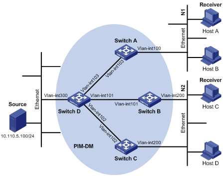
Table 2 shows the interface and IP address assignment, and network topology scheme.
Table 2 Interface and IP address assignment
|
Device |
Interface |
IP address |
|
Switch A |
VLAN-interface 100 |
10.110.1.1/24 |
|
Switch A |
VLAN-interface 103 |
192.168.1.1/24 |
|
Switch B |
VLAN-interface 200 |
10.110.2.1/24 |
|
Switch B |
VLAN-interface 101 |
192.168.2.1/24 |
|
Switch C |
VLAN-interface 200 |
10.110.2.2/24 |
|
Switch C |
VLAN-interface 102 |
192.168.3.1/24 |
|
Switch D |
VLAN-interface 300 |
10.110.5.1/24 |
|
Switch D |
VLAN-interface 103 |
192.168.1.2/24 |
|
Switch D |
VLAN-interface 101 |
192.168.2.2/24 |
|
Switch D |
VLAN-interface 102 |
192.168.3.2/24 |
Configuration procedure
1. Configure the IP address and subnet mask for each interface as per Figure 14. (Details not shown.)
2. Configure OSPF on the switches in the PIM-DM domain to ensure network-layer reachability among them. (Details not shown.)
3. Enable IP multicast routing, and enable PIM-DM and IGMP:
# Enable IP multicast routing on Switch A, enable PIM-DM on each interface, and enable IGMP on VLAN-interface 100, which connects Switch A to the stub network.
<SwitchA> system-view
[SwitchA] multicast routing-enable
[SwitchA] interface vlan-interface 100
[SwitchA-Vlan-interface100] igmp enable
[SwitchA-Vlan-interface100] pim dm
[SwitchA-Vlan-interface100] quit
[SwitchA] interface vlan-interface 103
[SwitchA-Vlan-interface103] pim dm
[SwitchA-Vlan-interface103] quit
# Enable IP multicast routing, PIM-DM, and IGMP on Switch B and Switch C in the same way. (Details not shown.)
# Enable IP multicast routing on Switch D, and enable PIM-DM on each interface.
<SwitchD> system-view
[SwitchD] multicast routing-enable
[SwitchD] interface vlan-interface 300
[SwitchD-Vlan-interface300] pim dm
[SwitchD-Vlan-interface300] quit
[SwitchD] interface vlan-interface 103
[SwitchD-Vlan-interface103] pim dm
[SwitchD-Vlan-interface103] quit
[SwitchD] interface vlan-interface 101
[SwitchD-Vlan-interface101] pim dm
[SwitchD-Vlan-interface101] quit
[SwitchD] interface vlan-interface 102
[SwitchD-Vlan-interface102] pim dm
[SwitchD-Vlan-interface102] quit
Verifying the configuration
# Display the PIM configuration information on Switch D.
[SwitchD] display pim interface
VPN-Instance: public net
Interface NbrCnt HelloInt DR-Pri DR-Address
Vlan300 0 30 1 10.110.5.1 (local)
Vlan103 1 30 1 192.168.1.2 (local)
Vlan101 1 30 1 192.168.2.2 (local)
Vlan102 1 30 1 192.168.3.2 (local)
# Display the PIM neighboring relationships on Switch D.
[SwitchD] display pim neighbor
VPN-Instance: public net
Total Number of Neighbors = 3
Neighbor Interface Uptime Expires Dr-Priority Mode
192.168.1.1 Vlan103 00:02:22 00:01:27 1
192.168.2.1 Vlan101 00:00:22 00:01:29 3
192.168.3.1 Vlan102 00:00:23 00:01:31 5
Assume that Host A needs to receive the information addressed to multicast group G 225.1.1.1. After multicast source S 10.110.5.100/24 sends multicast packets to the multicast group G, an SPT is established through traffic flooding. Switches on the SPT path (Switch A and Switch D) have their (S, G) entries. Host A sends an IGMP report to Switch A to join the multicast group G, and a (*, G) entry is generated on Switch A.
# Display the PIM routing table information on Switch A.
[SwitchA] display pim routing-table
VPN-Instance: public net
Total 1 (*, G) entry; 1 (S, G) entry
(*, 225.1.1.1)
Protocol: pim-dm, Flag: WC
UpTime: 00:04:25
Upstream interface: NULL
Upstream neighbor: NULL
RPF prime neighbor: NULL
Downstream interface(s) information:
Total number of downstreams: 1
1: Vlan-interface100
Protocol: igmp, UpTime: 00:04:25, Expires: never
(10.110.5.100, 225.1.1.1)
Protocol: pim-dm, Flag: ACT
UpTime: 00:06:14
Upstream interface: Vlan-interface103
Upstream neighbor: 192.168.1.2
RPF prime neighbor: 192.168.1.2
Downstream interface(s) information:
Total number of downstreams: 1
1: Vlan-interface100
Protocol: pim-dm, UpTime: 00:04:25, Expires: never
# Display the PIM routing table information on Switch D.
[SwitchD] display pim routing-table
VPN-Instance: public net
Total 0 (*, G) entry; 1 (S, G) entry
(10.110.5.100, 225.1.1.1)
Protocol: pim-dm, Flag: LOC ACT
UpTime: 00:03:27
Upstream interface: Vlan-interface300
Upstream neighbor: NULL
RPF prime neighbor: NULL
Downstream interface(s) information:
Total number of downstreams: 2
1: Vlan-interface103
Protocol: pim-dm, UpTime: 00:03:27, Expires: never
2: Vlan-interface102
Protocol: pim-dm, UpTime: 00:03:27, Expires: never
PIM-SM non-scoped zone configuration example
Network requirements
As shown in Figure 15, receivers receive VOD information through multicast. The receiver groups of different organizations form stub networks, and one or more receiver hosts exist in each stub network. The entire PIM-SM domain contains only one BSR.
Host A and Host C are multicast receivers in two stub networks.
VLAN-interface 105 on Switch D and VLAN-interface 102 on Switch E act as C-BSRs and C-RPs; the C-BSR on Switch E has a higher priority; the multicast group range to which the C-RP is designated is 225.1.1.0/24; modify the hash mask length to map a certain number of consecutive group addresses within the range to the two C-RPs.
IGMPv2 runs between Switch A and N1, and between Switch B/Switch C and N2.

Table 3 shows the interface and IP address assignment, and network topology scheme.
Table 3 Interface and IP address assignment
|
Device |
Interface |
IP address |
|
Switch A |
VLAN-interface 100 |
10.110.1.1/24 |
|
Switch A |
VLAN-interface 101 |
192.168.1.1/24 |
|
Switch A |
VLAN-interface 102 |
192.168.9.1/24 |
|
Switch B |
VLAN-interface 200 |
10.110.2.1/24 |
|
Switch B |
VLAN-interface 103 |
192.168.2.1/24 |
|
Switch C |
VLAN-interface 200 |
10.110.2.2/24 |
|
Switch C |
VLAN-interface 104 |
192.168.3.1/24 |
|
Switch D |
VLAN-interface 300 |
10.110.5.1/24 |
|
Switch D |
VLAN-interface 101 |
192.168.1.2/24 |
|
Switch D |
VLAN-interface 105 |
192.168.4.2/24 |
|
Switch E |
VLAN-interface 104 |
192.168.3.2/24 |
|
Switch E |
VLAN-interface 103 |
192.168.2.2/24 |
|
Switch E |
VLAN-interface 102 |
192.168.9.2/24 |
|
Switch E |
VLAN-interface 105 |
192.168.4.1/24 |
Configuration procedure
1. Configure the IP address and subnet mask for each interface as per Figure 15. (Details not shown.)
2. Configure OSPF on the switches in the PIM-SM domain to ensure network-layer reachability among them. (Details not shown.)
3. Enable IP multicast routing, and enable PIM-SM and IGMP:
# Enable IP multicast routing on Switch A, enable PIM-SM on each interface, and enable IGMP on VLAN-interface 100, which connects Switch A to the stub network.
<SwitchA> system-view
[SwitchA] multicast routing-enable
[SwitchA] interface vlan-interface 100
[SwitchA-Vlan-interface100] igmp enable
[SwitchA-Vlan-interface100] pim sm
[SwitchA-Vlan-interface100] quit
[SwitchA] interface vlan-interface 101
[SwitchA-Vlan-interface101] pim sm
[SwitchA-Vlan-interface101] quit
[SwitchA] interface vlan-interface 102
[SwitchA-Vlan-interface102] pim sm
[SwitchA-Vlan-interface102] quit
# Enable IP multicast routing, PIM-SM, and IGMP on Switch B and Switch C in the same way. (Details not shown.)
# Enable IP multicast routing and PIM-SM on Switch D and Switch E in the same way. (Details not shown.)
4. Configure a C-BSR and a C-RP:
# On Switch D, configure the service scope of RP, specify a C-BSR and a C-RP, and set the hash mask length to 32 and the priority of the C-BSR to 10.
<SwitchD> system-view
[SwitchD] acl number 2005
[SwitchD-acl-basic-2005] rule permit source 225.1.1.0 0.0.0.255
[SwitchD-acl-basic-2005] quit
[SwitchD] pim
[SwitchD-pim] c-bsr vlan-interface 105 32 10
[SwitchD-pim] c-rp vlan-interface 105 group-policy 2005
[SwitchD-pim] quit
# On Switch E, configure the service scope of RP advertisements, specify a C-BSR and a C-RP; and set the hash mask length to 32 and the priority of the C-BSR to 20.
<SwitchE> system-view
[SwitchE] acl number 2005
[SwitchE-acl-basic-2005] rule permit source 225.1.1.0 0.0.0.255
[SwitchE-acl-basic-2005] quit
[SwitchE] pim
[SwitchE-pim] c-bsr vlan-interface 102 32 20
[SwitchE-pim] c-rp vlan-interface 102 group-policy 2005
[SwitchE-pim] quit
Verifying the configuration
# Display the PIM configuration information on Switch A.
[SwitchA] display pim interface
VPN-Instance: public net
Interface NbrCnt HelloInt DR-Pri DR-Address
Vlan100 0 30 1 10.110.1.1 (local)
Vlan101 1 30 1 192.168.1.2
Vlan102 1 30 1 192.168.9.2
# Display the BSR information and the locally configured C-RP information in effect on Switch A.
[SwitchA] display pim bsr-info
VPN-Instance: public net
Elected BSR Address: 192.168.9.2
Priority: 20
Hash mask length: 32
State: Accept Preferred
Scope: Not scoped
Uptime: 00:40:40
Expires: 00:01:42
# Display the BSR information and the locally configured C-RP information in effect on Switch D.
[SwitchD] display pim bsr-info
VPN-Instance: public net
Elected BSR Address: 192.168.9.2
Priority: 20
Hash mask length: 32
State: Accept Preferred
Scope: Not scoped
Uptime: 00:05:26
Expires: 00:01:45
Candidate BSR Address: 192.168.4.2
Priority: 10
Hash mask length: 32
State: Candidate
Scope: Not scoped
Candidate RP: 192.168.4.2(Vlan-interface105)
Priority: 192
HoldTime: 150
Advertisement Interval: 60
Next advertisement scheduled at: 00:00:34
# Display the BSR information and the locally configured C-RP information in effect on Switch E.
[SwitchE] display pim bsr-info
VPN-Instance: public net
Elected BSR Address: 192.168.9.2
Priority: 20
Hash mask length: 32
State: Elected
Scope: Not scoped
Uptime: 00:01:18
Next BSR message scheduled at: 00:01:52
Candidate BSR Address: 192.168.9.2
Priority: 20
Hash mask length: 32
State: Elected
Scope: Not scoped
Candidate RP: 192.168.9.2(Vlan-interface102)
Priority: 192
HoldTime: 150
Advertisement Interval: 60
Next advertisement scheduled at: 00:00:48
# Display the RP information on Switch A.
[SwitchA] display pim rp-info
VPN-Instance: public net
PIM-SM BSR RP information:
Group/MaskLen: 225.1.1.0/24
RP: 192.168.4.2
Priority: 192
HoldTime: 150
Uptime: 00:51:45
Expires: 00:02:22
RP: 192.168.9.2
Priority: 192
HoldTime: 150
Uptime: 00:51:45
Expires: 00:02:22
Assume that Host A needs to receive information addressed to the multicast group G 225.1.1.0. The RP corresponding to the multicast group G is Switch E as a result of hash calculation, so an RPT will be built between Switch A and Switch E. When the multicast source S 10.110.5.100/24 registers with the RP, an SPT will be built between Switch D and Switch E. After receiving multicast data, Switch A immediately switches from the RPT to the SPT. Switches on the RPT path (Switch A and Switch E) have a (*, G) entry, and switches on the SPT path (Switch A and Switch D) have an (S, G) entry.
# Display the PIM routing table information on Switch A.
[SwitchA] display pim routing-table
VPN-Instance: public net
Total 1 (*, G) entry; 1 (S, G) entry
(*, 225.1.1.0)
RP: 192.168.9.2
Protocol: pim-sm, Flag: WC
UpTime: 00:13:46
Upstream interface: Vlan-interface102
Upstream neighbor: 192.168.9.2
RPF prime neighbor: 192.168.9.2
Downstream interface(s) information:
Total number of downstreams: 1
1: Vlan-interface100
Protocol: igmp, UpTime: 00:13:46, Expires: 00:03:06
(10.110.5.100, 225.1.1.0)
RP: 192.168.9.2
Protocol: pim-sm, Flag: SPT ACT
UpTime: 00:00:42
Upstream interface: Vlan-interface101
Upstream neighbor: 192.168.1.2
RPF prime neighbor: 192.168.1.2
Downstream interface(s) information:
Total number of downstreams: 1
1: Vlan-interface100
Protocol: pim-sm, UpTime: 00:00:42, Expires: 00:03:06
# Display the PIM routing table information on Switch D.
[SwitchD] display pim routing-table
VPN-Instance: public net
Total 0 (*, G) entry; 1 (S, G) entry
(10.110.5.100, 225.1.1.0)
RP: 192.168.9.2
Protocol: pim-sm, Flag: SPT LOC ACT
UpTime: 00:00:42
Upstream interface: Vlan-interface300
Upstream neighbor: NULL
RPF prime neighbor: NULL
Downstream interface(s) information:
Total number of downstreams: 1
1: Vlan-interface105
Protocol: pim-sm, UpTime: 00:00:42, Expires: 00:02:26
# Display the PIM routing table information on Switch E.
[SwitchE] display pim routing-table
VPN-Instance: public net
Total 1 (*, G) entry; 0 (S, G) entry
(*, 225.1.1.0)
RP: 192.168.9.2 (local)
Protocol: pim-sm, Flag: WC
UpTime: 00:13:16
Upstream interface: Register
Upstream neighbor: 192.168.4.2
RPF prime neighbor: 192.168.4.2
Downstream interface(s) information:
Total number of downstreams: 1
1: Vlan-interface102
Protocol: pim-sm, UpTime: 00:13:16, Expires: 00:03:22
PIM-SM admin-scoped zone configuration example
Network requirements
As shown in Figure 16, receivers receive VOD information through multicast. The entire PIM-SM domain is divided into admin-scoped zone 1, admin-scoped zone 2, and the global zone. Switch B, Switch C, and Switch D are ZBRs of these three zones, respectively.
Source 1 and Source 2 send different multicast information to multicast group 239.1.1.1. Host A receives the multicast information from only Source 1, and Host B receives the multicast information from only Source 2. Source 3 sends multicast information to multicast group 224.1.1.1. Host C is a multicast receiver for this multicast group.
VLAN-interface 101 of Switch B acts as a C-BSR and a C-RP of admin-scoped zone 1 to provide services for the multicast group range 239.0.0.0/8. VLAN-interface 104 of Switch D acts as a C-BSR and a C-RP of admin-scoped zone 2 to provide services for the multicast group range 239.0.0.0/8. VLAN-interface 109 of Switch F acts as C-BSRs and C-RPs of the global-scoped zone to provide services for all the multicast groups other than those in the 239.0.0.0/8 range.
IGMPv2 runs between Switch A, Switch E, Switch I and their respective receivers.
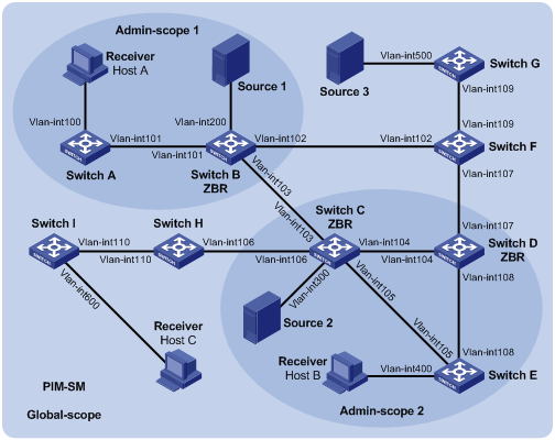
Table 4 shows the interface and IP address assignment, and network topology scheme.
Table 4 Interface and IP address assignment
|
Device |
Interface |
IP address |
Device |
Interface |
IP address |
|
Switch A |
Vlan-int100 |
192.168.1.1/24 |
Switch D |
Vlan-int104 |
10.110.4.2/24 |
|
Switch A |
Vlan-int101 |
10.110.1.1/24 |
Switch D |
Vlan-int108 |
10.110.7.1/24 |
|
Switch B |
Vlan-int200 |
192.168.2.1/24 |
Switch D |
Vlan-int107 |
10.110.8.1/24 |
|
Switch B |
Vlan-int101 |
10.110.1.2/24 |
Switch E |
Vlan-int400 |
192.168.4.1/24 |
|
Switch B |
Vlan-int103 |
10.110.2.1/24 |
Switch E |
Vlan-int105 |
10.110.5.2/24 |
|
Switch B |
Vlan-int102 |
10.110.3.1/24 |
Switch E |
Vlan-int108 |
10.110.7.2/24 |
|
Switch C |
Vlan-int300 |
192.168.3.1/24 |
Switch F |
Vlan-int109 |
10.110.9.1/24 |
|
Switch C |
Vlan-int104 |
10.110.4.1/24 |
Switch F |
Vlan-int107 |
10.110.8.2/24 |
|
Switch C |
Vlan-int105 |
10.110.5.1/24 |
Switch F |
Vlan-int102 |
10.110.3.2/24 |
|
Switch C |
Vlan-int103 |
10.110.2.2/24 |
Switch G |
Vlan-int500 |
192.168.5.1/24 |
|
Switch C |
Vlan-int106 |
10.110.6.1/24 |
Switch G |
Vlan-int109 |
10.110.9.2/24 |
|
Switch H |
Vlan-int110 |
10.110.10.1/24 |
Source 1 |
— |
192.168.2.10/24 |
|
Switch H |
Vlan-int106 |
10.110.6.2/24 |
Source 2 |
— |
192.168.3.10/24 |
|
Switch I |
Vlan-int600 |
192.168.6.1/24 |
Source 3 |
— |
192.168.5.10/24 |
|
Switch I |
Vlan-int110 |
10.110.10.2/24 |
— |
— |
— |
Configuration procedure
1. Configure the IP address and subnet mask for each interface as per Figure 16. (Details not shown.)
2. Configure OSPF on the switches in the PIM-SM domain to ensure network-layer reachability among them. (Details not shown.)
3. Enable IP multicast routing and administrative scoping, and enable PIM-SM and IGMP:
# Enable IP multicast routing and administrative scoping on Switch A, enable PIM-SM on each interface, and enable IGMP on the host-side interface VLAN-interface 100.
<SwitchA> system-view
[SwitchA] multicast routing-enable
[SwitchA] pim
[SwitchA-pim] c-bsr admin-scope
[SwitchA-pim] quit
[SwitchA] interface vlan-interface 100
[SwitchA-Vlan-interface100] igmp enable
[SwitchA-Vlan-interface100] pim sm
[SwitchA-Vlan-interface100] quit
[SwitchA] interface vlan-interface 101
[SwitchA-Vlan-interface101] pim sm
[SwitchA-Vlan-interface101] quit
# Enable IP multicast routing, administrative scoping, PIM-SM, and IGMP on Switch E and Switch I in the same way. (Details not shown.)
# On Switch B, enable IP multicast routing and administrative scoping, and enable PIM-SM on each interface.
<SwitchB> system-view
[SwitchB] multicast routing-enable
[SwitchB] pim
[SwitchB-pim] c-bsr admin-scope
[SwitchB-pim] quit
[SwitchB] interface vlan-interface 200
[SwitchB-Vlan-interface200] pim sm
[SwitchB-Vlan-interface200] quit
[SwitchB] interface vlan-interface 101
[SwitchB-Vlan-interface101] pim sm
[SwitchB-Vlan-interface101] quit
[SwitchB] interface vlan-interface 102
[SwitchB-Vlan-interface102] pim sm
[SwitchB-Vlan-interface102] quit
[SwitchB] interface vlan-interface 103
[SwitchB-Vlan-interface103] pim sm
[SwitchB-Vlan-interface103] quit
# Enable IP multicast routing and administrative scoping, and enable PIM-SM on Switch C, Switch D, Switch F, Switch G, and Switch H in the same way. (Details not shown.)
4. Configure an admin-scoped zone boundary:
# On Switch B, configure VLAN-interface 102 and VLAN-interface 103 to be the boundary of admin-scoped zone 1.
[SwitchB] interface vlan-interface 102
[SwitchB-Vlan-interface102] multicast boundary 239.0.0.0 8
[SwitchB-Vlan-interface102] quit
[SwitchB] interface vlan-interface 103
[SwitchB-Vlan-interface103] multicast boundary 239.0.0.0 8
[SwitchB-Vlan-interface103] quit
# On Switch C, configure VLAN-interface 103 and VLAN-interface 106 to be the boundary of admin-scoped zone 2.
<SwitchC> system-view
[SwitchC] interface vlan-interface 103
[SwitchC-Vlan-interface103] multicast boundary 239.0.0.0 8
[SwitchC-Vlan-interface103] quit
[SwitchC] interface vlan-interface 106
[SwitchC-Vlan-interface106] multicast boundary 239.0.0.0 8
[SwitchC-Vlan-interface106] quit
# On Switch D, configure VLAN-interface 107 to be the boundary of admin-scoped zone 2.
<SwitchD> system-view
[SwitchD] interface vlan-interface 107
[SwitchD-Vlan-interface107] multicast boundary 239.0.0.0 8
[SwitchD-Vlan-interface107] quit
5. Configure C-BSRs and C-RPs:
# On Switch B, configure the service scope of RP advertisements and configure VLAN-interface 101 as a C-BSR and C-RP of admin-scoped zone 1.
[SwitchB] acl number 2001
[SwitchB-acl-basic-2001] rule permit source 239.0.0.0 0.255.255.255
[SwitchB-acl-basic-2001] quit
[SwitchB] pim
[SwitchB-pim] c-bsr group 239.0.0.0 8
[SwitchB-pim] c-bsr vlan-interface 101
[SwitchB-pim] c-rp vlan-interface 101 group-policy 2001
[SwitchB-pim] quit
# On Switch D, configure the service scope of RP advertisements and configure VLAN-interface 104 as a C-BSR and C-RP of admin-scoped zone 2.
[SwitchD] acl number 2001
[SwitchD-acl-basic-2001] rule permit source 239.0.0.0 0.255.255.255
[SwitchD-acl-basic-2001] quit
[SwitchD] pim
[SwitchD-pim] c-bsr group 239.0.0.0 8
[SwitchD-pim] c-bsr vlan-interface 104
[SwitchD-pim] c-rp vlan-interface 104 group-policy 2001
[SwitchD-pim] quit
# On Switch F, configure VLAN-interface 109 as a C-BSR and C-RP in the global-scoped zone.
<SwitchF> system-view
[SwitchF] pim
[SwitchF-pim] c-bsr global
[SwitchF-pim] c-bsr vlan-interface 109
[SwitchF-pim] c-rp vlan-interface 109
[SwitchF-pim] quit
Verifying the configuration
# Display the BSR information and the locally configured C-RP information on Switch B.
[SwitchB] display pim bsr-info
VPN-Instance: public net
Elected BSR Address: 10.110.9.1
Priority: 64
Hash mask length: 30
State: Accept Preferred
Scope: Global
Uptime: 00:01:45
Expires: 00:01:25
Elected BSR Address: 10.110.1.2
Priority: 64
Hash mask length: 30
State: Elected
Scope: 239.0.0.0/8
Uptime: 00:04:54
Next BSR message scheduled at: 00:00:06
Candidate BSR Address: 10.110.1.2
Priority: 64
Hash mask length: 30
State: Elected
Scope: 239.0.0.0/8
Candidate RP: 10.110.1.2(Vlan-interface101)
Priority: 192
HoldTime: 150
Advertisement Interval: 60
Next advertisement scheduled at: 00:00:15
# Display the BSR information and the locally configured C-RP information on Switch D.
[SwitchD] display pim bsr-info
VPN-Instance: public net
Elected BSR Address: 10.110.9.1
Priority: 64
Hash mask length: 30
State: Accept Preferred
Scope: Global
Uptime: 00:01:45
Expires: 00:01:25
Elected BSR Address: 10.110.4.2
Priority: 64
Hash mask length: 30
State: Elected
Scope: 239.0.0.0/8
Uptime: 00:03:48
Next BSR message scheduled at: 00:01:12
Candidate BSR Address: 10.110.4.2
Priority: 64
Hash mask length: 30
State: Elected
Scope: 239.0.0.0/8
Candidate RP: 10.110.4.2(Vlan-interface104)
Priority: 192
HoldTime: 150
Advertisement Interval: 60
Next advertisement scheduled at: 00:00:10
# Display the BSR information and the locally configured C-RP information on Switch F.
[SwitchF] display pim bsr-info
VPN-Instance: public net
Elected BSR Address: 10.110.9.1
Priority: 64
Hash mask length: 30
State: Elected
Scope: Global
Uptime: 00:11:11
Next BSR message scheduled at: 00:00:49
Candidate BSR Address: 10.110.9.1
Priority: 64
Hash mask length: 30
State: Elected
Scope: Global
Candidate RP: 10.110.9.1(Vlan-interface109)
Priority: 192
HoldTime: 150
Advertisement Interval: 60
Next advertisement scheduled at: 00:00:55
# Display the RP information on Switch B.
[SwitchB] display pim rp-info
VPN-Instance: public net
PIM-SM BSR RP information:
Group/MaskLen: 224.0.0.0/4
RP: 10.110.9.1
Priority: 192
HoldTime: 150
Uptime: 00:03:39
Expires: 00:01:51
Group/MaskLen: 239.0.0.0/8
RP: 10.110.1.2 (local)
Priority: 192
HoldTime: 150
Uptime: 00:07:44
Expires: 00:01:51
# Display the RP information on Switch D.
[SwitchD] display pim rp-info
VPN-Instance: public net
PIM-SM BSR RP information:
Group/MaskLen: 224.0.0.0/4
RP: 10.110.9.1
Priority: 192
HoldTime: 150
Uptime: 00:03:42
Expires: 00:01:48
Group/MaskLen: 239.0.0.0/8
RP: 10.110.4.2 (local)
Priority: 192
HoldTime: 150
Uptime: 00:06:54
Expires: 00:02:41
# Display the RP information on Switch F.
[SwitchF] display pim rp-info
VPN-Instance: public net
PIM-SM BSR RP information:
Group/MaskLen: 224.0.0.0/4
RP: 10.110.9.1 (local)
Priority: 192
HoldTime: 150
Uptime: 00:00:32
Expires: 00:01:58
BIDIR-PIM configuration example
Network requirements
In the BIDIR-PIM domain shown in Figure 17. Source 1 and Source 2 send different multicast information to multicast group 225.1.1.1. Host A and Host B receive multicast information from the two sources.
VLAN interface 102 of Switch C acts as a C-BSR, and loopback interface 0 of Switch C acts as a C-RP of the BIDIR-PIM domain.
IGMPv2 runs between Switch B and Host A, and between Switch D and Host B.
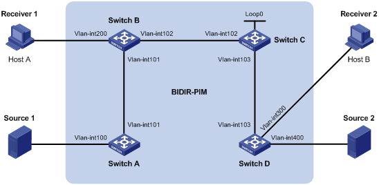
Table 5 shows the interface and IP address assignment, and network topology scheme.
Table 5 Interface and IP address assignment
|
Device |
Interface |
IP address |
|
Switch A |
VLAN-interface 100 |
192.168.1.1/24 |
|
Switch A |
VLAN-interface 101 |
10.110.1.1/24 |
|
Switch B |
VLAN-interface 200 |
192.168.2.1/24 |
|
Switch B |
VLAN-interface 101 |
10.110.1.2/24 |
|
Switch B |
VLAN-interface 102 |
10.110.2.1/24 |
|
Switch C |
VLAN-interface 102 |
10.110.2.2/24 |
|
Switch C |
VLAN-interface 103 |
10.110.3.1/24 |
|
Switch C |
Loopback 0 |
1.1.1.1/32 |
|
Switch D |
VLAN-interface 300 |
192.168.3.1/24 |
|
Switch D |
VLAN-interface 400 |
192.168.4.1/24 |
|
Switch D |
VLAN-interface 103 |
10.110.3.2/24 |
|
Source 1 |
— |
192.168.1.100/24 |
|
Source 2 |
— |
192.168.4.100/24 |
|
Receiver 1 |
— |
192.168.2.100/24 |
|
Receiver 2 |
— |
192.168.3.100/24 |
Configuration procedure
1. Configure an IP address and subnet mask for each interface as per Figure 17. (Details not shown.)
2. Configure OSPF on the switches in the BIDIR-PIM domain to ensure network-layer reachability among them. (Details not shown.)
3. Enable IP multicast routing, PIM-SM, BIDIR-PIM, and IGMP:
# On Switch A, enable IP multicast routing, enable PIM-SM on each interface, and enable BIDIR-PIM.
<SwitchA> system-view
[SwitchA] multicast routing-enable
[SwitchA] interface vlan-interface 100
[SwitchA-Vlan-interface100] pim sm
[SwitchA-Vlan-interface100] quit
[SwitchA] interface vlan-interface 101
[SwitchA-Vlan-interface101] pim sm
[SwitchA-Vlan-interface101] quit
[SwitchA] pim
[SwitchA-pim] bidir-pim enable
[SwitchA-pim] quit
# On Switch B, enable IP multicast routing, enable PIM-SM on each interface, enable IGMP on VLAN interface 200, and enable BIDIR-PIM.
<SwitchB> system-view
[SwitchB] multicast routing-enable
[SwitchB] interface vlan-interface 200
[SwitchB-Vlan-interface200] igmp enable
[SwitchB-Vlan-interface200] pim sm
[SwitchB-Vlan-interface200] quit
[SwitchB] interface vlan-interface 101
[SwitchB-Vlan-interface101] pim sm
[SwitchB-Vlan-interface101] quit
[SwitchB] interface vlan-interface 102
[SwitchB-Vlan-interface102] pim sm
[SwitchB-Vlan-interface102] quit
[SwitchB] pim
[SwitchB-pim] bidir-pim enable
[SwitchB-pim] quit
# On Switch C, enable IP multicast routing, enable PIM-SM on each interface, and enable BIDIR-PIM.
<SwitchC> system-view
[SwitchC] multicast routing-enable
[SwitchC] interface vlan-interface 102
[SwitchC-Vlan-interface102] pim sm
[SwitchC-Vlan-interface102] quit
[SwitchC] interface vlan-interface 103
[SwitchC-Vlan-interface103] pim sm
[SwitchC-Vlan-interface103] quit
[SwitchC] interface loopback 0
[SwitchC-LoopBack0] pim sm
[SwitchC-LoopBack0] quit
[SwitchC] pim
[SwitchC-pim] bidir-pim enable
# On Switch D, enable IP multicast routing, enable PIM-SM on each interface, enable IGMP on VLAN interface 300, and enable BIDIR-PIM.
<SwitchD> system-view
[SwitchD] multicast routing-enable
[SwitchD] interface vlan-interface 300
[SwitchD-Vlan-interface300] igmp enable
[SwitchD-Vlan-interface300] pim sm
[SwitchD-Vlan-interface300] quit
[SwitchD] interface vlan-interface 400
[SwitchD-Vlan-interface400] pim sm
[SwitchD-Vlan-interface400] quit
[SwitchD] interface vlan-interface 103
[SwitchD-Vlan-interface103] pim sm
[SwitchD-Vlan-interface103] quit
[SwitchD] pim
[SwitchD-pim] bidir-pim enable
[SwitchD-pim] quit
4. On Switch C, configure VLAN interface 102 as a C-BSR, and loopback interface 0 as a C-RP for the entire BIDIR-PIM domain.
[SwitchC-pim] c-bsr vlan-interface 102
[SwitchC-pim] c-rp loopback 0 bidir
[SwitchC-pim] quit
Verifying the configuration
# Display the DF information of BIDIR-PIM on Switch A.
[SwitchA] display pim df-info
VPN-Instance: public net
RP Address: 1.1.1.1
Interface State DF-Pref DF-Metric DF-Uptime DF-Address
Vlan100 Win 100 2 01:08:50 192.168.1.1 (local)
Vlan101 Lose 100 1 01:07:49 10.110.1.2
# Display the DF information of BIDIR-PIM on Switch B.
[SwitchB] display pim df-info
VPN-Instance: public net
RP Address: 1.1.1.1
Interface State DF-Pref DF-Metric DF-Uptime DF-Address
Vlan200 Win 100 1 01:24:09 192.168.2.1 (local)
Vlan101 Win 100 1 01:24:09 10.110.1.2 (local)
Vlan102 Lose 0 0 01:23:12 10.110.2.2
# Display the DF information of BIDIR-PIM on Switch C.
[SwitchC] display pim df-info
VPN-Instance: public net
RP Address: 1.1.1.1
Interface State DF-Pref DF-Metric DF-Uptime DF-Address
Loop0 - - - - -
Vlan102 Win 0 0 01:06:07 10.110.2.2 (local)
Vlan103 Win 0 0 01:06:07 10.110.3.1 (local)
# Display the DF information of BIDIR-PIM on Switch D.
[SwitchD] display pim df-info
VPN-Instance: public net
RP Address: 1.1.1.1
Interface State DF-Pref DF-Metric DF-Uptime DF-Address
Vlan300 Win 100 1 01:19:53 192.168.3.1 (local)
Vlan400 Win 100 1 00:39:34 192.168.4.1 (local)
Vlan103 Lose 0 0 01:21:40 10.110.3.1
# Display the DF information of the multicast forwarding table on Switch A.
[SwitchA] display multicast forwarding-table df-info
Multicast DF information of VPN-Instance: public net
Total 1 RP
Total 1 RP matched
00001. RP Address: 1.1.1.1
MID: 0, Flags: 0x2100000:0
Uptime: 00:08:32
RPF interface: Vlan-interface101
List of 1 DF interfaces:
1: Vlan-interface100
# Display the DF information of the multicast forwarding table on Switch B.
[SwitchB] display multicast forwarding-table df-info
Multicast DF information of VPN-Instance: public net
Total 1 RP
Total 1 RP matched
00001. RP Address: 1.1.1.1
MID: 0, Flags: 0x2100000:0
Uptime: 00:06:24
RPF interface: Vlan-interface102
List of 2 DF interfaces:
1: Vlan-interface101
2: Vlan-interface200
# Display the DF information of the multicast forwarding table on Switch C.
[SwitchC] display multicast forwarding-table df-info
Multicast DF information of VPN-Instance: public net
Total 1 RP
Total 1 RP matched
00001. RP Address: 1.1.1.1
MID: 0, Flags: 0x2100000:0
Uptime: 00:07:21
RPF interface: LoopBack0
List of 2 DF interfaces:
1: Vlan-interface102
2: Vlan-interface103
# Display the DF information of the multicast forwarding table on Switch D.
[SwitchD] display multicast forwarding-table df-info
Multicast DF information of VPN-Instance: public net
Total 1 RP
Total 1 RP matched
00001. RP Address: 1.1.1.1
MID: 0, Flags: 0x2100000:0
Uptime: 00:05:12
RPF interface: Vlan-interface103
List of 2 DF interfaces:
1: Vlan-interface300
2: Vlan-interface400
# Display the PIM routing table information on Switch A.
<SwitchA>display pim routing-table
VPN-Instance: public net
Total 2 (*, G) entries; 0 (S, G) entry
(*, 228.0.0.1)
RP: 1.1.1.1
Protocol: pim-sm, Flag: WC BIDIR ACT
UpTime: 16:10:46
Upstream interface: Vlan-interface101
Upstream neighbor: 10.110.1.2
RPF prime neighbor: 10.110.1.2
Downstream interface(s) information:
Total number of downstreams: 2
1: Vlan-interface101
Protocol: pim-sm, UpTime: - , Expires: -
2: Vlan-interface100
Protocol: pim-sm, UpTime: - , Expires: -
(*, 228.0.0.2)
RP: 1.1.1.1
Protocol: pim-sm, Flag: WC BIDIR ACT
UpTime: 16:10:46
Upstream interface: Vlan-interface101
Upstream neighbor: 10.110.1.2
RPF prime neighbor: 10.110.1.2
Downstream interface(s) information:
Total number of downstreams: 2
1: Vlan-interface101
Protocol: pim-sm, UpTime: - , Expires: -
2: Vlan-interface100
Protocol: pim-sm, UpTime: - , Expires: -
The output on Switch B, Switch C, and Switch D is similar to that on Switch A.
PIM-SSM configuration example
Network requirements
As shown in Figure 18, receivers receive VOD information through multicast. The receiver groups of different organizations form stub networks, and one or more receiver hosts exist in each stub network. The entire PIM domain operates in the SSM mode.
Host A and Host C are multicast receivers in two stub networks.
The SSM group range is 232.1.1.0/24.
IGMPv3 runs between Switch A and N1, and between Switch B/Switch C and N2.
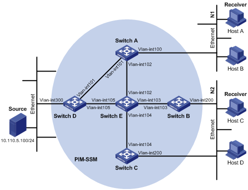
Table 6 shows the interface and IP address assignment, and network topology scheme.
Table 6 Interface and IP address assignment
|
Device |
Interface |
IP address |
|
Switch A |
VLAN-interface 100 |
10.110.1.1/24 |
|
Switch A |
VLAN-interface 101 |
192.168.1.1/24 |
|
Switch A |
VLAN-interface 102 |
192.168.9.1/24 |
|
Switch B |
VLAN-interface 200 |
10.110.2.1/24 |
|
Switch B |
VLAN-interface 103 |
192.168.2.1/24 |
|
Switch C |
VLAN-interface 200 |
10.110.2.2/24 |
|
Switch C |
VLAN-interface 104 |
192.168.3.1/24 |
|
Switch D |
VLAN-interface 300 |
10.110.5.1/24 |
|
Switch D |
VLAN-interface 101 |
192.168.1.2/24 |
|
Switch D |
VLAN-interface 105 |
192.168.4.2/24 |
|
Switch E |
VLAN-interface 104 |
192.168.3.2/24 |
|
Switch E |
VLAN-interface 103 |
192.168.2.2/24 |
|
Switch E |
VLAN-interface 102 |
192.168.9.2/24 |
|
Switch E |
VLAN-interface 105 |
192.168.4.1/24 |
Configuration procedure
1. Configure the IP address and subnet mask for each interface as per Figure 18. (Details not shown.)
2. Configure OSPF on the switches in the PIM-SSM domain to ensure network-layer reachability among them. (Details not shown.)
3. Enable IP multicast routing, and enable PIM-SM and IGMP:
# Enable IP multicast routing on Switch A, enable PIM-SM on each interface, and run IGMPv3 on VLAN-interface 100, which connects Switch A to the stub network.
<SwitchA> system-view
[SwitchA] multicast routing-enable
[SwitchA] interface vlan-interface 100
[SwitchA-Vlan-interface100] igmp enable
[SwitchA-Vlan-interface100] igmp version 3
[SwitchA-Vlan-interface100] pim sm
[SwitchA-Vlan-interface100] quit
[SwitchA] interface vlan-interface 101
[SwitchA-Vlan-interface101] pim sm
[SwitchA-Vlan-interface101] quit
[SwitchA] interface vlan-interface 102
[SwitchA-Vlan-interface102] pim sm
[SwitchA-Vlan-interface102] quit
# Enable IP multicast routing, PIM-SM, and IGMP on Switch B and Switch C in the same way.
# Enable IP multicast routing and PIM-SM on Switch D and Switch E in the same way. (Details not shown.)
4. Configure the SSM group range:
# Configure the SSM group range to be 232.1.1.0/24 one Switch A.
[SwitchA] acl number 2000
[SwitchA-acl-basic-2000] rule permit source 232.1.1.0 0.0.0.255
[SwitchA-acl-basic-2000] quit
[SwitchA] pim
[SwitchA-pim] ssm-policy 2000
[SwitchA-pim] quit
# Configure the SSM group range on Switch B, Switch C, Switch D, and Switch E in the same way. (Details not shown.)
Verifying the configuration
# Display the PIM configuration information on Switch A.
[SwitchA] display pim interface
VPN-Instance: public net
Interface NbrCnt HelloInt DR-Pri DR-Address
Vlan100 0 30 1 10.110.1.1 (local)
Vlan101 1 30 1 192.168.1.2
Vlan102 1 30 1 192.168.9.2
Assume that Host A needs to receive the information a specific multicast source S 10.110.5.100/24 sends to multicast group G 232.1.1.1. Switch A builds an SPT toward the multicast source. Switches on the SPT path (Switch A and Switch D) have generated an (S, G) entry, but Switch E, which is not on the SPT path, does not have multicast routing entries.
# Display the PIM routing table information on Switch A.
[SwitchA] display pim routing-table
VPN-Instance: public net
Total 0 (*, G) entry; 1 (S, G) entry
(10.110.5.100, 232.1.1.1)
Protocol: pim-ssm, Flag:
UpTime: 00:13:25
Upstream interface: Vlan-interface101
Upstream neighbor: 192.168.1.2
RPF prime neighbor: 192.168.1.2
Downstream interface(s) information:
Total number of downstreams: 1
1: Vlan-interface100
Protocol: igmp, UpTime: 00:13:25, Expires: 00:03:25
# Display the PIM routing table information on Switch D.
[SwitchD] display pim routing-table
VPN-Instance: public net
Total 0 (*, G) entry; 1 (S, G) entry
(10.110.5.100, 232.1.1.1)
Protocol: pim-ssm, Flag: LOC
UpTime: 00:12:05
Upstream interface: Vlan-interface300
Upstream neighbor: NULL
RPF prime neighbor: NULL
Downstream interface(s) information:
Total number of downstreams: 1
1: Vlan-interface105
Protocol: pim-ssm, UpTime: 00:12:05, Expires: 00:03:25
Troubleshooting PIM
A multicast distribution tree cannot be built correctly
Symptom
None of the routers in the network (including routers directly connected with multicast sources and receivers) has multicast forwarding entries. That is, a multicast distribution tree cannot be built correctly and clients cannot receive multicast data.
Analysis
· When PIM-DM runs on the entire network, multicast data is flooded from the first hop router connected with the multicast source to the last hop router connected with the clients. When the multicast data is flooded to a router, no matter which router is, it creates (S, G) entries only if it has a route to the multicast source. If the router does not have a route to the multicast source, or if PIM-DM is not enabled on the router's RPF interface to the multicast source, the router cannot create (S, G) entries.
· When PIM-SM runs on the entire network, and when a router will join the SPT, the router creates (S, G) entries only if it has a route to the multicast source. If the router does not have a router to the multicast source, or if PIM-DM is not enabled on the router's RPF interface to the multicast source, the router cannot create (S, G) entries.
· When a multicast router receives a multicast packet, it searches the existing unicast routing table for the optimal route to the RPF check object. The outgoing interface of this route will act as the RPF interface and the next hop will be taken as the RPF neighbor. The RPF interface completely relies on the existing unicast route, and is independent of PIM. The RPF interface must be PIM-enabled, and the RPF neighbor must also be a PIM neighbor. If PIM is not enabled on the router where the RPF interface or the RPF neighbor resides, the establishment of a multicast distribution tree will surely fail, causing abnormal multicast forwarding.
· Because a hello message does not carry the PIM mode information, a router that is running PIM cannot identify what PIM mode its PIM neighbor is running. If different PIM modes are enabled on the RPF interface and on the corresponding interface of the RPF neighbor router, the establishment of a multicast distribution tree will surely fail, causing abnormal multicast forwarding.
· The same PIM mode must run on the entire network. Otherwise, the establishment of a multicast distribution tree will surely fail, causing abnormal multicast forwarding.
Solution
1. Use the display ip routing-table command to verify that a unicast route exists from the receiver host to the multicast source.
2. Use the display pim interface command to view the PIM information on each interface, especially on the RPF interface. If PIM is not enabled on the interface, use the pim dm or pim sm command to enable PIM-DM or PIM-SM.
3. Check that the RPF neighbor is a PIM neighbor. Use the display pim neighbor command to view the PIM neighbor information.
4. Check that PIM and IGMP are enabled on the interfaces directly connecting to the multicast source and to the receivers.
5. Use the display pim interface verbose command to verify that the same PIM mode is enabled on the RPF interface and the corresponding interface of the RPF neighbor router.
6. Check that the same PIM mode is enabled on all the routers in the entire network. Make sure that the same PIM mode is enabled on all the routers: PIM-SM on all routers, or PIM-DM on all routers. In the case of PIM-SM, also check that the BSR and RP configurations are correct.
Multicast data is abnormally terminated on an intermediate router
Symptom
An intermediate router can receive multicast data successfully, but the data cannot reach the last hop router. An interface on the intermediate router receives data but no corresponding (S, G) entry is created in the PIM routing table.
Analysis
· If a multicast forwarding boundary has been configured through the multicast boundary command, any multicast packet will be kept from crossing the boundary, and therefore no routing entry can be created in the PIM routing table.
· In addition, the source-policy command filters received multicast packets. If the multicast data fails to pass the ACL rule defined in this command, PIM cannot create the route entry, either.
Solution
1. Use the display current-configuration command to verify the multicast forwarding boundary settings. Use the multicast boundary command to change the multicast forwarding boundary settings.
2. Use the display current-configuration command to verify the multicast filter configuration. Change the ACL rule defined in the source-policy command so that the source/group address of the multicast data can pass ACL filtering.
RPS cannot join SPT in PIM-SM
Symptom
An RPT cannot be established correctly, or the RPs cannot join the SPT to the multicast source.
Analysis
· As the core of a PIM-SM domain, the RPs provide services for specific multicast groups. Multiple RPs can coexist in a network. Make sure that the RP information on all routers is exactly the same, and a specific group is mapped to the same RP. Otherwise, multicast forwarding will fail.
· If the static RP mechanism is used, the same static RP command must be executed on all the routers in the entire network. Otherwise, multicast forwarding will fail.
Solution
1. Use the display ip routing-table command to verify that a route is available on each router to the RP.
2. Use the display pim rp-info command to verify that the RP information is consistent on all routers.
3. Use the display pim rp-info command to verify that the same static RP address has been configured on all the routers in the entire network.
An RPT cannot be established or a source cannot register in PIM-SM
Symptom
C-RPs cannot unicast advertise messages to the BSR. The BSR does not advertise bootstrap messages containing C-RP information and has no unicast route to any C-RP. An RPT cannot be established correctly, or the DR cannot perform source register with the RP.
Analysis
· The C-RPs periodically send C-RP-Adv messages to the BSR by unicast. If a C-RP has no unicast route to the BSR, the BSR cannot receive C-RP-Adv messages from that C-RP and the bootstrap message of the BSR will not contain the information of that C-RP.
· In addition, if the BSR does not have a unicast router to a C-RP, it will discard the C-RP-Adv messages from that C-RP, and therefore the bootstrap messages of the BSR will not contain the information of that C-RP.
· The RP is the core of a PIM-SM domain. Make sure that the RP information on all routers is exactly the same, a specific group G is mapped to the same RP, and unicast routes are available to the RP.
Solution
1. Use the display ip routing-table command to verify that routes to the RP and the BSR are available on each router, and that a route is available between the RP and the BSR. Make sure that each C-RP has a unicast route to the BSR, the BSR has a unicast route to each C-RP, and all the routers in the entire network have a unicast route to the RP.
2. PIM-SM needs the support of the RP and BSR. Use the display pim bsr-info command to verify that the BSR information is available on each router, and then use the display pim rp-info command to check whether the RP information is correct.
3. Use the display pim neighbor command to verify that normal PIM neighboring relationships have been established among the routers.