- Table of Contents
-
- 07-Layer 3 - IP Routing Configuration Guide
- 00-Preface
- 01-Basic IP Routing Configuration
- 02-Static Routing Configuration
- 03-RIP Configuration
- 04-OSPF Configuration
- 05-IS-IS Configuration
- 06-BGP Configuration
- 07-Policy-Based Routing Configuration
- 08-Guard Route Configuration
- 09-IPv6 Static Routing Configuration
- 10-RIPng Configuration
- 11-OSPFv3 Configuration
- 12-IPv6 IS-IS Configuration
- 13-IPv6 BGP Configuration
- 14-IPv6 Policy-Based Routing Configuration
- 15-Routing Policy Configuration
- 16-Tunnel End Packets Policy Routing Configuration
- Related Documents
-
| Title | Size | Download |
|---|---|---|
| 11-OSPFv3 Configuration | 342.9 KB |
Contents
OSPFv3 configuration task list
Configuring OSPFv3 area parameters
Configuring an OSPFv3 stub area
Configuring an OSPFv3 NSSA area
Configuring an OSPFv3 virtual link
Configuring OSPFv3 network types
Configuring the OSPFv3 network type for an interface
Configuring an NBMA or P2MP neighbor
Configuring OSPFv3 routing information control
Configuring OSPFv3 route summarization
Configuring OSPFv3 inbound route filtering
Configuring an OSPFv3 cost for an interface
Configuring the maximum number of OSPFv3 ECMP routes
Configuring a priority for OSPFv3
Configuring OSPFv3 route redistribution
Tuning and optimizing OSPFv3 networks
Configuring a DR priority for an interface
Ignoring MTU check for DD packets
Disabling interfaces from receiving and sending OSPFv3 packets
Enabling the logging of neighbor state changes
Applying IPsec policies for OSPFv3
Displaying and maintaining OSPFv3
Configuring OSPFv3 DR election
Configuring OSPFv3 route redistribution
Configuring OSPFv3 IPsec policies
Troubleshooting OSPFv3 configuration
No OSPFv3 neighbor relationship established
OSPFv3 overview
Introduction to OSPFv3
Open Shortest Path First version 3 (OSPFv3) supports IPv6 and complies with RFC 5340 (OSPF for IPv6).
OSPFv3 and OSPFv2 have the following similarities:
· A 32-bit router ID and area ID
· Packets, including Hello, DD (Data Description), LSR (Link State Request), LSU (Link State Update), LSAck (Link State Acknowledgment)
· Mechanism for finding neighbors and establishing adjacencies
· Mechanism for LSA flooding and aging
OSPFv3 and OSPFv2 have the following differences:
· OSPFv3 runs on a per-link basis, and OSPFv2 runs on a per-IP-subnet basis.
· OSPFv3 supports multiple instances per link, but OSPFv2 does not.
· OSPFv3 identifies neighbors by router ID, and OSPFv2 by IP address.
OSPFv3 packets
OSPFv3 has the following packet types: hello, DD, LSR, LSU, and LSAck. These packets have the same packet header, which is different from the OSPFv2 packet header. The OSPFv3 packet header is only 16 bytes in length, and has no authentication field, but is added with an Instance ID field to support multi-instance per link.
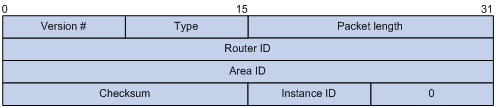
Major fields for OSPFv3 packet header are as follows:
· Version #—Version of OSPF, which is 3 for OSPFv3.
· Type—Type of OSPFv3 packet; Types 1 to 5 are hello, DD, LSR, LSU, and LSAck.
· Packet length—Packet length in bytes, including header.
· Instance ID—Instance ID for a link.
· 0—Reserved. It must be 0.
OSPFv3 LSA types
OSPFv3 sends routing information in LSAs, which, as defined in RFC 5340, have the following types:
· Router-LSA—Originated by all routers. This LSA describes the collected states of the router's interfaces to an area. Flooded throughout a single area only.
· Network-LSA—Originated for broadcast and NBMA networks by the Designated Router. This LSA contains the list of routers connected to the network. Flooded throughout a single area only.
· Inter-Area-Prefix-LSA—Originated by Area Border Routers (ABRs), and flooded throughout the LSA's associated area. Each Inter-Area-Prefix-LSA describes a route with IPv6 address prefix to a destination outside the area, yet still inside the Autonomous System (AS), which is an inter-area route.
· Inter-Area-Router-LSA—Originated by ABRs and flooded throughout the LSA's associated area. Each Inter-Area-Router-LSA describes a route to the Autonomous System Boundary Router (ASBR).
· AS-external-LSA—Originated by ASBRs, and flooded throughout the AS (except Stub and NSSA areas). Each AS-external-LSA describes a route to another AS. A default route can be described by an AS external LSA.
· NSSA-external-LSA—Originated by Not-So-Stubby Area (NSSA) ASBRs and flooded through the NSSA area. Each NSSA-external-LSA describes a route to another AS. A default route outside the AS can be described by an NSSA-external-LSA.
· Link-LSA—A router originates a separate Link-LSA for each attached link. Link-LSAs have link-local flooding scope. Each Link-LSA describes the IPv6 address prefix of the link and Link-local address of the router.
· Intra-Area-Prefix-LSA—Each Intra-Area-Prefix-LSA contains IPv6 prefix information on a router, stub area, or transit area information, and has area flooding scope. It was introduced because Router-LSAs and Network-LSAs contain no address information.
RFC 5187 defines the Grace-LSA. A Grace-LSA is generated by a Graceful Restart (GR) restarter at reboot and transmitted on the local link. The restarter describes the cause and interval of the reboot in the Grace-LSA to tell its neighbors that it performs a GR operation.
OSPFv3 timers
OSPFv3 include the following timers:
· OSPFv3 packet timer
· LSA delay timer
· SPF timer
· GR timer
OSPFv3 packet timer
Hello packets are sent periodically between neighboring routers for finding and maintaining neighbor relationships, or for DR and BDR election. The hello interval must be identical on neighboring interfaces. The smaller the hello interval, the faster the network convergence speed and the bigger the network load.
If a router receives no hello packet from a neighbor within a period, which is called a "dead interval," it will declare the peer is down.
After sending an LSA to its adjacency, a router waits for an acknowledgment from the adjacency. If no response is received after the retransmission interval elapses, the router will send the LSA again. The retransmission interval must be longer than the round-trip time of the LSA.
LSA delay timer
Each LSA has an age in the local link state database (LSDB) (incremented by one per second), but an LSA does not age on transmission. You must add an LSA delay time into the age time before transmission, which is important for low-speed networks.
SPF timer
Whenever the LSDB changes, an SPF calculation happens. If recalculations become frequent, a large amount of resources will be occupied. You can adjust the SPF calculation interval and delay time to protect networks from being overloaded due to frequent changes.
GR timer
If a failure to establish adjacencies occurs during a GR, the switch will be in the GR process for a long time. To avoid such cases, configure the GR timer for the switch to exit the GR process when the timer expires.
OSPFv3 features supported
· Basic features defined in RFC 5340
· OSPFv3 stub area
· OSPFv3 NSSA area
· OSPFv3 multiprocess
· VPN instances
· OSPFv3 GR
· BFD
Protocols and standards
· RFC 2328, OSPF Version 2
· RFC 5187, OSPFv3 Graceful Restart
· RFC 5340, OSPF for IPv6
OSPFv3 configuration task list
|
Task |
Remarks |
|
|
Required. |
||
|
Optional. |
||
|
Optional. |
||
|
Optional. |
||
|
Optional. |
||
|
Optional. |
||
|
Optional. |
||
|
Optional. |
||
|
Optional. |
||
|
Optional. |
||
|
Optional. |
||
|
Optional. |
||
|
Optional. |
||
|
Optional. |
||
|
Optional. |
||
|
Disabling interfaces from receiving and sending OSPFv3 packets |
Optional. |
|
|
Optional. |
||
|
Optional. |
||
|
Optional. |
||
|
Optional. |
||
|
Optional. |
||
Enabling OSPFv3
Configuration prerequisites
Before you enable OSPFv3, complete the following tasks:
· Make neighboring nodes accessible with each other at the network layer.
· Enable IPv6 packet forwarding.
Enabling OSPFv3
To enable an OSPFv3 process on a router, you must enable the OSPFv3 process globally, assign the OSPFv3 process a router ID, and enable the OSPFv3 process on related interfaces.
A router ID uniquely identifies a router within an AS; therefore, you must specify a unique router ID for each OSPFv3 router within the AS to ensure proper operation. If a router runs multiple OSPFv3 processes, specify a unique router ID for each process.
An OSPFv3 process ID has only local significance; therefore, process 1 on a router can exchange packets with process 2 on another router.
To enable OSPFv3:
|
Step |
Command |
Remarks |
|
1. Enter system view. |
system-view |
N/A |
|
2. Enable an OSPFv3 process and enter its view. |
ospfv3 [ process-id ] [ vpn-instance vpn-instance-name ] |
By default, no OSPFv3 process is enabled. For more information about VPN instances, see MPLS Configuration Guide. |
|
3. Specify a router ID. |
router-id router-id |
N/A |
|
4. Enter interface view. |
interface interface-type interface-number |
N/A |
|
5. Enable an OSPFv3 process on the interface. |
ospfv3 process-id area area-id [ instance instance-id ] |
Disabled by default. |
Configuring OSPFv3 area parameters
The stub area, NSSA area, and virtual link features of OSPFv3 are the same as OSPFv2.
Splitting an OSPFv3 AS into multiple areas reduces the number of LSAs and extends OSPFv3 applications. For those non-backbone areas residing on the AS boundary, configure them as stub areas to further reduce the size of routing tables and the number of LSAs.
Non-backbone areas exchange routing information through the backbone area; therefore, the backbone and non-backbone areas, including the backbone itself, must be contiguous. In practice, necessary physical links might not be available for such connectivity. You can configure virtual links to address the problem.
Configuration prerequisites
Before you configure OSPFv3 area parameters, complete the following tasks:
· Enable IPv6 packet forwarding.
· Configure basic OSPFv3.
Configuring an OSPFv3 stub area
Follow these guidelines when you configure an OSPFv3 stub area:
· You cannot remove an OSPFv3 area directly. The area can be removed only when you remove all configurations in area view and all interfaces attached to the area become down.
· All the routers attached to a stub area must be configured with the stub command. The keyword no-summary is only available on the ABR of the stub area.
· If you use the stub command with the keyword no-summary on an ABR, the ABR advertises a default route in an Inter-Area-Prefix-LSA into the stub area. No AS-external-LSA, Inter-Area-Prefix-LSA, or other Inter-Area-Router-LSA is advertised in the area. The stub area of this kind is also known as a totally stub area.
To configure an OSPFv3 stub area:
|
Step |
Command |
Remarks |
|
1. Enter system view. |
system-view |
N/A |
|
2. Enter OSPFv3 view. |
ospfv3 [ process-id ] |
N/A |
|
3. Enter OSPFv3 area view. |
area area-id |
N/A |
|
4. Configure the area as a stub area. |
stub [ no-summary ] |
Not configured by default. |
|
5. Specify a cost for the default route advertised to the stub area. |
default-cost value |
Optional. The default setting is 1. |
Configuring an OSPFv3 NSSA area
|
Step |
Command |
Remarks |
|
1. Enter system view. |
system-view |
N/A |
|
2. Enter OSPFv3 view. |
ospfv3 [ process-id ] |
N/A |
|
3. Enter OSPFv3 area view. |
area area-id |
N/A |
|
4. Configure the area as an NSSA area. |
nssa [ default-route-advertise [ cost cost | type type ] * | no-import-route | no-summary | suppress-fa | { translate-always | translate-never } | translator-stability-interval value ] * |
Not configured by default. |
|
5. Specify a cost for the default route advertised to the NSSA area. |
default-cost value |
Optional. The default setting is 1. |
Configuring an OSPFv3 virtual link
You can configure a virtual link to maintain connectivity between a non-backbone area and the backbone, or in the backbone itself.
|
|
IMPORTANT: · Both ends of a virtual link are ABRs that must be configured with the vlink-peer command. · Do not configure virtual links in the areas of a GR-capable process. |
To configure a virtual link:
|
Step |
Command |
|
1. Enter system view. |
system-view |
|
2. Enter OSPFv3 view. |
ospfv3 [ process-id ] |
|
3. Enter OSPFv3 area view. |
area area-id |
|
4. Configure a virtual link. |
vlink-peer router-id [ hello seconds | retransmit seconds | trans-delay seconds | dead seconds | instance instance-id ] * |
Configuring OSPFv3 network types
OSPFv3 classifies networks into the following types upon the link layer protocol:
By default, the OSPFv3 interface network types vary with the link layer protocols of the interfaces:
· When the link layer protocol is PPP, OSPFv3 considers the network type as P2P by default.
· When the link layer protocol is Ethernet, OSPFv3 considers the network type as broadcast by default.
You can change the network type of an OSPFv3 interface in the following cases:
· An NBMA network must be fully connected. That is, any two routers in the network must be directly reachable to each other through a virtual circuit. If no such direct link is available, you must change the network type through a command.
· If direct connections are not available between some routers in an NBMA network, the type of interfaces associated must be configured as P2MP, or as P2P for interfaces with only one neighbor.
Configuration prerequisites
Before you configure OSPFv3 network types, complete the following tasks:
· Configure IPv6 functions.
· Configure basic OSPFv3.
Configuring the OSPFv3 network type for an interface
|
Step |
Command |
Remarks |
|
1. Enter system view. |
system-view |
N/A |
|
2. Enter interface view. |
interface interface-type interface-number |
N/A |
|
3. Configure a network type for the OSPFv3 interface. |
ospfv3 network-type { broadcast | nbma | p2mp [ non-broadcast ] | p2p } [ instance instance-id ] |
Optional. The network type of an interface depends on the media type of the interface. |
Configuring an NBMA or P2MP neighbor
For NBMA and P2MP interfaces (only when in unicast mode), you must specify the link-local IP addresses of their neighbors because these interfaces cannot find neighbors through broadcasting hello packets. You can also specify DR priorities for neighbors.
To configure an NBMA or P2MP (unicast) neighbor and its DR priority:
|
Step |
Command |
|
1. Enter system view. |
system-view |
|
2. Enter interface view. |
interface interface-type interface-number |
|
3. Specify an NBMA or P2MP (unicast) neighbor and its DR priority. |
ospfv3 peer ipv6-address [ dr-priority dr-priority ] [ instance instance-id ] |
Configuring OSPFv3 routing information control
This section describes how to configure the control of OSPFv3 routing information advertisement and reception, and redistribution from other protocols.
Configuration prerequisites
Before you configure OSPFv3 routing information control, complete the following tasks:
· Enable IPv6 packet forwarding.
· Configure basic OSPFv3.
Configuring OSPFv3 route summarization
If contiguous network segments exist in an area, you can use the abr-summary command to summarize them into one network segment on the ABR. The ABR will advertise only the summary route. Any LSA on the specified network segment will not be advertised, reducing the LSDB size in other areas.
To configure route summarization:
|
Step |
Command |
Remarks |
|
1. Enter system view. |
system-view |
N/A |
|
2. Enter OSPFv3 view. |
ospfv3 [ process-id ] |
N/A |
|
3. Enter OSPFv3 area view. |
area area-id |
N/A |
|
4. Configure a summary route. |
abr-summary ipv6-address prefix-length [ not-advertise ] |
Not configured by default. The abr-summary command takes effect only on ABRs. |
Configuring OSPFv3 inbound route filtering
According to some rules, you can configure OSPFv3 to filter routes that are computed from received LSAs.
To configure OSPFv3 inbound route filtering:
|
Step |
Command |
Remarks |
|
1. Enter system view. |
system-view |
N/A |
|
2. Enter OSPFv3 view. |
ospfv3 [ process-id ] |
N/A |
|
3. Configure inbound route filtering. |
filter-policy { acl-number | ipv6-prefix ipv6-prefix-name } import |
Not configured by default. The filter-policy import command can only filter routes computed by OSPFv3. Only routes not filtered out can be added into the local routing table. |
Configuring an OSPFv3 cost for an interface
You can configure an OSPFv3 cost for an interface with one of the following methods:
· Configure the cost value in interface view.
· Configure a bandwidth reference value for the interface, and OSPFv3 computes the cost automatically based on the bandwidth reference value: Interface OSPFv3 cost = Bandwidth reference value (100 Mbps)/Interface bandwidth (Mbps). If the calculated cost is greater than 65535, the value of 65535 is used; if the calculated cost is smaller than 1, the value of 1 is used.
If the cost value is not configured for an interface, OSPFv3 computes the interface cost value automatically.
To configure an OSPFv3 cost for an interface:
|
Step |
Command |
Remarks |
|
1. Enter system view. |
system-view |
N/A |
|
2. Enter interface view. |
interface interface-type interface-number |
N/A |
|
3. Configure an OSPFv3 cost for the interface. |
ospfv3 cost value [ instance instance-id ] |
Optional. The default cost depends on the interface type: 1 for a VLAN interface; 0 for a loopback interface; computed according to the bandwidth for other interfaces. |
To configure a bandwidth reference value:
|
Step |
Command |
Remarks |
|
1. Enter system view. |
system-view |
N/A |
|
2. Enter OSPFv3 view. |
ospfv3 [ process-id ] |
N/A |
|
3. Configure a bandwidth reference value. |
bandwidth-reference value |
Optional. 100 Mbps by default. |
Configuring the maximum number of OSPFv3 ECMP routes
Perform this task to implement load sharing over ECMP routes.
To configure the maximum number of ECMP routes:
|
Step |
Command |
Remarks |
|
1. Enter system view. |
system-view |
N/A |
|
2. Enter OSPFv3 view. |
ospfv3 [ process-id ] |
N/A |
|
3. Specify the maximum number of ECMP routes. |
maximum load-balancing maximum |
Optional. 16 by default. |
Configuring a priority for OSPFv3
A router can run multiple routing protocols. The system assigns a priority to each protocol. When these routing protocols find the same route, the route found by the protocol with the highest priority is selected.
To configure a priority for OSPFv3:
|
Step |
Command |
Remarks |
|
1. Enter system view. |
system-view |
N/A |
|
2. Enter OSPFv3 view. |
ospfv3 [ process-id ] |
N/A |
|
3. Configure a priority for OSPFv3. |
preference [ ase ] [ route-policy route-policy-name ] preference |
Optional. By default, the priority of OSPFv3 internal routes is 10, and the priority of OSPFv3 external routes is 150. |
Configuring OSPFv3 route redistribution
Follow these guidelines when you configure OSPFv3 route redistribution:
· Executing the import-route or default-route-advertise command on a router makes it become an ASBR.
· You can only inject and advertise a default route by using the default-route-advertise command.
· Because OSPFv3 is a link state routing protocol, it cannot directly filter LSAs to be advertised; you must filter redistributed routes first. Routes that are not filtered out can then be advertised in LSAs.
· The filter-policy export command filters routes redistributed with the import-route command. If the import-route command is not configured, executing the filter-policy export command does not take effect.
To configure OSPFv3 route redistribution:
|
Step |
Command |
Remarks |
|
1. Enter system view. |
system-view |
N/A |
|
2. Enter OSPFv3 view. |
ospfv3 [ process-id ] |
N/A |
|
3. Specify a default cost for redistributed routes. |
default cost value |
Optional. 1 by default. |
|
4. Redistribute routes from another protocol or another OSPFv3 process. |
import-route protocol [ process-id | allow-ibgp ] [ cost value | route-policy route-policy-name | type type ] * |
Not configured by default. |
|
5. Inject a default route. |
default-route-advertise [ always | cost value | type type | route-policy route-policy-name ] * |
Optional. Not injected by default. |
|
6. Filter redistributed routes. |
filter-policy { acl6-number | ipv6-prefix ipv6-prefix-name } export [ isisv6 process-id | ospfv3 process-id | ripng process-id | bgp4+ | direct | static ] |
Optional. Not configured by default. |
Tuning and optimizing OSPFv3 networks
This section describes configurations of OSPFv3 timers, interface DR priority, MTU check ignorance for DD packets, and disabling interfaces from sending OSPFv3 packets.
The following are OSPFv3 timers:
· Packet timer—Specified to adjust topology convergence speed and network load.
· LSA delay timer—Specified especially for low-speed links.
· SPF timer—Specified to protect networks from being over-loaded due to frequent network changes.
For a broadcast network, you can configure DR priorities for interfaces to affect DR and BDR election.
By disabling an interface from sending OSPFv3 packets, you can make other routers on the network obtain no information from the interface.
Configuration prerequisites
Before you tune and optimize OSPFv3 networks, complete the following tasks:
· Enable IPv6 packet forwarding.
· Configure basic OSPFv3.
Configuring OSPFv3 timers
|
Command |
Remarks |
|
|
1. Enter system view. |
system-view |
N/A |
|
2. Enter interface view. |
interface interface-type interface-number |
N/A |
|
3. Configure the hello interval. |
ospfv3 timer hello seconds [ instance instance-id ] |
Optional. By default, the hello interval on P2P, broadcast interfaces is 10 seconds. |
|
4. Specify the poll interval. |
ospfv3 timer poll seconds [ instance instance-id ] |
Optional. By default, the poll interval is 120 seconds. |
|
5. Configure the dead interval. |
ospfv3 timer dead seconds [ instance instance-id ] |
Optional. By default, the dead interval on P2P, broadcast interfaces is 40 seconds. The dead interval set on neighboring interfaces cannot be too short; otherwise, a neighbor is easily considered down. |
|
6. Configure the LSA retransmission interval. |
ospfv3 timer retransmit interval [ instance instance-id ] |
Optional. By default, the LSA retransmission interval is 5 seconds. The LSA retransmission interval cannot be too short; otherwise, unnecessary retransmissions will occur. |
|
7. Configure the LSA transmission delay. |
ospfv3 trans-delay seconds [ instance instance-id ] |
Optional. By default, the LSA transmission delay is 1 second. |
|
8. Return to system view. |
quit |
N/A |
|
9. Enter OSPFv3 view. |
ospfv3 [ process-id ] |
N/A |
|
10. Configure the SPF timers. |
spf timers delay-interval hold-interval |
Optional. By default, delay-interval is 5 seconds, and hold-interval is 10 seconds. Setting both the delay-interval and hold-interval to 0 triggers an SPF calculation at once, improving the network convergence speed. |
Configuring a DR priority for an interface
|
Step |
Command |
Remarks |
|
1. Enter system view. |
system-view |
N/A |
|
2. Enter interface view. |
interface interface-type interface-number |
N/A |
|
3. Configure a DR priority. |
ospfv3 dr-priority priority [ instance instance-id ] |
Optional. 1 by default. The DR priority of an interface determines the interface's qualification in DR election. Interfaces having the priority 0 cannot become a DR or BDR. |
Ignoring MTU check for DD packets
When LSAs are few in DD packets, it is unnecessary to check the MTU in DD packets to improve efficiency.
To ignore MTU check for DD packets:
|
Step |
Command |
Remarks |
|
1. Enter system view. |
system-view |
N/A |
|
2. Enter interface view. |
interface interface-type interface-number |
N/A |
|
3. Ignore MTU check for DD packets. |
ospfv3 mtu-ignore [ instance instance-id ] |
Not ignored by default. |
Disabling interfaces from receiving and sending OSPFv3 packets
Follow these guidelines when you disable interfaces from receiving and sending OSPFv3 packets:
· Multiple OSPFv3 processes can disable the same interface from receiving and sending OSPFv3 packets. Using the silent-interface command disables only the interfaces associated with the current process.
· After an OSPFv3 interface is set to silent, direct routes of the interface can still be advertised in Intra-Area-Prefix-LSAs through other interfaces, but other OSPFv3 packets cannot be advertised. Therefore, no neighboring relationship can be established on the interface. This feature can enhance the adaptability of OSPFv3 networking.
To disable interfaces from receiving and sending OSPFv3 packets:
|
Step |
Command |
Remarks |
|
1. Enter system view. |
system-view |
N/A |
|
2. Enter OSPFv3 view. |
ospfv3 [ process-id ] |
N/A |
|
3. Disable interfaces from receiving and sending OSPFv3 packets. |
silent-interface { interface-type interface-number | all } |
Enabled by default. |
Enabling the logging of neighbor state changes
|
Step |
Command |
Remarks |
|
1. Enter system view. |
system-view |
N/A |
|
2. Enter OSPFv3 view. |
ospfv3 [ process-id ] |
N/A |
|
3. Enable the logging of neighbor state changes. |
log-peer-change |
Enabled by default. |
Configuring OSPFv3 GR
|
|
IMPORTANT: You cannot configure OSPFv3 GR after configuring OSPFv3 virtual links, because they are not supported at the same time. |
Graceful Restart ensures the continuity of packet forwarding when a routing protocol restarts or an active/standby switchover occurs:
· GR restarter—Graceful restarting router. It must be Graceful Restart capable.
· GR helper—The neighbor of the GR restarter. It helps the GR restarter to complete the GR process.
To prevent service interruption after a master/backup switchover, a GR restarter running OSPFv3 must complete the following tasks:
· Keep the GR restarter forwarding entries stable during reboot.
· Establish all adjacencies and obtain complete topology information after reboot.
After the active/standby switchover, the GR restarter sends a Grace-LSA to tell its neighbors that it performs a GR. Upon receiving the Grace-LSA, the neighbors with the GR helper capability enter the helper mode (and are thus called GR helpers). Then, the GR restarter retrieves its adjacencies and LSDB with the help of the GR helpers.
Configuring GR restarter
You can configure the GR restarter capability on a GR restarter.
To configure GR restarter:
|
Step |
Command |
Remarks |
|
1. Enter system view. |
system-view |
N/A |
|
2. Enter OSPFv3 view. |
ospfv3 [ process-id ] |
N/A |
|
3. Enable the GR capability. |
graceful-restart enable |
Disabled by default. |
|
4. Configure the GR interval. |
graceful-restart interval interval-value |
Optional. 120 seconds by default. |
Configuring GR helper
You can configure the GR helper capability on a GR helper.
To configure GR helper:
|
Step |
Command |
Remarks |
|
1. Enter system view. |
system-view |
N/A |
|
2. Enter OSPFv3 view. |
ospfv3 [ process-id ] |
N/A |
|
3. Enable the GR helper capability. |
graceful-restart helper enable |
Optional. Enabled by default. |
|
4. Enable strict LSA checking. |
graceful-restart helper strict-lsa-checking |
Optional. Disabled by default. |
Configuring BFD for OSPFv3
After discovering neighbors by sending hello packets, OSPFv3 notifies BFD of the neighbor addresses, and BFD uses these addresses to establish sessions. Before a BFD session is established, it is in down state. In this state, BFD control packets are sent at an interval of no less than 1 second to reduce BFD control packet traffic. After the BFD session is established, BFD control packets are sent at the negotiated interval, thereby implementing fast fault detection.
To configure BFD for OSPFv3, you need to configure OSPFv3 first.
To configure BFD for OSPFv3:
|
Step |
Command |
Remarks |
|
1. Enter system view. |
system-view |
N/A |
|
2. Enter OSPFv3 view. |
ospfv3 [ process-id ] |
N/A |
|
3. Specify a router ID. |
router-id router-id |
N/A |
|
4. Quit the OSPFv3 view. |
quit |
N/A |
|
5. Enter interface view. |
interface interface-type interface-number |
N/A |
|
6. Enable an OSPFv3 process on the interface. |
ospfv3 process-id area area-id [ instance instance-id ] |
Not enabled by default. |
|
7. Enable BFD on the interface. |
ospfv3 bfd enable [ instance instance-id ] |
Not enabled by default. |
Applying IPsec policies for OSPFv3
To protect routing information and defend attacks, OSPFv3 supports using an IPsec policy to authenticate protocol packets as follows.
Outbound OSPFv3 packets carry the Security Parameter Index (SPI) defined in the corresponding IPsec policy. A switch uses the SPI carried in a received packet to match against the configured IPsec policy. If they match, the switch accepts the packet; otherwise, it discards the packet and thus will not establish a neighbor relationship with the sending switch.
You can configure an IPsec policy for an area, an interface or a virtual link.
· To implement area-based IPsec protection, you need to configure the same IPsec policy on the routers in the target area.
· To implement interface-based IPsec protection, you need to configure the same IPsec policy on the interfaces between two neighboring routers.
· To implement virtual link-based IPsec protection, you need to configure the same IPsec policy on the two routers connected over the virtual link.
If an interface and its area each have an IPsec policy configured, the interface uses its own IPsec policy. If a virtual link and area 0 each have an IPsec policy configured, the virtual link uses its own IPsec policy.
Configuration prerequisites
Before you apply an IPsec policy for OSPFv3, complete following tasks.
· Create an IPsec proposal.
· Create an IPsec policy.
For more information about IPsec policy configuration, see Security Configuration Guide.
Configuration guidelines
An IPsec policy used for OSPFv3 can only be in manual mode. For more information, see Security Configuration Guide.
Configuration procedure
To apply an IPsec policy in an area:
|
Step |
Command |
Remarks |
|
1. Enter system view. |
system-view |
N/A |
|
2. Enter OSPFv3 view. |
ospfv3 [ process-id ] |
N/A |
|
3. Enter OSPFv3 area view. |
area area-id |
N/A |
|
4. Apply an IPsec policy in the area. |
enable ipsec-policy policy-name |
Not configured by default. |
To apply an IPsec policy on an interface:
|
Step |
Command |
Remarks |
|
1. Enter system view. |
system-view |
N/A |
|
2. Enter interface view. |
interface interface-type interface-number |
N/A |
|
3. Apply an IPsec policy on the interface. |
ospfv3 ipsec-policy policy-name [ instance instance-id ] |
Not configured by default. |
To apply an IPsec policy on a virtual link:
|
Step |
Command |
Remarks |
|
1. Enter system view. |
system-view |
N/A |
|
2. Enter OSPFv3 view. |
ospfv3 [ process-id ] |
N/A |
|
3. Enter OSPFv3 area view. |
area area-id |
N/A |
|
4. Apply an IPsec policy on a virtual link. |
vlink-peer router-id [ hello seconds | retransmit seconds | trans-delay seconds | dead seconds | instance instance-id | ipsec-policy policy-name ] * |
Not configured by default. |
Displaying and maintaining OSPFv3
|
Task |
Command |
Remarks |
|
Display OSPFv3 process brief information. |
display ospfv3 [ process-id ] [ | { begin | exclude | include } regular-expression ] |
Available in any view. |
|
Display OSPFv3 interface information. |
display ospfv3 interface [ interface-type interface-number | statistic ] [ | { begin | exclude | include } regular-expression ] |
Available in any view. |
|
Display OSPFv3 LSDB information. |
display ospfv3 [ process-id ] lsdb [ { external | grace | inter-prefix | inter-router | intra-prefix | link | network | nssa | router } [ link-state-id ] [ originate-router router-id ] | total ] [ | { begin | exclude | include } regular-expression ] |
Available in any view. |
|
Display OSPFv3 LSDB statistics. |
display ospfv3 lsdb statistic [ | { begin | exclude | include } regular-expression ] |
Available in any view. |
|
Display OSPFv3 neighbor information. |
display ospfv3 [ process-id ] [ area area-id ] peer [ [ interface-type interface-number ] [ verbose ] | peer-router-id ] [ | { begin | exclude | include } regular-expression ] |
Available in any view. |
|
Display OSPFv3 neighbor statistics. |
display ospfv3 peer statistic [ | { begin | exclude | include } regular-expression ] |
Available in any view. |
|
Display OSPFv3 routing table information. |
display ospfv3 [ process-id ] routing [ ipv6-address prefix-length | ipv6-address/prefix-length | abr-routes | asbr-routes | all | statistics ] [ | { begin | exclude | include } regular-expression ] |
Available in any view. |
|
Display OSPFv3 area topology information. |
display ospfv3 [ process-id ] topology [ area area-id ] [ | { begin | exclude | include } regular-expression ] |
Available in any view. |
|
Display OSPFv3 virtual link information. |
display ospfv3 [ process-id ] vlink [ | { begin | exclude | include } regular-expression ] |
Available in any view. |
|
Display OSPFv3 next hop information. |
display ospfv3 [ process-id ] next-hop [ | { begin | exclude | include } regular-expression ] |
Available in any view. |
|
Display OSPFv3 link state request list information. |
display ospfv3 [ process-id ] request-list [ { external | grace | inter-prefix | inter-router | intra-prefix | link | network | nssa | router } [ link-state-id ] [ originate-router ip-address ] | statistics ] [ | { begin | exclude | include } regular-expression ] |
Available in any view. |
|
Display OSPFv3 link state retransmission list information. |
display ospfv3 [ process-id ] retrans-list [ { external | grace | inter-prefix | inter-router | intra-prefix | link | network | nssa | router } [ link-state-id ] [ originate-router ip-address ] | statistics ] [ | { begin | exclude | include } regular-expression ] |
Available in any view. |
|
Display OSPFv3 statistics. |
display ospfv3 statistics [ | { begin | exclude | include } regular-expression ] |
Available in any view. |
|
Display the GR status of the specified OSPFv3 process. |
display ospfv3 [ process-id ] graceful-restart status [ | { begin | exclude | include } regular-expression ] |
Available in any view. |
OSPFv3 configuration examples
By default, Ethernet, VLAN, and aggregate interfaces are down. Before configuring these interfaces, bring them up by using the undo shutdown command.
Configuring OSPFv3 areas
Network requirements
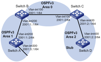
In Figure 2, all switches run OSPFv3. The AS is split into three areas, in which, Switch B and Switch C act as ABRs to forward routing information between areas.
Configure Area 1 as an NSSA area, and configure Area 2 as a stub area to reduce LSAs in the area without affecting route reachability.
Configuration procedure
1. Configure IPv6 addresses for interfaces. (Details not shown.)
2. Configure basic OSPFv3:
# Configure Switch A.
<SwitchA> system-view
[SwitchA] ipv6
[SwitchA] ospfv3
[SwitchA-ospfv3-1] router-id 1.1.1.1
[SwitchA-ospfv3-1] area 1
[SwitchA-ospfv3-1-area-0.0.0.1] nssa
[SwitchA-ospfv3-1] quit
[SwitchA] interface vlan-interface 300
[SwitchA-Vlan-interface300] ospfv3 1 area 1
[SwitchA-Vlan-interface300] quit
[SwitchA] interface vlan-interface 200
[SwitchA-Vlan-interface200] ospfv3 1 area 1
[SwitchA-Vlan-interface200] quit
# Configure Switch B.
<SwitchB> system-view
[SwitchB] ipv6
[SwitchB] ospfv3
[SwitchB-ospfv3-1] router-id 2.2.2.2
[SwitchB-ospfv3-1] area 1
[SwitchB-ospfv3-1-area-0.0.0.1] nssa
[SwitchB-ospfv3-1] quit
[SwitchB] interface vlan-interface 100
[SwitchB-Vlan-interface100] ospfv3 1 area 0
[SwitchB-Vlan-interface100] quit
[SwitchB] interface vlan-interface 200
[SwitchB-Vlan-interface200] ospfv3 1 area 1
[SwitchB-Vlan-interface200] quit
# Configure Switch C.
<SwitchC> system-view
[SwitchC] ipv6
[SwitchC] ospfv3
[SwitchC-ospfv3-1] router-id 3.3.3.3
[SwitchC-ospfv3-1] quit
[SwitchC] interface vlan-interface 100
[SwitchC-Vlan-interface100] ospfv3 1 area 0
[SwitchC-Vlan-interface100] quit
[SwitchC] interface vlan-interface 400
[SwitchC-Vlan-interface400] ospfv3 1 area 2
[SwitchC-Vlan-interface400] quit
# Configure Switch D.
<SwitchD> system-view
[SwitchD] ipv6
[SwitchD] ospfv3
[SwitchD-ospfv3-1] router-id 4.4.4.4
[SwitchD-ospfv3-1] quit
[SwitchD] interface Vlan-interface 400
[SwitchD-Vlan-interface400] ospfv3 1 area 2
[SwitchD-Vlan-interface400] quit
# Display OSPFv3 neighbor information on Switch B.
[SwitchB] display ospfv3 peer
I - Intra area route, E1 - Type 1 external route, N1 – Type 1 NSSA route
IA - Inter area route, E2 – Type 2 external route, N2 – Type 2 NSSA route
* - Selected route
OSPFv3 Area ID 0.0.0.1 (Process 1)
----------------------------------------------------------------------
Neighbor ID Pri State Dead Time Interface Instance ID
1.1.1.1 1 Full/Backup 00:00:38 Vlan200 0
# Display OSPFv3 neighbor information on Switch C.
[SwitchC] display ospfv3 peer
OSPFv3 Area ID 0.0.0.0 (Process 1)
----------------------------------------------------------------------
Neighbor ID Pri State Dead Time Interface Instance ID
2.2.2.2 1 Full/Backup 00:00:39 Vlan100 0
OSPFv3 Area ID 0.0.0.2 (Process 1)
----------------------------------------------------------------------
Neighbor ID Pri State Dead Time Interface Instance ID
4.4.4.4 1 Full/DR 00:00:38 Vlan400 0
# Display OSPFv3 routing table information on Switch D.
[SwitchD] display ospfv3 routing
I - Intra area route, E1 - Type 1 external route, N1 – Type 1 NSSA route
IA - Inter area route, E2 – Type 2 external route, N2 – Type 2 NSSA route
* - Selected route
OSPFv3 Router with ID (4.4.4.4) (Process 1)
------------------------------------------------------------------------
*Destination: 2001::/64
Type : IA Cost : 2
NextHop : FE80::F40D:0:93D0:1 Interface: Vlan400
*Destination: 2001:1::/64
Type : IA Cost : 3
NextHop : FE80::F40D:0:93D0:1 Interface: Vlan400
*Destination: 2001:2::/64
Type : I Cost : 1
NextHop : directly-connected Interface: Vlan400
*Destination: 2001:3::/64
Type : IA Cost : 4
NextHop : FE80::F40D:0:93D0:1 Interface: Vlan400
3. Configure Area 2 as a stub area:
# Configure Switch D.
[SwitchD] ospfv3
[SwitchD-ospfv3-1] area 2
[SwitchD-ospfv3-1-area-0.0.0.2] stub
# Configure Switch C, and specify the cost of the default route sent to the stub area as 10.
[SwitchC] ospfv3
[SwitchC-ospfv3-1] area 2
[SwitchC-ospfv3-1-area-0.0.0.2] stub
[SwitchC-ospfv3-1-area-0.0.0.2] default-cost 10
# Display OSPFv3 routing table information on Switch D. A default route is added, and its cost is the cost of a direct route plus the configured cost.
[SwitchD] display ospfv3 routing
I - Intra area route, E1 - Type 1 external route, N1 – Type 1 NSSA route
IA - Inter area route, E2 – Type 2 external route, N2 – Type 2 NSSA route
* - Selected route
OSPFv3 Router with ID (4.4.4.4) (Process 1)
------------------------------------------------------------------------
*Destination: ::/0
Type : IA Cost : 11
NextHop : FE80::F40D:0:93D0:1 Interface: Vlan400
*Destination: 2001::/64
Type : IA Cost : 2
NextHop : FE80::F40D:0:93D0:1 Interface: Vlan400
*Destination: 2001:1::/64
Type : IA Cost : 3
NextHop : FE80::F40D:0:93D0:1 Interface: Vlan400
*Destination: 2001:2::/64
Type : I Cost : 1
NextHop : directly-connected Interface: Vlan400
*Destination: 2001:3::/64
Type : IA Cost : 4
NextHop : FE80::F40D:0:93D0:1 Interface: Vlan400
4. Configure Area 2 as a totally stub area:
# Configure Area 2 as a totally stub area on Switch C.
[SwitchC-ospfv3-1-area-0.0.0.2] stub no-summary
# Display OSPFv3 routing table information on Switch D. Route entries are reduced. All non-direct routes are removed, except the default route.
[SwitchD] display ospfv3 routing
E1 - Type 1 external route, IA - Inter area route, I - Intra area route
E2 - Type 2 external route, * - Seleted route
OSPFv3 Router with ID (4.4.4.4) (Process 1)
------------------------------------------------------------------------
*Destination: ::/0
Type : IA Cost : 11
NextHop : FE80::F40D:0:93D0:1 Interface: Vlan400
*Destination: 2001:2::/64
Type : I Cost : 1
NextHop : directly-connected Interface: Vlan400
Configuring OSPFv3 DR election
Network requirements
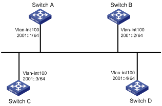
In Figure 3, the priority of Switch A is 100, the highest priority on the network, so it will be the DR. The priority of Switch C is 2, the second highest priority on the network, so it will be the BDR. The priority of Switch B is 0, so it cannot become the DR. Switch D has the default priority 1.
Configuration procedure
1. Configure IPv6 addresses for interfaces. (Details not shown.)
2. Configure basic OSPFv3:
# Configure Switch A.
<SwitchA> system-view
[SwitchA] ipv6
[SwitchA] ospfv3
[SwitchA-ospfv3-1] router-id 1.1.1.1
[SwitchA-ospfv3-1] quit
[SwitchA] interface vlan-interface 100
[SwitchA-Vlan-interface100] ospfv3 1 area 0
[SwitchA-Vlan-interface100] quit
# Configure Switch B.
<SwitchB> system-view
[SwitchB] ipv6
[SwitchB] ospfv3
[SwitchB-ospfv3-1] router-id 2.2.2.2
[SwitchB-ospfv3-1] quit
[SwitchB] interface vlan-interface 100
[SwitchB-Vlan-interface100] ospfv3 1 area 0
[SwitchB-Vlan-interface100] quit
# Configure Switch C.
<SwitchC> system-view
[SwitchC] ipv6
[SwitchC] ospfv3
[SwitchC-ospfv3-1] router-id 3.3.3.3
[SwitchC-ospfv3-1] quit
[SwitchC] interface vlan-interface 100
[SwitchC-Vlan-interface100] ospfv3 1 area 0
[SwitchC-Vlan-interface100] quit
# Configure Switch D.
<SwitchD> system-view
[SwitchD] ipv6
[SwitchD] ospfv3
[SwitchD-ospfv3-1] router-id 4.4.4.4
[SwitchD-ospfv3-1] quit
[SwitchD] interface vlan-interface 100
[SwitchD-Vlan-interface100] ospfv3 1 area 0
[SwitchD-Vlan-interface100] quit
# Display neighbor information on Switch A. The switches have the same default DR priority 1. In this case, the switch with the highest Router ID is elected as the DR; therefore, Switch D is the DR and Switch C is the BDR.
[SwitchA] display ospfv3 peer
OSPFv3 Area ID 0.0.0.0 (Process 1)
----------------------------------------------------------------------
Neighbor ID Pri State Dead Time Interface Instance ID
2.2.2.2 1 2-Way/DROther 00:00:36 Vlan100 0
3.3.3.3 1 Full/Backup 00:00:35 Vlan100 0
4.4.4.4 1 Full/DR 00:00:33 Vlan100 0
# Display neighbor information on Switch D. The neighbor states are all full.
[SwitchD] display ospfv3 peer
OSPFv3 Area ID 0.0.0.0 (Process 1)
----------------------------------------------------------------------
Neighbor ID Pri State Dead Time Interface Instance ID
1.1.1.1 1 Full/DROther 00:00:30 Vlan100 0
2.2.2.2 1 Full/DROther 00:00:37 Vlan100 0
3.3.3.3 1 Full/Backup 00:00:31 Vlan100 0
3. Configure DR priorities for interfaces:
# Configure the DR priority of VLAN-interface 100 as 100 on Switch A.
[SwitchA] interface Vlan-interface 100
[SwitchA-Vlan-interface100] ospfv3 dr-priority 100
[SwitchA-Vlan-interface100] quit
# Configure the DR priority of VLAN-interface 100 as 0 on Switch B.
[SwitchB] interface vlan-interface 100
[SwitchB-Vlan-interface100] ospfv3 dr-priority 0
[SwitchB-Vlan-interface100] quit
# Configure the DR priority of VLAN-interface 100 of Switch C as 2.
[SwitchC] interface Vlan-interface 100
[SwitchC-Vlan-interface100] ospfv3 dr-priority 2
[SwitchC-Vlan-interface100] quit
# Display neighbor information on Switch A. DR priorities have been updated, but the DR and BDR are not changed.
[SwitchA] display ospfv3 peer
OSPFv3 Area ID 0.0.0.0 (Process 1)
----------------------------------------------------------------------
Neighbor ID Pri State Dead Time Interface Instance ID
2.2.2.2 0 2-Way/DROther 00:00:38 Vlan100 0
3.3.3.3 2 Full/Backup 00:00:32 Vlan100 0
4.4.4.4 1 Full/DR 00:00:36 Vlan100 0
# Display neighbor information on Switch D. Switch D is still the DR.
[SwitchD] display ospfv3 peer
OSPFv3 Area ID 0.0.0.0 (Process 1)
----------------------------------------------------------------------
Neighbor ID Pri State Dead Time Interface Instance ID
1.1.1.1 100 Full/DROther 00:00:33 Vlan100 0
2.2.2.2 0 Full/DROther 00:00:36 Vlan100 0
3.3.3.3 2 Full/Backup 00:00:40 Vlan100 0
4. Restart DR and BDR election:
# Use the shutdown and undo shutdown commands on interfaces to restart DR and BDR election. (Details not shown.)
# Display neighbor information on Switch A. Switch C becomes the BDR.
[SwitchA] display ospfv3 peer
OSPFv3 Area ID 0.0.0.0 (Process 1)
----------------------------------------------------------------------
Neighbor ID Pri State Dead Time Interface Instance ID
2.2.2.2 0 Full/DROther 00:00:31 Vlan100 0
3.3.3.3 2 Full/Backup 00:00:39 Vlan100 0
4.4.4.4 1 Full/DROther 00:00:37 Vlan100 0
# Display neighbor information on Switch D. Switch A becomes the DR.
[SwitchD] display ospfv3 peer
OSPFv3 Area ID 0.0.0.0 (Process 1)
----------------------------------------------------------------------
Neighbor ID Pri State Dead Time Interface Instance ID
1.1.1.1 100 Full/DR 00:00:34 Vlan100 0
2.2.2.2 0 2-Way/DROther 00:00:34 Vlan100 0
3.3.3.3 2 Full/Backup 00:00:32 Vlan100 0
Configuring OSPFv3 route redistribution
Network requirements
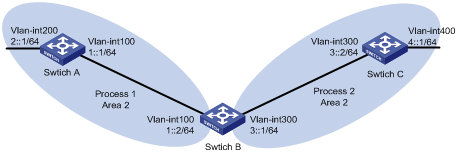
In Figure 4, Switch A, Switch B, and Switch C are in Area 2. OSPFv3 process 1 and OSPFv3 process 2 are enabled on Switch B. Switch B communicates with Switch A and Switch C through OSPFv3 process 1 and OSPFv3 process 2.
Configure OSPFv3 process 2 to redistribute direct routes and the routes from OSPFv3 process 1 on Switch B, and set the default metric for redistributed routes to 3. Switch C can then learn the routes destined for 1::0/64 and 2::0/64, and Switch A cannot learn the routes destined for 3::0/64 or 4::0/64.
Configuration procedure
1. Configure IPv6 addresses for interfaces. (Details not shown.)
2. Configure basic OSPFv3:
# Enable OSPFv3 process 1 on Switch A.
<SwitchA> system-view
[SwitchA] ipv6
[SwitchA] ospfv3 1
[SwitchA-ospfv3-1] router-id 1.1.1.1
[SwitchA-ospfv3-1] quit
[SwitchA] interface vlan-interface 100
[SwitchA-Vlan-interface100] ospfv3 1 area 2
[SwitchA-Vlan-interface100] quit
[SwitchA] interface vlan-interface 200
[SwitchA-Vlan-interface200] ospfv3 1 area 2
[SwitchA-Vlan-interface200] quit
# Enable OSPFv3 process 1 and OSPFv3 process 2 on Switch B.
<SwitchB> system-view
[SwitchB] ipv6
[SwitchB] ospfv3 1
[SwitchB-ospfv3-1] router-id 2.2.2.2
[SwitchB-ospfv3-1] quit
[SwitchB] interface vlan-interface 100
[SwitchB-Vlan-interface100] ospfv3 1 area 2
[SwitchB-Vlan-interface100] quit
[SwitchB] ospfv3 2
[SwitchB-ospfv3-2] router-id 3.3.3.3
[SwitchB-ospfv3-2] quit
[SwitchB] interface vlan-interface 300
[SwitchB-Vlan-interface300] ospfv3 2 area 2
[SwitchB-Vlan-interface300] quit
# Enable OSPFv3 process 2 on Switch C.
<SwitchC> system-view
[SwitchC] ipv6
[SwitchC] ospfv3 2
[SwitchC-ospfv3-2] router-id 4.4.4.4
[SwitchC-ospfv3-2] quit
[SwitchC] interface vlan-interface 300
[SwitchC-Vlan-interface300] ospfv3 2 area 2
[SwitchC-Vlan-interface300] quit
[SwitchC] interface vlan-interface 400
[SwitchC-Vlan-interface400] ospfv3 2 area 2
[SwitchC-Vlan-interface400] quit
# Display the routing table on Switch C.
[SwitchC] display ipv6 routing-table
Routing Table :
Destinations : 6 Routes : 6
Destination: ::1/128 Protocol : Direct
NextHop : ::1 Preference: 0
Interface : InLoop0 Cost : 0
Destination: 3::/64 Protocol : Direct
NextHop : 3::2 Preference: 0
Interface : Vlan300 Cost : 0
Destination: 3::2/128 Protocol : Direct
NextHop : ::1 Preference: 0
Interface : InLoop0 Cost : 0
Destination: 4::/64 Protocol : Direct
NextHop : 4::1 Preference: 0
Interface : Vlan400 Cost : 0
Destination: 4::1/128 Protocol : Direct
NextHop : ::1 Preference: 0
Interface : InLoop0 Cost : 0
Destination: FE80::/10 Protocol : Direct
NextHop : :: Preference: 0
Interface : NULL0 Cost : 0
3. Configure OSPFv3 route redistribution:
# Configure OSPFv3 process 2 to redistribute direct routes and the routes from OSPFv3 process 1 on Switch B.
[SwitchB] ospfv3 2
[SwitchB-ospfv3-2] default cost 3
[SwitchB-ospfv3-2] import-route ospfv3 1
[SwitchB-ospfv3-2] import-route direct
[SwitchB-ospfv3-2] quit
# Display the routing table on Switch C.
[SwitchC] display ipv6 routing-table
Routing Table :
Destinations : 8 Routes : 8
Destination: ::1/128 Protocol : Direct
NextHop : ::1 Preference: 0
Interface : InLoop0 Cost : 0
Destination: 1::/64 Protocol : OSPFv3
NextHop : FE80::200:CFF:FE01:1C03 Preference: 150
Interface : Vlan300 Cost : 3
Destination: 2::/64 Protocol : OSPFv3
NextHop : FE80::200:CFF:FE01:1C03 Preference: 150
Interface : Vlan300 Cost : 3
Destination: 3::/64 Protocol : Direct
NextHop : 3::2 Preference: 0
Interface : Vlan300 Cost : 0
Destination: 3::2/128 Protocol : Direct
NextHop : ::1 Preference: 0
Interface : InLoop0 Cost : 0
Destination: 4::/64 Protocol : Direct
NextHop : 4::1 Preference: 0
Interface : Vlan400 Cost : 0
Destination: 4::1/128 Protocol : Direct
NextHop : ::1 Preference: 0
Interface : InLoop0 Cost : 0
Destination: FE80::/10 Protocol : Direct
NextHop : :: Preference: 0
Interface : NULL0 Cost : 0
Configuring OSPFv3 GR
Network requirements
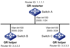
As shown in Figure 5, Switch A, Switch B, and Switch C that belong to the same AS and the same OSPFv3 routing domain are GR capable.
Switch A acts as the GR restarter. Switch B and Switch C are the GR helpers, and synchronize their LSDBs with Switch A through out-of-band (OOB) communication of GR.
Configuration procedure
1. Configure IPv6 addresses for interfaces. (Details not shown.)
2. Configure basic OSPFv3:
# On Switch A, enable OSPFv3 process 1, enable GR, and set the router ID to 1.1.1.1.
<SwitchA> system-view
[SwitchA] ipv6
[SwitchA] ospfv3 1
[SwitchA-ospfv3-1] router-id 1.1.1.1
[SwitchA-ospfv3-1] graceful-restart enable
[SwitchA-ospfv3-1] quit
[SwitchA] interface vlan-interface 100
[SwitchA-Vlan-interface100] ospfv3 1 area 1
[SwitchA-Vlan-interface100] quit
# Enable OSPFv3 on Switch B and set the router ID to 2.2.2.2. (By default, GR helper is enabled on Switch B.)
<SwitchB> system-view
[SwitchB] ipv6
[SwitchB] ospfv3 1
[SwitchB-ospfv3-1] router-id 2.2.2.2
[SwitchB-ospfv3-1] quit
[SwitchB] interface vlan-interface 100
[SwitchB-Vlan-interface100] ospfv3 1 area 1
[SwitchB-Vlan-interface100] quit
# Enable OSPFv3 on Switch C and set the router ID to 3.3.3.3. (By default, GR helper is enabled on Switch C.)
<SwitchC> system-view
[SwitchC] ipv6
[SwitchC] ospfv3 1
[SwitchC-ospfv3-1] router-id 3.3.3.3
[SwitchC-ospfv3-1] quit
[SwitchC] interface vlan-interface 100
[SwitchC-Vlan-interface100] ospfv3 1 area 1
[SwitchC-Vlan-interface100] quit
3. Verify the configuration:
# After all switches function correctly, perform a master/backup switchover on Switch A to trigger an OSPFv3 GR operation.
Configuring BFD for OSPFv3
Network requirements
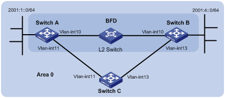
As shown in Figure 6, configure OSPFv3 on Switch A, Switch B and Switch C and configure BFD over the link Switch A<—>L2 Switch<—>Switch B.
After the link Switch A<—>L2 Switch<—>Switch B fails, BFD can quickly detect the failure and notify OSPFv3 of the failure. Then Switch A and Switch B communicate through Switch C.
|
Device |
Interface |
IPv6 address |
Device |
Interface |
IPv6 address |
|
Switch A |
Vlan-int10 |
2001::1/64 |
Switch B |
Vlan-int10 |
2001::2/64 |
|
|
Vlan-int11 |
2001:2::1/64 |
|
Vlan-int13 |
2001:3::2/64 |
|
Switch C |
Vlan-int11 |
2001:2::2/64 |
|
|
|
|
|
Vlan-int13 |
2001:3::1/64 |
|
|
|
Configuration procedure
1. Configure IP addresses for the interfaces. (Details not shown.)
2. Configure basic OSPFv3:
# Configure Switch A, enable OSPFv3, and configure the router ID as 1.1.1.1.
<SwitchA> system-view
[SwitchA] ipv6
[SwitchA] ospfv3
[SwitchA-ospfv3-1] router-id 1.1.1.1
[SwitchA-ospfv3-1] quit
[SwitchA] interface vlan-interface 10
[SwitchA-Vlan-interface10] ospfv3 1 area 0
[SwitchA-Vlan-interface10] quit
[SwitchA] interface vlan-interface 11
[SwitchA-Vlan-interface11] ospfv3 1 area 0
[SwitchA-Vlan-interface11] quit
# Configure Switch B, enable OSPFv3, and configure the router ID as 2.2.2.2.
<SwitchB> system-view
[SwitchB] ipv6
[SwitchB] ospfv3
[SwitchB-ospfv3-1] router-id 2.2.2.2
[SwitchB-ospfv3-1] quit
[SwitchB] interface vlan-interface 10
[SwitchB-Vlan-interface10] ospfv3 1 area 0
[SwitchB-Vlan-interface10] quit
[SwitchB] interface vlan-interface 13
[SwitchB-Vlan-interface13] ospfv3 1 area 0
[SwitchB-Vlan-interface13] quit
# Configure Switch C, enable OSPFv3, and configure the router ID as 3.3.3.3.
<SwitchC> system-view
[SwitchC] ipv6
[SwitchC] ospfv3
[SwitchC-ospfv3-1] router-id 3.3.3.3
[SwitchC-ospfv3-1] quit
[SwitchC] interface vlan-interface 11
[SwitchC-Vlan-interface11] ospfv3 1 area 0
[SwitchC-Vlan-interface11] quit
[SwitchC] interface vlan-interface 13
[SwitchC-Vlan-interface13] ospfv3 1 area 0
[SwitchC-Vlan-interface13] quit
3. Configure BFD:
# Enable BFD on Switch A and configure BFD parameters.
[SwitchA] bfd session init-mode active
[SwitchA] interface vlan-interface 10
[SwitchA-Vlan-interface10] ospfv3 bfd enable
[SwitchA-Vlan-interface10] bfd min-transmit-interval 500
[SwitchA-Vlan-interface10] bfd min-receive-interval 500
[SwitchA-Vlan-interface10] bfd detect-multiplier 7
[SwitchA-Vlan-interface10] return
# Enable BFD on Switch B and configure BFD parameters.
[SwitchB] bfd session init-mode active
[SwitchB] interface vlan-interface 10
[SwitchB-Vlan-interface10] ospfv3 bfd enable
[SwitchB-Vlan-interface10] bfd min-transmit-interval 500
[SwitchB-Vlan-interface10] bfd min-receive-interval 500
[SwitchB-Vlan-interface10] bfd detect-multiplier 6
4. Verify the configuration:
The following operations are performed on Switch A. The operations on Switch B are similar. (Details not shown.)
# Display the BFD information on Switch A.
<SwitchA> display bfd session
Total Session Num: 1 Init Mode: Active
IPv6 Session Working Under Ctrl Mode:
Local Discr: 1441 Remote Discr: 1450
Source IP: FE80::20F:FF:FE00:1202 (link-local address of VLAN-interface 10 on Switch A)
Destination IP: FE80::20F:FF:FE00:1200 (link-local address of VLAN-interface 10 on Switch B)
Session State: Up Interface: Vlan10
Hold Time: /
# Display routes destined for 2001:4::0/64 on Switch A.
<SwitchA> display ipv6 routing-table 2001:4::0 64 verbose
Routing Table :
Summary Count : 2
Destination : 2001:4:: PrefixLength : 64
NextHop : 2001::2 Preference : 10
IpPrecedence : QosLcId :
RelayNextHop : :: Tag : 0H
Neighbor : :: ProcessID : 0
Interface : Vlan-interface10 Protocol : OSPFv3
State : Active Adv Cost : 1
Tunnel ID : 0x0 Label : NULL
Age : 4538sec
Destination : 2001:4:: PrefixLength : 64
NextHop : 2001:2::2 Preference : 10
IpPrecedence : QosLcId :
RelayNextHop : :: Tag : 0H
Neighbor : :: ProcessID : 0
Interface : Vlan-interface11 Protocol : OSPFv3
State : Invalid Adv Cost : 2
Tunnel ID : 0x0 Label : NULL
Age : 4515sec
The output shows that Switch A communicates with Switch B through VLAN-interface 10. Then the link over VLAN-interface 10 fails.
# Enable BFD debugging on Switch A.
<SwitchA> debugging bfd scm
<SwitchA> debugging bfd event
<SwitchA> debugging ospfv3 event bfd
<SwitchA> terminal debugging
%Nov 5 11:37:43:062 2009 SwitchA BFD/5/BFD_CHANGE_FSM: Sess[FE80::20F:FF:FE00:1202/ FE80::20F:FF:FE00:1200,15/15,Vlan10,Ctrl], Sta: UP->DOWN, Diag: 1
%Nov 5 11:37:43:062 2009 SwitchA OSPFV3/5/OSPFv3_NBR_CHG: OSPFv3 1 Neighbor 2.2.2.2(Vlan-interface10) from Full to Down.
*Nov 5 11:37:43:062 2009 SwitchA RM/6/RMDEBUG: OSPFv3 OSPFv3-BFD: Message Type rcv BFD down, Connect Type direct-connect, Src IP Address FE80::20F:FF:FE00:1202, Dst IP Address FE80::20F:FF:FE00:1200.
*Nov 5 11:37:43:062 2009 SwitchA RM/6/RMDEBUG: OSPFv3 OSPFv3-BFD: Message Type delete session, Connect Type direct-connect, Src IP Address FE80::20F:FF:FE00:1202, Dst IP Address FE80::20F:FF:FE00:1200.
The output shows that Switch A can quickly detect the change on Switch B.
# Display the BFD information of Switch A.
<SwitchA> display bfd session
The output shows that Switch A has deleted the BFD session on VLAN-interface 10 to Switch B and displays no output.
# Display routes destined for 2001:4/64 on Switch A.
<SwitchA> display ipv6 routing-table 2001:4::0 64 verbose
Routing Table :
Summary Count : 1
Destination : 2001:4:: PrefixLength : 64
NextHop : 2001:2::2 Preference : 10
IpPrecedence : QosLcId :
RelayNextHop : :: Tag : 0H
Neighbor : :: ProcessID : 0
Interface : Vlan-interface11 Protocol : OSPFv3
State : Active Adv Cost : 2
Tunnel ID : 0x0 Label : NULL
Age : 4610sec
The output shows that Switch A communicates with Switch B through VLAN-interface 11.
Configuring OSPFv3 IPsec policies
Network requirements
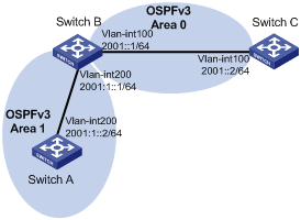
As shown in Figure 7, configure OSPFv3 on the switches. The AS is divided into two areas. Configure IPsec policies on the switches to authenticate and encrypt protocol packets.
Configuration procedure
1. Configure IPv6 addresses for interfaces. (Details not shown.)
2. Configure basic OSPFv3:
# Configure Switch A, enable OSPFv3, and configure the router ID as 1.1.1.1.
<SwitchA> system-view
[SwitchA] ipv6
[SwitchA] ospfv3 1
[SwitchA-ospfv3-1] router-id 1.1.1.1
[SwitchA-ospfv3-1] quit
[SwitchA] interface vlan-interface 200
[SwitchA-Vlan-interface200] ospfv3 1 area 1
[SwitchA-Vlan-interface200] quit
# Configure Switch B, enable OSPFv3, and configure the router ID as 2.2.2.2.
<SwitchB> system-view
[SwitchB] ipv6
[SwitchB] ospfv3 1
[SwitchB-ospfv3-1] router-id 2.2.2.2
[SwitchB-ospfv3-1] quit
[SwitchB] interface vlan-interface 100
[SwitchB-Vlan-interface100] ospfv3 1 area 0
[SwitchB-Vlan-interface100] quit
[SwitchB] interface vlan-interface 200
[SwitchB-Vlan-interface200] ospfv3 1 area 1
[SwitchB-Vlan-interface200] quit
# Configure Switch C, enable OSPFv3, and configure the router ID as 3.3.3.3.
<SwitchC> system-view
[SwitchC] ipv6
[SwitchC] ospfv3 1
[SwitchC-ospfv3-1] router-id 3.3.3.3
[SwitchC-ospfv3-1] quit
[SwitchC] interface vlan-interface 100
[SwitchC-Vlan-interface100] ospfv3 1 area 0
[SwitchC-Vlan-interface100] quit
3. Configure OSPFv3 IPsec policies:
# On Switch A, create an IPsec proposal named tran1, and set the encapsulation mode to transport mode, the security protocol to ESP, the encryption algorithm to DES, and authentication algorithm to SHA1; create an IPsec policy named policy001, specify the manual mode for it, reference IPsec proposal tran1, set the SPIs of the inbound and outbound SAs to 12345, and the keys for the inbound and outbound SAs using ESP to abcdefg.
[SwitchA] ipsec proposal tran1
[SwitchA-ipsec-proposal-tran1] encapsulation-mode transport
[SwitchA-ipsec-proposal-tran1] transform esp
[SwitchA-ipsec-proposal-tran1] esp encryption-algorithm des
[SwitchA-ipsec-proposal-tran1] esp authentication-algorithm sha1
[SwitchA-ipsec-proposal-tran1] quit
[SwitchA] ipsec policy policy001 10 manual
[SwitchA-ipsec-policy-manual-policy001-10] proposal tran1
[SwitchA-ipsec-policy-manual-policy001-10] sa spi outbound esp 12345
[SwitchA-ipsec-policy-manual-policy001-10] sa spi inbound esp 12345
[SwitchA-ipsec-policy-manual-policy001-10] sa string-key outbound esp abcdefg
[SwitchA-ipsec-policy-manual-policy001-10] sa string-key inbound esp abcdefg
[SwitchA-ipsec-policy-manual-policy001-10] quit
# On Switch B, create an IPsec proposal named tran1, and set the encapsulation mode to transport mode, the security protocol to ESP, the encryption algorithm to DES, and authentication algorithm to SHA1; create an IPsec policy named policy001, specify the manual mode for it, reference IPsec proposal tran1, set the SPIs of the inbound and outbound SAs to 12345, and the keys for the inbound and outbound SAs using ESP to abcdefg; create an IPsec proposal named tran2, and set the encapsulation mode to transport mode, the security protocol to ESP, the encryption algorithm to DES, and authentication algorithm to SHA1; create an IPsec policy named policy002, specify the manual mode for it, reference IPsec proposal tran2, set the SPIs of the inbound and outbound SAs to 54321, and the keys for the inbound and outbound SAs using ESP to gfedcba.
[SwitchB] ipsec proposal tran1
[SwitchB-ipsec-proposal-tran1] encapsulation-mode transport
[SwitchB-ipsec-proposal-tran1] transform esp
[SwitchB-ipsec-proposal-tran1] esp encryption-algorithm des
[SwitchB-ipsec-proposal-tran1] esp authentication-algorithm sha1
[SwitchB-ipsec-proposal-tran1] quit
[SwitchB] ipsec policy policy001 10 manual
[SwitchB-ipsec-policy-manual-policy001-10] proposal tran1
[SwitchB-ipsec-policy-manual-policy001-10] sa spi outbound esp 12345
[SwitchB-ipsec-policy-manual-policy001-10] sa spi inbound esp 12345
[SwitchB-ipsec-policy-manual-policy001-10] sa string-key outbound esp abcdefg
[SwitchB-ipsec-policy-manual-policy001-10] sa string-key inbound esp abcdefg
[SwitchB-ipsec-policy-manual-policy001-10] quit
[SwitchB] ipsec proposal tran2
[SwitchB-ipsec-proposal-tran2] encapsulation-mode transport
[SwitchB-ipsec-proposal-tran2] transform esp
[SwitchB-ipsec-proposal-tran2] esp encryption-algorithm des
[SwitchB-ipsec-proposal-tran2] esp authentication-algorithm sha1
[SwitchB-ipsec-proposal-tran2] quit
[SwitchB] ipsec policy policy002 10 manual
[SwitchB-ipsec-policy-manual-policy002-10] proposal tran2
[SwitchB-ipsec-policy-manual-policy002-10] sa spi outbound esp 54321
[SwitchB-ipsec-policy-manual-policy002-10] sa spi inbound esp 54321
[SwitchB-ipsec-policy-manual-policy002-10] sa string-key outbound esp gfedcba
[SwitchB-ipsec-policy-manual-policy002-10] sa string-key inbound esp gfedcba
[SwitchB-ipsec-policy-manual-policy002-10] quit
# On Switch C, create an IPsec proposal named tran2, and set the encapsulation mode to transport mode, the security protocol to ESP, the encryption algorithm to DES, and authentication algorithm to SHA1; create an IPsec policy named policy002, specify the manual mode for it, reference IPsec proposal tran2, set the SPIs of the inbound and outbound SAs to 54321, and the keys for the inbound and outbound SAs using ESP to gfedcba.
[SwitchC] ipsec proposal tran2
[SwitchC-ipsec-proposal-tran2] encapsulation-mode transport
[SwitchC-ipsec-proposal-tran2] transform esp
[SwitchC-ipsec-proposal-tran2] esp encryption-algorithm des
[SwitchC-ipsec-proposal-tran2] esp authentication-algorithm sha1
[SwitchC-ipsec-proposal-tran2] quit
[SwitchC] ipsec policy policy002 10 manual
[SwitchC-ipsec-policy-manual-policy002-10] proposal tran2
[SwitchC-ipsec-policy-manual-policy002-10] sa spi outbound esp 54321
[SwitchC-ipsec-policy-manual-policy002-10] sa spi inbound esp 54321
[SwitchC-ipsec-policy-manual-policy002-10] sa string-key outbound esp gfedcba
[SwitchC-ipsec-policy-manual-policy002-10] sa string-key inbound esp gfedcba
[SwitchC-ipsec-policy-manual-policy002-10] quit
4. Apply the IPsec policies in areas:
# Configure Switch A.
[SwitchA] ospfv3 1
[SwitchA-ospfv3-1] area 1
[SwitchA-ospfv3-1-area-0.0.0.1] enable ipsec-policy policy001
[SwitchA-ospfv3-1-area-0.0.0.1] quit
[SwitchA-ospfv3-1] quit
# Configure Switch B.
[SwitchB] ospfv3 1
[SwitchB-ospfv3-1] area 0
[SwitchB-ospfv3-1-area-0.0.0.0] enable ipsec-policy policy002
[SwitchB-ospfv3-1-area-0.0.0.0] quit
[SwitchB-ospfv3-1] area 1
[SwitchB-ospfv3-1-area-0.0.0.1] enable ipsec-policy policy001
[SwitchB-ospfv3-1-area-0.0.0.1] quit
[SwitchB-ospfv3-1] quit
# Configure Switch C.
[SwitchC] ospfv3 1
[SwitchC-ospfv3-1] area 0
[SwitchC-ospfv3-1-area-0.0.0.0] enable ipsec-policy policy002
[SwitchC-ospfv3-1-area-0.0.0.0] quit
[SwitchC-ospfv3-1] quit
5. Verify the configuration:
OSPFv3 traffic between Switches A, B and C is protected by IPsec.
Troubleshooting OSPFv3 configuration
No OSPFv3 neighbor relationship established
Symptom
No OSPFv3 neighbor relationship can be established.
Analysis
If the physical link and lower protocol work well, check OSPFv3 parameters configured on interfaces. The two neighboring interfaces must have the same parameters, such as the area ID, network segment and mask, and network type. If the network type is broadcast, at least one interface must have a DR priority higher than 0.
Solution
1. Display neighbor information using the display ospfv3 peer command.
2. Display OSPFv3 interface information using the display ospfv3 interface command.
3. Ping the neighbor router's IP address to check connectivity.
4. Check OSPFv3 timers. The dead interval on an interface must be at least four times the hello interval.
5. On a broadcast network, at least one interface must have a DR priority higher than 0.
Incorrect routing information
Symptom
OSPFv3 cannot find routes to other areas.
Analysis
The backbone area must maintain connectivity to all other areas. If a router connects to more than one area, at least one area must be connected to the backbone. The backbone cannot be configured as a stub area.
In a stub area, all routers cannot receive external routes, and interfaces connected to the stub area must be associated with the stub area.
Solution
1. Use the display ospfv3 peer command to display OSPFv3 neighbors.
2. Use the display ospfv3 interface command to display OSPFv3 interface information.
3. Use the display ospfv3 lsdb command to display LSDB information to check integrity.
4. Display information about area configuration using the display current-configuration configuration command. If more than two areas are configured, at least one area is connected to the backbone.
5. In a stub area, all routers are configured with the stub command.
6. If a virtual link is configured, use the display ospfv3 vlink command to check the neighbor state.