- Table of Contents
-
- 07-Layer 3 - IP Routing Configuration Guide
- 00-Preface
- 01-Basic IP Routing Configuration
- 02-Static Routing Configuration
- 03-RIP Configuration
- 04-OSPF Configuration
- 05-IS-IS Configuration
- 06-BGP Configuration
- 07-Policy-Based Routing Configuration
- 08-Guard Route Configuration
- 09-IPv6 Static Routing Configuration
- 10-RIPng Configuration
- 11-OSPFv3 Configuration
- 12-IPv6 IS-IS Configuration
- 13-IPv6 BGP Configuration
- 14-IPv6 Policy-Based Routing Configuration
- 15-Routing Policy Configuration
- 16-Tunnel End Packets Policy Routing Configuration
- Related Documents
-
| Title | Size | Download |
|---|---|---|
| 03-RIP Configuration | 388.18 KB |
Contents
Enabling RIP and a RIP interface
Configuring the interface behavior
Configuring an additional routing metric
Configuring RIPv2 route summarization·
Disabling host route reception
Configuring inbound/outbound route filtering
Configuring a priority for RIP
Configuring RIP route redistribution·
Tuning and optimizing RIP networks
Configuring split horizon and poison reverse
Configuring the maximum number of ECMP routes
Enabling zero field check on incoming RIPv1 messages
Enabling source IP address check on incoming RIP updates
Configuring RIPv2 message authentication
Configuring RIP-to-MIB binding
Configuring the RIP packet sending rate·
Configuring single-hop echo detection
Configuring bidirectional control detection
Displaying and maintaining RIP
Configuring RIP route redistribution·
Configuring an additional metric for a RIP interface
Configuring RIP to advertise a summary route
Configuring BFD for RIP (single-hop echo detection)
Routing Information Protocol (RIP) is a distance-vector simple interior gateway protocol suited to small-sized networks. It employs UDP to exchange route information through port 520.
Overview
RIP uses a hop count to measure the distance to a destination. The hop count from a router to a directly connected network is 0. The hop count from a router to a directly connected router is 1. To limit convergence time, RIP restricts the metric range from 0 to 15. A destination of a metric value of 16 (or greater) is considered unreachable. For this reason, RIP is not suitable for large-sized networks.
RIP prevents routing loops by implementing the split horizon and poison reverse functions.
RIP route entries
RIP stores routing entries in a database. Each routing entry contains the following elements:
· Destination address—IP address of a destination host or a network.
· Next hop—IP address of the next hop.
· Egress interface—Egress interface of the route.
· Metric—Cost from the local router to the destination.
· Route time—Time elapsed since the last update. The time is reset to 0 every time the routing entry is updated.
· Route tag—Used for route control. For more information, see "Configuring routing policies."
RIP timers
RIP employs the following timers:
· Update timer—Specifies the interval between route updates.
· Timeout timer—Specifies the route aging time. If no update for a route is received within the aging time, the metric of the route is set to 16.
· Suppress timer—Specifies the duration a RIP route stays in suppressed state. When the metric of a route is 16, the route enters the suppressed state. A suppressed state can be replaced by an updated route that is received from the same neighbor before the suppress timer expires and has a metric less than 16.
· Garbage-collect timer—Specifies the interval from when the metric of a route becomes 16 to when it is deleted from the routing table. RIP advertises the route with a metric set to 16. If no update is announced for that route before the garbage-collect timer expires, the route is deleted from the routing table.
Routing loops prevention
RIP uses the following mechanisms to prevent routing loops:
· Counting to infinity—A destination with a metric value of 16 is considered unreachable. When a routing loop occurs, the metric value of the route will increment to 16 to avoid endless looping.
· Split horizon—Disables RIP from sending routing information on the interface from which the information was learned to prevent routing loops and save bandwidth.
· Poison reverse—Enables RIP to set the metric of routes received from a neighbor to 16 and sends back these routes to the neighbor so the neighbor can delete such information from its routing table to prevent routing loops.
· Triggered updates—RIP immediately advertises triggered updates for topology changes to reduce the possibility of routing loops and to speed up network convergence.
RIP operation
The following procedure describes how RIP works:
1. After RIP is enabled, the router sends request messages to neighboring routers. Neighboring routers return response messages, including information about their routing tables.
2. After the router receives this information, it updates its local routing table, and sends triggered update messages to its neighbors. All routers on the network do this to keep the latest routing information.
3. RIP ages out routes to keep only valid routes.
RIP versions
RIP has RIPv1 and RIPv2.
RIPv1 is a classful routing protocol, and supports message advertisement through broadcast only. RIPv1 protocol messages do not carry mask information, so it can only recognize routing information of natural networks such as Class A, B, and C. For this reason, RIPv1 does not support discontiguous subnets.
RIPv2 is a classless routing protocol, and has the following advantages over RIPv1:
· Supports route tags, which are used in routing policies to flexibly control routes.
· Supports masks, route summarization, and Classless Inter-Domain Routing (CIDR).
· Supports designated next hops to select the best next hops on broadcast networks.
· Supports multicast routing update to reduce resource consumption. Only RIPv2 routers can receive these update messages.
· Supports plain text authentication and MD5 authentication to enhance security.
|
|
NOTE: RIPv2 has two types of message transmission: broadcast and multicast. Multicast is the default type using 224.0.0.9 as the multicast address. The interface operating in RIPv2 broadcast mode can also receive RIPv1 messages. |
RIP message format
A RIP message consists of a header and up to 25 route entries. (A RIPv2 authentication message uses the first route entry as the authentication entry, leaving 24 available.)
RIPv1 message format
Figure 1 RIPv1 message format
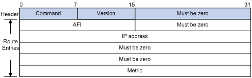
· Command—Type of message. A value of 1 indicates request, which is used to request all or part of the routing information from the neighbor. A value of 2 indicates response, which contains all or part of the routing information. A response message consists of up to 25 route entries.
· Version—Version of RIP. For RIPv1, the value is 0x01.
· Must be zero—This field must be zero.
· AFI—Address Family Identifier. The AFI is 2 for IP.
· IP address—Destination IP address of the route. It can be a natural network, subnet or a host address.
· Metric—Cost of the route.
RIPv2 message format
The format of a RIPv2 message is similar to RIPv1.
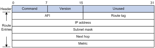
The differences between RIPv1 and RIPv2 messages are stated as follows:
· Version—Version of RIP. For RIPv2, the value is 0x02.
· Route tag—RIPv2 added route tags.
· IP address—In RIPv2, destination IP address can be a natural network address, subnet address, or host address.
· Subnet mask—RIPv2 supports mask of the destination address.
· Next hop—RIPv2 messages include next hop information. If set to 0.0.0.0, it indicates that the originator of the route is the best next hop; otherwise, it indicates a next hop better than the originator of the route.
RIPv2 authentication message format
RIPv2 sets the AFI field of the first route entry to 0xFFFF to identify authentication information.
Figure 3 RIPv2 authentication message
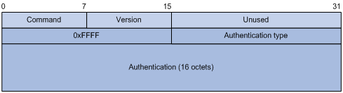
· Authentication type—A value of 2 represents plain text authentication, while a value of 3 represents MD5. RFC 1723 defines only plain text authentication. For MD5 authentication information, see RFC 2453, RIP Version 2.
· Authentication—Authentication data, including password information when plain text authentication is adopted or including key ID, MD5 authentication data length, and sequence number when MD5 authentication is adopted.
|
|
NOTE: Even though with RIPv1, you can configure the authentication mode in interface view, the configuration will not take effect, because RIPv1 does not support authentication. |
Supported RIP features
The current implementation supports the following RIP features:
· RIPv1 and RIPv2
· RIP VPN
RIP can serve as the IGP running between CE and PE on a BGP/MPLS VPN network. For related information, see MPLS Configuration Guide.
· RIP FRR
· BFD
RIP periodically sends route updates to neighbors. If no route update for a route is received within the specified interval, RIP considers the route unreachable. This mechanism cannot detect link faults quickly. After BFD is configured for RIP, when BFD detects a broken link, RIP can quickly age out the unreachable route, thus avoiding interference to other services.
Protocols and standards
· RFC 1058, Routing Information Protocol
· RFC 1723, RIP Version 2 - Carrying Additional Information
· RFC 1721, RIP Version 2 Protocol Analysis
· RFC 1722, RIP Version 2 Protocol Applicability Statement
· RFC 1724, RIP Version 2 MIB Extension
· RFC 2082, RIPv2 MD5 Authentication
· RFC 2091, Triggered Extensions to RIP to Support Demand Circuits
RIP configuration task list
|
Task |
Remarks |
|
|
Required. |
||
|
Optional. |
||
|
Optional. |
||
|
Optional. |
||
|
Optional. |
||
|
Optional. |
||
|
Optional. |
||
|
Optional. |
||
|
Optional. |
||
|
Optional. |
||
|
Optional. |
||
|
Optional. |
||
|
Optional. |
||
|
Optional. |
||
|
Optional. |
||
|
Optional. |
||
|
Optional. |
||
|
Optional. |
||
|
Optional. |
||
|
Optional. |
||
Configuring basic RIP
Configuration prerequisites
Before you configure RIP basic functions, complete the following tasks:
· Configure the link layer protocol.
· Configure IP addresses for interfaces to ensure IP connectivity between neighboring nodes.
Enabling RIP and a RIP interface
Follow these guidelines when you enable RIP:
· RIP configurations made in interface view before enabling RIP take effect after RIP is enabled.
· RIP runs only on the interfaces residing on the specified networks; therefore, you must specify the network after enabling RIP to validate RIP on a specific interface.
· You can enable RIP on all interfaces by using the command network 0.0.0.0.
· If a physical interface is attached to multiple networks, you cannot advertise these networks in different RIP processes.
To enable RIP:
|
Command |
Remarks |
|
|
1. Enter system view. |
system-view |
N/A |
|
2. Enable a RIP process and enter RIP view. |
rip [ process-id ] [ vpn-instance vpn-instance-name ] |
Not enabled by default. |
|
3. Enable RIP on the interface attached to the specified network. |
network network-address |
By default, RIP is disabled on interfaces. |
Configuring the interface behavior
|
Step |
Command |
Remarks |
|
1. Enter system view. |
system-view |
N/A |
|
2. Enter RIP view. |
rip [ process-id ] [ vpn-instance vpn-instance-name ] |
N/A |
|
3. Disable the specific interface or all interfaces from sending routing updates (the interfaces can still receive updates). |
silent-interface { interface-type interface-number | all } |
Optional. By default, all interfaces can send routing updates. |
|
4. Return to system view. |
quit |
N/A |
|
5. Enter interface view. |
interface interface-type interface-number |
N/A |
|
6. Enable the interface to receive RIP messages. |
rip input |
Optional. Enabled by default. |
|
7. Enable the interface to send RIP messages. |
rip output |
Optional. Enabled by default. |
Configuring a RIP version
A RIPv1-enabled interface sends RIPv1 broadcasts, and can receive RIPv1 broadcasts and unicasts.
A RIPv2-enabled multicast interface sends RIPv2 multicasts and can receive RIPv2 unicasts, broadcasts, and multicasts.
A RIPv2-enabled broadcast interface sends RIPv2 broadcasts and can receive RIPv1 unicasts and broadcasts, and RIPv2 broadcasts, multicasts, and unicasts.
You can configure a global RIP version in RIP view or an interface-specific RIP version in interface view.
An interface preferentially uses the interface-specific RIP version. If no interface-specific version is specified, the interface uses the global RIP version. If neither global nor interface-specific RIP version is configured, the interface sends RIPv1 broadcasts, and receives RIPv1 broadcasts and RIPv1 unicasts, and RIPv2 broadcasts, multicasts, and unicasts.
To configure a RIP version:
|
Step |
Command |
Remarks |
|
1. Enter system view. |
system-view |
N/A |
|
2. Enter RIP view. |
rip [ process-id ] [ vpn-instance vpn-instance-name ] |
N/A |
|
3. Specify a global RIP version. |
version { 1 | 2 } |
Optional. By default, if an interface has an interface-specific RIP version, the version takes precedence over the global one. If no interface-specific RIP version is specified, the interface can send RIPv1 broadcasts, and receive RIPv1 broadcasts and unicasts, and RIPv2 broadcasts, multicasts, and unicasts. |
|
4. Return to system view. |
quit |
N/A |
|
5. Enter interface view. |
interface interface-type interface-number |
N/A |
|
6. Specify a RIP version for the interface. |
rip version { 1 | 2 [ broadcast | multicast ] } |
Optional. By default, if an interface has no RIP version specified, the global version takes effect. If no global RIP version is specified, the interface can send RIPv1 broadcasts, and receive RIPv1 broadcasts and unicasts, and RIPv2 broadcasts, multicasts and unicasts. |
Configuring RIP route control
In complex networks, you must configure advanced RIP features.
Before you configure RIP routing feature, complete the following tasks:
· Configure IP addresses for interfaces to ensure IP connectivity between neighboring nodes.
· Configure basic RIP.
Configuring an additional routing metric
An additional routing metric can be added to the metric of an inbound or outbound RIP route.
If the outbound additional metric is added to the metric of a sent route, the route's metric in the routing table is not changed.
The inbound additional metric is added to the metric of a received route before the route is added into the routing table, and the route's metric is changed. If the sum of the additional metric and the original metric is greater than 16, the metric of the route will be 16.
To configure additional routing metrics:
|
Step |
Command |
Remarks |
|
1. Enter system view. |
system-view |
N/A |
|
2. Enter interface view. |
interface interface-type interface-number |
N/A |
|
3. Define an inbound additional routing metric. |
rip metricin [ route-policy route-policy-name ] value |
Optional. 0 by default. |
|
4. Define an outbound additional routing metric. |
rip metricout [ route-policy route-policy-name ] value |
Optional. 1 by default. |
Configuring RIPv2 route summarization
Route summarization means that subnets in a natural network are summarized into a natural network that is sent to other networks. This feature can reduce the size of routing tables.
After route summarization, the smallest metric among all the summarized routes is used as the metric of the summary route.
Enabling RIPv2 route automatic summarization
You can disable RIPv2 route automatic summarization if you want to advertise all subnet routes.
To enable RIPv2 route automatic summarization:
|
Command |
Remarks |
|
|
1. Enter system view. |
system-view |
N/A |
|
2. Enter RIP view. |
rip [ process-id ] [ vpn-instance vpn-instance-name ] |
N/A |
|
3. Enable RIPv2 automatic route summarization. |
summary |
Optional. Enabled by default. If the subnet routes in the routing table are not consecutive, disable automatic route summarization to avoid black hole routing. |
Advertising a summary route
You must disable RIPv2 automatic route summarization before advertising a summary route on an interface.
To configure RIPv2 to advertise a summary route on the specified interface:
|
Step |
Command |
Remarks |
|
1. Enter system view. |
system-view |
N/A |
|
2. Enter RIP view. |
rip [ process-id ] [ vpn-instance vpn-instance-name ] |
N/A |
|
3. Disable RIPv2 automatic route summarization. |
undo summary |
Enabled by default. |
|
4. Return to system view. |
quit |
N/A |
|
5. Enter interface view. |
interface interface-type interface-number |
N/A |
|
6. Advertise a summary route. |
rip summary-address ip-address { mask | mask-length } |
N/A |
Disabling host route reception
Perform this task to disable RIPv2 from receiving host routes from the same network and save network resources. This feature does not apply to RIPv1.
To disable RIP from receiving host routes:
|
Step |
Command |
Remarks |
|
1. Enter system view. |
system-view |
N/A |
|
2. Enter RIP view. |
rip [ process-id ] [ vpn-instance vpn-instance-name ] |
N/A |
|
3. Disable RIP from receiving host routes. |
undo host-route |
By default, RIP receives host routes. |
Advertising a default route
Under the following conditions, you can configure RIP to advertise a default route with a specified metric to RIP neighbors:
· In RIP view, you can configure all the interfaces of the RIP process to advertise a default route. In interface view, you can configure a RIP interface of the RIP process to advertise a default route. The latter takes precedence over the former on the interface.
· If a RIP process is enabled to advertise a default route, to disable an interface of the RIP process from default route advertisement, you can use the rip default-route no-originate command on the interface.
To configure RIP to advertise a default route:
|
Step |
Command |
Remarks |
|
1. Enter system view. |
system-view |
N/A |
|
2. Enter RIP view. |
rip [ process-id ] [ vpn-instance vpn-instance-name ] |
N/A |
|
3. Enable RIP to advertise a default route. |
default-route { only | originate } [ cost cost ] |
Optional. Not enabled by default. |
|
4. Return to system view. |
quit |
N/A |
|
5. Enter interface view. |
interface interface-type interface-number |
N/A |
|
6. Configure the RIP interface to advertise a default route. |
rip default-route { { only | originate } [ cost cost ] | no-originate } |
Optional. By default, a RIP interface can advertise a default route if the RIP process is configured with default route advertisement. |
|
|
NOTE: The router enabled to advertise a default route does not receive default routes from RIP neighbors. |
Configuring inbound/outbound route filtering
The switch supports route filtering. You can filter routes by configuring the inbound and outbound route filtering policies by referencing an ACL or IP prefix list. You can also configure the router to receive routes only from a specified neighbor.
To configure route filtering:
|
Step |
Command |
Remarks |
|
1. Enter system view. |
system-view |
N/A |
|
2. Enter RIP view. |
rip [ process-id ] [ vpn-instance vpn-instance-name ] |
N/A |
|
3. Configure the filtering of incoming routes. |
filter-policy { acl-number | gateway ip-prefix-name | ip-prefix ip-prefix-name [ gateway ip-prefix-name ] } import [ interface-type interface-number ] |
By default, no route filtering policy is configured. The filter-policy import command filters incoming routes. Routes not passing the filtering will be neither installed into the routing table nor advertised to neighbors. |
|
4. Configure the filtering of outgoing routes. |
filter-policy { acl-number | ip-prefix ip-prefix-name } export [ protocol [ process-id ] | interface-type interface-number ] |
By default, no route filtering policy is configured. The filter-policy export command filters outgoing routes, including routes redistributed with the import-route command. |
Configuring a priority for RIP
Multiple IGP protocols can run in a router. If you want RIP routes to have a higher priority than those learned by other routing protocols, assign RIP a smaller priority value to influence optimal route selection.
To configure a priority for RIP:
|
Step |
Command |
Remarks |
|
1. Enter system view. |
system-view |
N/A |
|
2. Enter RIP view. |
rip [ process-id ] [ vpn-instance vpn-instance-name ] |
N/A |
|
3. Configure a priority for RIP. |
preference [ route-policy route-policy-name ] value |
Optional. 100 by default. |
Configuring RIP route redistribution
If a router runs RIP and other routing protocols, you can configure RIP to redistribute OSPF, IS-IS, BGP, static, and direct routes.
Only active routes can be redistributed. You can use the display ip routing-table protocol command to display route state information.
To configure RIP route redistribution:
|
Step |
Command |
Remarks |
|
1. Enter system view. |
system-view |
N/A |
|
2. Enter RIP view. |
rip [ process-id ] [ vpn-instance vpn-instance-name ] |
N/A |
|
3. Configure a default metric for redistributed routes. |
default cost value |
Optional. The default metric of a redistributed route is 0. |
|
4. Redistribute routes from another protocol. |
import-route protocol [ process-id | all-processes | allow-ibgp ] [ cost cost | route-policy route-policy-name | tag tag ] * |
By default, no redistribution is configured. |
Tuning and optimizing RIP networks
Before you tune and optimize RIP networks, complete the following tasks:
· Configure IP addresses for interfaces to ensure IP connectivity between neighboring nodes.
· Configure basic RIP.
Configuring RIP timers
You can change the RIP network convergence speed by adjusting RIP timers. Based on network performance, make RIP timers of RIP routers identical to each other to avoid unnecessary traffic or route oscillation.
To configure RIP timers:
|
Step |
Command |
Remarks |
|
1. Enter system view. |
system-view |
N/A |
|
2. Enter RIP view. |
rip [ process-id ] [ vpn-instance vpn-instance-name ] |
N/A |
|
3. Configure values for RIP timers. |
timers { garbage-collect garbage-collect-value | suppress suppress-value | timeout timeout-value | update update-value } * |
Optional. The default update timer, timeout timer, suppress timer, and garbage-collect timer are 30 seconds, 180 seconds, 120 seconds, and 120 seconds, respectively. |
Configuring split horizon and poison reverse
The split horizon and poison reverse functions can avoid routing loops. If both split horizon and poison reverse are configured, only the poison reverse function takes effect.
Enabling split horizon
The split horizon function disables an interface from sending routing information back on the same interface the information was learned from. This prevents routing loops between adjacent routers. Disabling the split horizon function does not take effect on a point-to-point link.
To enable split horizon:
|
Step |
Command |
Remarks |
|
1. Enter system view. |
system-view |
N/A |
|
2. Enter interface view. |
interface interface-type interface-number |
N/A |
|
3. Enable split horizon. |
rip split-horizon |
Optional. Enabled by default. |
Enabling poison reverse
The poison reverse function allows an interface to advertise the routes back to the sending router. The metric of these routes is always set to 16 (unreachable) to avoid routing loops between neighbors.
To enable poison reverse:
|
Step |
Command |
Remarks |
|
1. Enter system view. |
system-view |
N/A |
|
2. Enter interface view. |
interface interface-type interface-number |
N/A |
|
3. Enable poison reverse. |
rip poison-reverse |
Disabled by default. |
Configuring the maximum number of ECMP routes
Perform this task to implement load sharing over ECMP routes.
To configure the maximum number of ECMP routes:
|
Step |
Command |
Remarks |
|
1. Enter system view. |
system-view |
N/A |
|
2. Enter RIP view. |
rip [ process-id ] [ vpn-instance vpn-instance-name ] |
N/A |
|
3. Configure the maximum number of ECMP routes. |
maximum load-balancing number |
Optional. By default, the maximum number of ECMP routes is 32. |
Enabling zero field check on incoming RIPv1 messages
Some fields in the RIPv1 message must be zero. These fields are called "zero fields." You can enable zero field check on received RIPv1 messages. If a zero field contains a non-zero value, the RIPv1 message is not processed. If you are certain that all messages are trustworthy, disable zero field check to save CPU resources.
This feature does not apply to RIPv2 packets, because they have no zero fields.
To enable zero field check on incoming RIPv1 messages:
|
Step |
Command |
Remarks |
|
1. Enter system view. |
system-view |
N/A |
|
2. Enter RIP view. |
rip [ process-id ] [ vpn-instance vpn-instance-name ] |
N/A |
|
3. Enable zero field check on received RIPv1 messages. |
Checkzero |
Optional. Enabled by default. |
Enabling source IP address check on incoming RIP updates
You can enable source IP address check on incoming RIP updates.
For a message received on an Ethernet interface, RIP compares the source IP address of the message with the IP address of the interface. If they are not in the same network segment, RIP discards the message.
For a message received on a serial interface, RIP checks whether the source address of the message is the IP address of the peer interface. If not, RIP discards the message.
|
|
IMPORTANT: Disable the source IP address check feature if the RIP neighbor is not directly connected. |
To enable source IP address check on incoming RIP updates:
|
Step |
Command |
Remarks |
|
1. Enter system view. |
system-view |
N/A |
|
2. Enter RIP view. |
rip [ process-id ] [ vpn-instance vpn-instance-name ] |
N/A |
|
3. Enable source IP address check on incoming RIP messages. |
validate-source-address |
Optional. Enabled by default. |
Configuring RIPv2 message authentication
In a network requiring high security, you can configure this task to implement RIPv2 message validity check and authentication. This feature does not apply to RIPv1 because RIPv1 does not support authentication. Although you can specify an authentication mode for RIPv1 in interface view, the configuration does not take effect.
RIPv2 supports two authentication modes: plain text and MD5.
In plain text authentication, the authentication information is sent with the RIP message, which however cannot meet high security needs.
To configure RIPv2 message authentication:
|
Step |
Command |
|
1. Enter system view. |
system-view |
|
2. Enter interface view. |
interface interface-type interface-number |
|
3. Configure RIPv2 authentication. |
rip authentication-mode { md5 { rfc2082 [ cipher ] key-string key-id | rfc2453 [ cipher ] key-string } | simple [ cipher ] password } |
Specifying a RIP neighbor
Usually, RIP sends messages to broadcast or multicast addresses. On non-broadcast or multicast links, you must manually specify RIP neighbors.
To specify a RIP neighbor:
|
Step |
Command |
Remarks |
|
1. Enter system view. |
system-view |
N/A |
|
2. Enter RIP view. |
rip [ process-id ] [ vpn-instance vpn-instance-name ] |
N/A |
|
3. Specify a RIP neighbor. |
peer ip-address |
Do not use this command when the neighbor is directly connected. Otherwise, the neighbor might receive both the unicast and multicast (or broadcast) of the same routing information. |
|
4. Disable source address check on incoming RIP updates. |
undo validate-source-address |
Not disabled by default. Disable source address check on incoming updates, if a specified neighbor is not directly connected. |
Configuring RIP-to-MIB binding
This task allows you to enable a specific RIP process to receive SNMP requests.
To bind RIP to MIB:
|
Step |
Command |
Remarks |
|
1. Enter system view. |
system-view |
N/A |
|
2. Bind RIP to MIB. |
rip mib-binding process-id |
Optional. By default, MIB is bound to RIP process 1. |
Configuring the RIP packet sending rate
RIP periodically sends routing information in RIP packets to RIP neighbors. To guarantee device performance and prevent excessive use of bandwidth, specify the maximum number of RIP packets that can be sent at a proper interval.
To configure the RIP packet sending rate:
|
Step |
Command |
Remarks |
|
1. Enter system view. |
system-view |
N/A |
|
2. Enable a RIP process and enter RIP view. |
rip [ process-id ] [ vpn-instance vpn-instance-name ] |
N/A |
|
3. Configure the maximum number of RIP packets that can be sent at the specified interval. |
output-delay time count count |
Optional. By default, an interface sends up to three RIP packets every 20 milliseconds. |
Configuring RIP FRR
When a link in a RIP network fails, the traffic is interrupted until RIP completes routing convergence based on the new network topology.
You can enable RIP fast reroute (FRR) to reduce traffic recovery time.
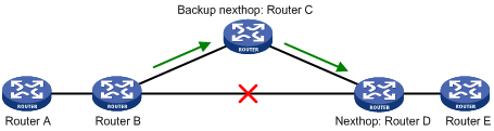
In Figure 4, after you enable FRR on Router B, RIP designates a backup next hop using a routing policy when a network failure is detected. Packets are then directed to the backup next hop for forwarding, reducing traffic recovery time. At the same time, RIP calculates the shortest path based on the new network topology, and forwards packets over that path after network convergence.
Configuration prerequisites
You must specify a next hop by using the apply fast-reroute backup-interface command in a routing policy and reference the routing policy with RIP FRR. For more information about routing policy configuration, see "Configuring routing policies."
Configuration guidelines
· RIP FRR is only effective for non-recursive RIP routes (that are learned from directly connected neighbors).
· Do not use RIP FRR and BFD (for RIP) at the same time. Otherwise, RIP FRR might fail to take effect.
Configuration procedure
To configure RIP FRR:
|
Step |
Command |
Remarks |
|
1. Enter system view. |
system-view |
N/A |
|
2. Configure the source address of echo packets. |
bfd echo-source-ip ip-address |
Not configured by default. |
|
3. Enter RIP view. |
rip [ process-id ] [ vpn-instance vpn-instance-name ] |
N/A |
|
4. Enable RIP FRR and reference a routing policy to designate a backup next hop. |
fast-reroute route-policy route-policy-name |
Disabled by default. |
Configuring BFD for RIP
BFD for RIP provides the following link detection modes:
· Single-hop echo detection mode for a directly connected neighbor. In this mode, a BFD session is established only when the neighbor has route information to send.
· Bidirectional control detection mode for an indirectly connected neighbor. In this mode, a BFD session is established only when both ends have routes to send and BFD is enabled on the receiving interface.
For more information about BFD, see High Availability Configuration Guide.
Configuring single-hop echo detection
|
Step |
Command |
Remarks |
|
1. Enter system view. |
system-view |
N/A |
|
2. Configure the source IP address of BFD echo packets. |
bfd echo-source-ip ip-address |
By default, no source IP address is configured for BFD echo packets. |
|
3. Enter interface view. |
interface interface-type interface-number |
N/A |
|
4. Enable BFD on the RIP interface. |
rip bfd enable |
Disabled by default. |
Configuring bidirectional control detection
This feature only works for RIP neighbors that are directly connected (one hop away from each other).
To configure BFD for RIP (bidirectional control detection):
|
Step |
Command |
Remarks |
|
1. Enter system view. |
system-view |
N/A |
|
2. Create a RIP process and enter RIP view. |
rip [ process-id ] [ vpn-instance vpn-instance-name ] |
By default, RIP is disabled. |
|
3. Specify a RIP neighbor. |
peer ip-address |
By default, RIP does not unicast updates to any peer. |
|
4. Enter interface view. |
interface interface-type interface-number |
N/A |
|
5. Enable BFD on the RIP interface. |
rip bfd enable |
Disabled by default. |
|
|
NOTE: Because the undo peer command does not remove the neighbor relationship at once, executing the command cannot bring down the BFD session at once. |
Displaying and maintaining RIP
|
Command |
Remarks |
|
|
Display RIP current status and configuration information. |
display rip [ process-id | vpn-instance vpn-instance-name ] [ | { begin | exclude | include } regular-expression ] |
Available in any view. |
|
Display all active routes in RIP database. |
display rip process-id database [ | { begin | exclude | include } regular-expression ] |
Available in any view. |
|
Display RIP interface information. |
display rip process-id interface [ interface-type interface-number ] [ | { begin | exclude | include } regular-expression ] |
Available in any view. |
|
Display routing information about a specified RIP process. |
display rip process-id route ip-address { mask | mask-length } | peer ip-address | statistics ] [ | { begin | exclude | include } regular-expression ] |
Available in any view. |
|
Reset a RIP process. |
reset rip process-id process |
Available in user view. |
|
Clear the statistics of a RIP process. |
reset rip process-id statistics |
Available in user view. |
RIP configuration examples
By default, Ethernet, VLAN, and aggregate interfaces are down. Before configuring these interfaces, bring them up by using the undo shutdown command.
Configuring RIP version
Network requirements
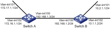
As shown in Figure 5, enable RIPv2 on all interfaces on Switch A and Switch B.
Configuration procedure
1. Configure IP addresses for interfaces. (Details not shown.)
2. Configure basic RIP:
# Configure Switch A.
[SwitchA] rip
[SwitchA-rip-1] network 192.168.1.0
[SwitchA-rip-1] network 172.16.0.0
[SwitchA-rip-1] network 172.17.0.0
# Configure Switch B.
[SwitchB] rip
[SwitchB-rip-1] network 192.168.1.0
[SwitchB-rip-1] network 10.0.0.0
# Display the RIP routing table of Switch A.
[SwitchA] display rip 1 route
Route Flags: R - RIP, T - TRIP
P - Permanent, A - Aging, S - Suppressed, G - Garbage-collect
----------------------------------------------------------------------------
Peer 192.168.1.2 on Vlan-interface100
Destination/Mask Nexthop Cost Tag Flags Sec
10.0.0.0/8 192.168.1.2 1 0 RA 11
The output shows that RIPv1 uses a natural mask.
3. Configure RIP version:
# Configure RIPv2 on Switch A.
[SwitchA] rip
[SwitchA-rip-1] version 2
[SwitchA-rip-1] undo summary
# Configure RIPv2 on Switch B.
[SwitchB] rip
[SwitchB-rip-1] version 2
[SwitchB-rip-1] undo summary
# Display the RIP routing table on Switch A.
[SwitchA] display rip 1 route
Route Flags: R - RIP, T - TRIP
P - Permanent, A - Aging, S - Suppressed, G - Garbage-collect
--------------------------------------------------------------------------
Peer 192.168.1.2 on Vlan-interface100
Destination/Mask Nexthop Cost Tag Flags Sec
10.0.0.0/8 192.168.1.2 1 0 RA 50
10.2.1.0/24 192.168.1.2 1 0 RA 16
10.1.1.0/24 192.168.1.2 1 0 RA 16
The output shows that RIPv2 uses classless subnet mask.
|
|
NOTE: RIPv1 routing information has a long aging time, so it will exist until it ages out after RIPv2 is configured. |
Configuring RIP route redistribution
Network requirements
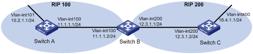
Two RIP processes, as shown in Figure 6, are running on Switch B, which communicates with Switch A through RIP 100 and with Switch C through RIP 200.
Configure route redistribution on Switch B to make RIP 200 redistribute direct routes and routes from RIP 100. Switch C can then learn routes destined for 10.2.1.0/24 and 11.1.1.0/24, while Switch A cannot learn routes destined for 12.3.1.0/24 and 16.4.1.0/24.
Configure a filtering policy on Switch B to filter out route 10.2.1.1/24 from RIP 100, making the route not advertised to Switch C.
Configuration procedure
1. Configure IP addresses for interfaces. (Details not shown.)
2. Configure basic RIP:
# Enable RIP 100 and specify RIPv2 on Switch A.
<SwitchA> system-view
[SwitchA] rip 100
[SwitchA-rip-100] network 10.0.0.0
[SwitchA-rip-100] network 11.0.0.0
[SwitchA-rip-100] version 2
[SwitchA-rip-100] undo summary
[SwitchA-rip-100] quit
# Enable RIP 100 and RIP 200 and specify RIPv2 on Switch B.
<SwitchB> system-view
[SwitchB] rip 100
[SwitchB-rip-100] network 11.0.0.0
[SwitchB-rip-100] version 2
[SwitchB-rip-100] undo summary
[SwitchB-rip-100] quit
[SwitchB] rip 200
[SwitchB-rip-200] network 12.0.0.0
[SwitchB-rip-200] version 2
[SwitchB-rip-200] undo summary
[SwitchB-rip-200] quit
# Enable RIP 200 and specify RIPv2 on Switch C.
<SwitchC> system-view
[SwitchC] rip 200
[SwitchC-rip-200] network 12.0.0.0
[SwitchC-rip-200] network 16.0.0.0
[SwitchC-rip-200] version 2
[SwitchC-rip-200] undo summary
# Display the routing table of Switch C.
[SwitchC] display ip routing-table
Routing Tables: Public
Destinations : 6 Routes : 6
Destination/Mask Proto Pre Cost NextHop Interface
12.3.1.0/24 Direct 0 0 12.3.1.2 Vlan200
12.3.1.2/32 Direct 0 0 127.0.0.1 InLoop0
16.4.1.0/24 Direct 0 0 16.4.1.1 Vlan400
16.4.1.1/32 Direct 0 0 127.0.0.1 InLoop0
127.0.0.0/8 Direct 0 0 127.0.0.1 InLoop0
127.0.0.1/32 Direct 0 0 127.0.0.1 InLoop0
3. Configure route redistribution:
# On Switch B, configure RIP 200 to redistribute direct routes and routes from RIP 100.
[SwitchB] rip 200
[SwitchB-rip-200] import-route rip 100
[SwitchB-rip-200] import-route direct
[SwitchB-rip-200] quit
# Display the IP routing table on Switch C.
[SwitchC] display ip routing-table
Routing Tables: Public
Destinations : 8 Routes : 8
Destination/Mask Proto Pre Cost NextHop Interface
10.2.1.0/24 RIP 100 1 12.3.1.1 Vlan200
11.1.1.0/24 RIP 100 1 12.3.1.1 Vlan200
12.3.1.0/24 Direct 0 0 12.3.1.2 Vlan200
12.3.1.2/32 Direct 0 0 127.0.0.1 InLoop0
16.4.1.0/24 Direct 0 0 16.4.1.1 Vlan400
16.4.1.1/32 Direct 0 0 127.0.0.1 InLoop0
127.0.0.0/8 Direct 0 0 127.0.0.1 InLoop0
127.0.0.1/32 Direct 0 0 127.0.0.1 InLoop0
4. Configure a filtering policy to filter redistributed routes:
# Define ACL 2000 and reference it to a filtering policy to filter routes redistributed from RIP 100 on Switch B, making the route not advertised to Switch C.
[SwitchB] acl number 2000
[SwitchB-acl-basic-2000] rule deny source 10.2.1.1 0.0.0.255
[SwitchB-acl-basic-2000] rule permit
[SwitchB-acl-basic-2000] quit
[SwitchB] rip 200
[SwitchB-rip-200] filter-policy 2000 export rip 100
# Display the IP routing table on Switch C.
[SwitchC] display ip routing-table
Routing Tables: Public
Destinations : 7 Routes : 7
Destination/Mask Proto Pre Cost NextHop Interface
11.1.1.0/24 RIP 100 1 12.3.1.1 Vlan200
12.3.1.0/24 Direct 0 0 12.3.1.2 Vlan200
12.3.1.2/32 Direct 0 0 127.0.0.1 InLoop0
16.4.1.0/24 Direct 0 0 16.4.1.1 Vlan400
16.4.1.1/32 Direct 0 0 127.0.0.1 InLoop0
127.0.0.0/8 Direct 0 0 127.0.0.1 InLoop0
127.0.0.1/32 Direct 0 0 127.0.0.1 InLoop0
Configuring an additional metric for a RIP interface
Network requirements
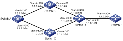
RIP is enabled on all the interfaces of Switch A, Switch B, Switch C, Switch D, and Switch E, as shown in Figure 7. The switches are interconnected through RIPv2.
Switch A has two links to Switch D. The link from Switch B to Switch D is more stable than that from Switch C to Switch D. Configure an additional metric for RIP routes received through VLAN-interface 200 on Switch A so Switch A prefers the 1.1.5.0/24 network learned from Switch B.
Configuration procedure
1. Configure IP addresses for interfaces. (Details not shown.)
2. Configure basic RIP:
# Configure Switch A.
<SwitchA> system-view
[SwitchA] rip 1
[SwitchA-rip-1] network 1.0.0.0
[SwitchA-rip-1] version 2
[SwitchA-rip-1] undo summary
[SwitchA-rip-1] quit
# Configure Switch B.
<SwitchB> system-view
[SwitchB] rip 1
[SwitchB-rip-1] network 1.0.0.0
[SwitchB-rip-1] version 2
[SwitchB-rip-1] undo summary
# Configure Switch C.
<SwitchC> system-view
[SwitchB] rip 1
[SwitchC-rip-1] network 1.0.0.0
[SwitchC-rip-1] version 2
[SwitchC-rip-1] undo summary
# Configure Switch D.
<SwitchD> system-view
[SwitchD] rip 1
[SwitchD-rip-1] network 1.0.0.0
[SwitchD-rip-1] version 2
[SwitchD-rip-1] undo summary
# Configure Switch E.
<SwitchE> system-view
[SwitchE] rip 1
[SwitchE-rip-1] network 1.0.0.0
[SwitchE-rip-1] version 2
[SwitchE-rip-1] undo summary
# Display the IP routing table on Switch A.
[SwitchA] display rip 1 database
1.0.0.0/8, cost 0, ClassfulSumm
1.1.1.0/24, cost 0, nexthop 1.1.1.1, Rip-interface
1.1.2.0/24, cost 0, nexthop 1.1.2.1, Rip-interface
1.1.3.0/24, cost 1, nexthop 1.1.1.2
1.1.4.0/24, cost 1, nexthop 1.1.2.2
1.1.5.0/24, cost 2, nexthop 1.1.1.2
1.1.5.0/24, cost 2, nexthop 1.1.2.2
The output shows two RIP routes to network 1.1.5.0/24. Their next hops are Switch B (1.1.1.2) and Switch C (1.1.2.2), with the same cost of 2. Switch C is the next hop router to reach network 1.1.4.0/24, with a cost of 1.
3. Configure an additional metric of 3 for RIP-enabled VLAN-interface 200 on Switch A.
[SwitchA] interface vlan-interface 200
[SwitchA-Vlan-interface200] rip metricin 3
[SwitchA-Vlan-interface200] display rip 1 database
1.0.0.0/8, cost 0, ClassfulSumm
1.1.1.0/24, cost 0, nexthop 1.1.1.1, Rip-interface
1.1.2.0/24, cost 0, nexthop 1.1.2.1, Rip-interface
1.1.3.0/24, cost 1, nexthop 1.1.1.2
1.1.4.0/24, cost 2, nexthop 1.1.1.2
1.1.5.0/24, cost 2, nexthop 1.1.1.2
The output shows only one RIP route to network 1.1.5.0/24, with the next hop as Switch B (1.1.1.2) and a cost of 2.
Configuring RIP to advertise a summary route
Network requirements
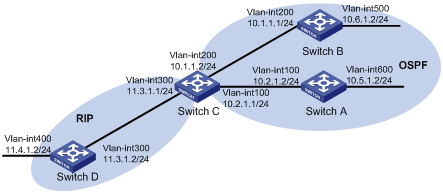
As shown in Figure 8, Switch A and Switch B run OSPF; Switch D runs RIP; and Switch C runs OSPF and RIP.
Configure RIP to redistribute OSPF routes on Switch C so Switch D has routes destined for networks 10.1.1.0/24, 10.2.1.0/24, 10.5.1.0/24, and 10.6.1.0/24.
Configure route summarization on Switch C to advertise only the summary route 10.0.0.0/8, reducing the routing table size of Switch D.
Configuration procedure
1. Configure IP addresses for interfaces. (Details not shown.)
2. Configure basic OSPF:
# Configure Switch A.
<SwitchA> system-view
[SwitchA] ospf
[SwitchA-ospf-1] area 0
[SwitchA-ospf-1-area-0.0.0.0] network 10.5.1.0 0.0.0.255
[SwitchA-ospf-1-area-0.0.0.0] network 10.2.1.0 0.0.0.255
[SwitchA-ospf-1-area-0.0.0.0] quit
# Configure Switch B.
<SwitchB> system-view
[SwitchB] ospf
[SwitchB-ospf-1] area 0
[SwitchB-ospf-1-area-0.0.0.0] network 10.1.1.0 0.0.0.255
[SwitchB-ospf-1-area-0.0.0.0] network 10.6.1.0 0.0.0.255
[SwitchB-ospf-1-area-0.0.0.0] quit
# Configure Switch C.
<SwitchC> system-view
[SwitchC] ospf
[SwitchC-ospf-1] area 0
[SwitchC-ospf-1-area-0.0.0.0] network 10.1.1.0 0.0.0.255
[SwitchC-ospf-1-area-0.0.0.0] network 10.2.1.0 0.0.0.255
[SwitchC-ospf-1-area-0.0.0.0] quit
3. Configure basic RIP:
# Configure Switch C.
<SwitchC> system-view
[SwitchC] rip 1
[SwitchC-rip-1] network 11.3.1.0
[SwitchC-rip-1] version 2
[SwitchC-rip-1] undo summary
# Configure Switch D.
<SwitchD> system-view
[SwitchD] rip 1
[SwitchD-rip-1] network 11.0.0.0
[SwitchD-rip-1] version 2
[SwitchD-rip-1] undo summary
[SwitchD-rip-1] quit
# Configure RIP to redistribute the routes from OSPF process 1 and direct routes on Switch C.
[SwitchC-rip-1] import-route direct
[SwitchC-rip-1] import-route ospf 1
# Display the routing table information of Switch D.
[SwitchD] display ip routing-table
Routing Tables: Public
Destinations : 10 Routes : 10
Destination/Mask Proto Pre Cost NextHop Interface
10.1.1.0/24 RIP 100 1 11.3.1.1 Vlan300
10.2.1.0/24 RIP 100 1 11.3.1.1 Vlan300
10.5.1.0/24 RIP 100 1 11.3.1.1 Vlan300
10.6.1.0/24 RIP 100 1 11.3.1.1 Vlan300
11.3.1.0/24 Direct 0 0 11.3.1.2 Vlan300
11.3.1.2/32 Direct 0 0 127.0.0.1 InLoop0
11.4.1.0/24 Direct 0 0 11.4.1.2 Vlan400
11.4.1.2/32 Direct 0 0 127.0.0.1 InLoop0
127.0.0.0/8 Direct 0 0 127.0.0.1 InLoop0
127.0.0.1/32 Direct 0 0 127.0.0.1 InLoop0
4. Configure route summarization:
Configure route summarization on Switch C and advertise only the summary route 10.0.0.0/8.
[SwitchC] interface vlan-interface 300
[SwitchC-Vlan-interface300] rip summary-address 10.0.0.0 8
# Display the routing table information on Switch D.
[SwitchD] display ip routing-table
Routing Tables: Public
Destinations : 7 Routes : 7
Destination/Mask Proto Pre Cost NextHop Interface
10.0.0.0/8 RIP 100 1 11.3.1.1 Vlan300
11.3.1.0/24 Direct 0 0 11.3.1.2 Vlan300
11.3.1.2/32 Direct 0 0 127.0.0.1 InLoop0
11.4.1.0/24 Direct 0 0 11.4.1.2 Vlan400
11.4.1.2/32 Direct 0 0 127.0.0.1 InLoop0
127.0.0.0/8 Direct 0 0 127.0.0.1 InLoop0
127.0.0.1/32 Direct 0 0 127.0.0.1 InLoop0
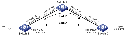
RIP FRR configuration example
Network requirements
Switch S, Switch A, and Switch D are interconnected through RIPv2, as illustrated in Figure 9. When Link A fails, services will be switched to Link B immediately.
Configuration procedure
1. Configure IP addresses and subnet masks for interfaces on the switches. (Details not shown.)
2. Configure RIPv2 on the switches to make sure Switch A, Switch D, and Switch S can communicate with each other at Layer 3 and dynamic route update can be implemented among them with RIPv2. (Details not shown.)
3. Configure RIP FRR:
# Configure Switch S.
<SwitchS> system-view
[SwitchS] bfd echo-source-ip 1.1.1.1
[SwitchS] ip ip-prefix abc index 10 permit 4.4.4.4 32
[SwitchS] route-policy frr permit node 10
[SwitchS-route-policy] if-match ip-prefix abc
[SwitchS-route-policy] apply fast-reroute backup-interface vlan-interface 100 backup-nexthop 12.12.12.2
[SwitchS-route-policy] quit
[SwitchS] rip 1
[SwitchS-rip-1] fast-reroute route-policy frr
[SwitchS-rip-1] quit
# Configure Switch D.
<SwitchD> system-view
[SwitchD] bfd echo-source-ip 4.4.4.4
[SwitchD] ip ip-prefix abc index 10 permit 1.1.1.1 32
[SwitchD] route-policy frr permit node 10
[SwitchD-route-policy] if-match ip-prefix abc
[SwitchD-route-policy] apply fast-reroute backup-interface vlan-interface 101 backup-nexthop 24.24.24.2
[SwitchD-route-policy] quit
[SwitchD] rip 1
[SwitchD-rip-1] fast-reroute route-policy frr
[SwitchD-rip-1] quit
4. Verify the configuration:
# Display route 4.4.4.4/32 on Switch S to view the backup next hop information.
[SwitchS] display ip routing-table 4.4.4.4 verbose
Routing Table : Public
Summary Count : 1
Destination: 4.4.4.4/32
Protocol: RIP Process ID: 1
Preference: 100 Cost: 1
IpPrecedence: QosLcId:
NextHop: 13.13.13.2 Interface: vlan200
BkNextHop: 12.12.12.2 BkInterface: vlan100
RelyNextHop: 0.0.0.0 Neighbor : 0.0.0.0
Tunnel ID: 0x0 Label: NULL
BKTunnel ID: 0x0 BKLabel: NULL
State: Active Adv Age: 00h01m27s
Tag: 0
# Display route 1.1.1.1/32 on Switch D to view the backup next hop information.
[SwitchD] display ip routing-table 1.1.1.1 verbose
Routing Table : Public
Summary Count : 1
Destination: 1.1.1.1/32
Protocol: RIP Process ID: 1
Preference: 100 Cost: 1
IpPrecedence: QosLcId:
NextHop: 13.13.13.1 Interface: vlan200
BkNextHop: 24.24.24.2 BkInterface: vlan101
RelyNextHop: 0.0.0.0 Neighbor : 0.0.0.0
Tunnel ID: 0x0 Label: NULL
BKTunnel ID: 0x0 BKLabel: NULL
State: Active Adv Age: 00h01m27s
Tag: 0
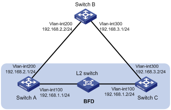
Configuring BFD for RIP (single-hop echo detection)
Network requirements
Switch A and Switch C are interconnected through a Layer 2 switch, as shown in Figure 10. VLAN-interface 100 of the two switches runs RIP process 1; BFD is enabled on VLAN-interface 100 of Switch A.
Switch A is connected to Switch C through Switch B. VLAN-interface 200 on Switch A runs RIP process 2; VLAN-interface 300 on Switch C, and VLAN-interface 200 and VLAN-interface 300 on Switch B run RIP process 1.
Configure a static route and enable static route redistribution into RIP on Switch C. Switch A learns the static route sent by Switch C, and the output interface of the route is the interface connected to the Layer 2 switch.
When the link between Switch C and the Layer 2 switch fails, BFD can quickly detect the link failure and notify it to RIP, and the BFD session goes down. In response, RIP deletes the neighbor relationship with Switch C and the route information received from Switch C. Then, Switch A learns the static route sent by Switch C, with the output interface being the interface connected to Switch B.
Configuration procedure
1. Configure IP addresses for interfaces. (Details not shown.)
2. Configure basic RIP:
# Configure Switch A.
<SwitchA> system-view
[SwitchA] rip 1
[SwitchA-rip-1] version 2
[SwitchA-rip-1] undo summary
[SwitchA-rip-1] network 192.168.1.0
[SwitchA-rip-1] quit
[SwitchA] interface vlan-interface 100
[SwitchA-Vlan-interface100] rip bfd enable
[SwitchA-Vlan-interface100] quit
[SwitchA] rip 2
[SwitchA-rip-2] version 2
[SwitchA-rip-2] undo summary
[SwitchA-rip-2] network 192.168.2.0
[SwitchA-rip-2] quit
# Configure Switch B.
<SwitchB> system-view
[SwitchB] rip 1
[SwitchB-rip-1] version 2
[SwitchB-rip-1] undo summary
[SwitchB-rip-1] network 192.168.2.0
[SwitchB-rip-1] network 192.168.3.0
[SwitchB-rip-1] quit
# Configure Switch C.
<SwitchC> system-view
[SwitchC] rip 1
[SwitchC-rip-1] version 2
[SwitchC-rip-1] undo summary
[SwitchC-rip-1] network 192.168.1.0
[SwitchC-rip-1] network 192.168.3.0
[SwitchC-rip-1] import-route static
[SwitchC-rip-1] quit
3. Configure BFD parameters on Switch A.
[SwitchA] bfd session init-mode active
[SwitchA] bfd echo-source-ip 11.11.11.11
[SwitchA] interface vlan-interface 100
[SwitchA-Vlan-interface100] bfd min-transmit-interval 500
[SwitchA-Vlan-interface100] bfd min-receive-interval 500
[SwitchA-Vlan-interface100] bfd detect-multiplier 7
[SwitchA-Vlan-interface100] quit
[SwitchA] quit
4. Configure a static route on Switch C.
[SwitchC] ip route-static 100.1.1.1 24 null 0
5. Verify the configuration:
# Display the BFD session information on Switch A.
<SwitchA> display bfd session
Total Session Num: 1 Init Mode: Active
Session Working Under Echo Mode:
LD SourceAddr DestAddr State Holdtime Interface
5 192.168.1.1 192.168.1.2 Up 2000ms Vlan100
# Display the RIP routes learned from Switch B on Switch A.
<SwitchA> display ip routing-table 100.1.1.0 24 verbose
Routing Table : Public
Summary Count : 2
Destination: 100.1.1.0/24
Protocol: RIP Process ID: 1
Preference: 100 Cost: 1
IpPrecedence: QosLcId:
NextHop: 192.168.1.2 Interface: vlan-interface 100
BkNextHop: 0.0.0.0 BkInterface:
RelyNextHop: 0.0.0.0 Neighbor : 192.168.1.2
Tunnel ID: 0x0 Label: NULL
BKTunnel ID: 0x0 BKLabel: NULL
State: Active Adv Age: 00h00m47s
Tag: 0
Destination: 100.1.1.0/24
Protocol: RIP Process ID: 2
Preference: 100 Cost: 2
IpPrecedence: QosLcId:
NextHop: 192.168.2.2 Interface: vlan-interface 200
BkNextHop: 0.0.0.0 BkInterface:
RelyNextHop: 0.0.0.0 Neighbor : 192.168.2.2
Tunnel ID: 0x0 Label: NULL
BKTunnel ID: 0x0 BKLabel: NULL
State: Inactive Adv Age: 00h12m50s
Tag: 0
# Enable RIP event debugging on Switch A.
<SwitchA> debugging rip 1 event
<SwitchA> terminal debugging
%Jan 19 10:41:51:203 2008 SwitchA BFD/4/LOG:Sess[192.168.1.1/192.168.1.2, Vlan-interface 100,Ctrl], Sta: UP->DOWN, Diag: 1
*Jan 19 10:33:12:813 2008 SwitchA RM/6/RMDEBUG: RIP-BFD: Message Type Disable, Connect Type Direct-connect, Pkt Type Echo, Src IP Address 192.168.1.1, Src IFIndex4, Nbr IP Address 192.168.1.2.
The output shows that when the link over VLAN-interface 100 fails, Switch A can quickly detect the change.
# Display the BFD information on Switch A.
<SwitchA> display bfd session
The output shows that Switch A has deleted the BFD session on VLAN-interface 100 to Switch C and displays no output.
# Display the RIP routes of RIP process 1 on Switch A.
<SwitchA> display rip 1 route
Route Flags: R - RIP, T - TRIP
P - Permanent, A - Aging, S - Suppressed, G - Garbage-collect
----------------------------------------------------------------------------
The output shows that the RIP route learned from Switch C no longer exists.
# Display routes destined for 100.1.1.0/24 learned on Switch A.
<SwitchA> display ip routing-table 100.1.1.0 24 verbose
Routing Table : Public
Summary Count : 1
Destination: 100.1.1.0/24
Protocol: RIP Process ID: 2
Preference: 100 Cost: 2
IpPrecedence: QosLcId:
NextHop: 192.168.2.2 Interface: vlan-interface 200
BkNextHop: 0.0.0.0 BkInterface:
RelyNextHop: 0.0.0.0 Neighbor : 192.168.2.2
Tunnel ID: 0x0 Label: NULL
BKTunnel ID: 0x0 BKLabel: NULL
State: Active Adv Age: 00h18m40s
Tag: 0
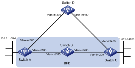
Configuring BFD for RIP (bidirectional control detection)
Network requirements
Switch A is connected to Switch C through Switch B, as shown in Figure 11. VLAN-interface 100 on Switch A and VLAN-interface 200 on Switch C run RIP process 1.
Configure a static route to Switch C on Switch A, and configure a static route to Switch A on Switch C. Enable BFD on VLAN-interface 100 of Switch A and VLAN-interface 200 of Switch C.
Switch A is connected to Switch C through Switch D. VLAN-interface 300 on Switch A runs RIP process 2; VLAN-interface 400 on Switch C, and VLAN-interface 300 and VLAN-interface 400 on Switch D run RIP process 1.
Enable static route redistribution into RIP on Switch A and Switch C so Switch A and Switch C have routes to send to each other. Switch A learns the static route sent by Switch C, the output interface is the interface connected to Switch B.
When the link between Switch B and Switch C fails, BFD can quickly detect the link failure and notify it to RIP, and the BFD session goes down. In response, RIP deletes the neighbor relationship with Switch C and the route information received from Switch C. Then, Switch A learns the static route sent by Switch C, with the output interface of the route being the interface connected to Switch D.
|
Device |
Interface |
IP address |
Device |
Interface |
IP address |
|
Switch A |
Vlan-int300 |
192.168.3.1/24 |
Switch B |
Vlan-int100 |
192.168.1.2/24 |
|
|
Vlan-int100 |
192.168.1.1/24 |
|
Vlan-int200 |
192.168.2.1/24 |
|
Switch C |
Vlan-int200 |
192.168.2.2/24 |
Switch D |
Vlan-int300 |
192.168.3.2/24 |
|
|
Vlan-int400 |
192.168.4.2/24 |
|
Vlan-int400 |
192.168.4.1/24 |
Configuration procedure
1. Configure IP addresses for interfaces. (Details not shown.)
2. Configure basic RIP and enable static route redistribution into RIP so Switch A and Switch C have routes to send to each other:
# Configure Switch A.
<SwitchA> system-view
[SwitchA] rip 1
[SwitchA-rip-1] version 2
[SwitchA-rip-1] undo summary
[SwitchA-rip-1] network 192.168.1.0
[SwitchA-rip-1] network 101.1.1.0
[SwitchA-rip-1] peer 192.168.2.2
[SwitchA-rip-1] undo validate-source-address
[SwitchA-rip-1] import-route static
[SwitchA-rip-1] quit
[SwitchA] interface vlan-interface 100
[SwitchA-Vlan-interface100] rip bfd enable
[SwitchA-Vlan-interface100] quit
[SwitchA] rip 2
[SwitchA-rip-2] version 2
[SwitchA-rip-2] undo summary
[SwitchA-rip-2] network 192.168.3.0
[SwitchA-rip-2] quit
# Configure Switch C.
<SwitchC> system-view
[SwitchC] rip 1
[SwitchC-rip-1] version 2
[SwitchC-rip-1] undo summary
[SwitchC-rip-1] network 192.168.2.0
[SwitchC-rip-1] network 192.168.4.0
[SwitchC-rip-1] network 100.1.1.0
[SwitchC-rip-1] peer 192.168.1.1
[SwitchC-rip-1] undo validate-source-address
[SwitchC-rip-1] import-route static
[SwitchC-rip-1] quit
[SwitchC] interface vlan-interface 200
[SwitchC-Vlan-interface200] rip bfd enable
[SwitchC-Vlan-interface200] quit
# Configure Switch D.
<SwitchD> system-view
[SwitchD] rip 1
[SwitchD-rip-1] version 2
[SwitchD-rip-1] undo summary
[SwitchD-rip-1] network 192.168.3.0
[SwitchD-rip-1] network 192.168.4.0
3. Configure BFD parameters:
# Configure Switch A.
[SwitchA] bfd session init-mode active
[SwitchA] interface vlan-interface 100
[SwitchA-Vlan-interface100] bfd min-transmit-interval 500
[SwitchA-Vlan-interface100] bfd min-receive-interval 500
[SwitchA-Vlan-interface100] bfd detect-multiplier 7
[SwitchA-Vlan-interface100] quit
# Configure Switch C.
[SwitchC] bfd session init-mode active
[SwitchC] interface vlan-interface 200
[SwitchC-Vlan-interface200] bfd min-transmit-interval 500
[SwitchC-Vlan-interface200] bfd min-receive-interval 500
[SwitchC-Vlan-interface200] bfd detect-multiplier 7
[SwitchC-Vlan-interface200] quit
4. Configure static routes:
# Configure a static route to Switch C on Switch A.
[SwitchA] ip route-static 192.168.2.0 24 vlan-interface 100 192.168.1.2
[SwitchA] quit
# Configure a static route to Switch A on Switch C.
[SwitchC] ip route-static 192.168.1.0 24 vlan-interface 200 192.168.2.1
5. Verify the configuration:
# Display the BFD session information of Switch A.
<SwitchA> display bfd session
Total Session Num: 1 Init Mode: Active
Session Working Under Ctrl Mode:
LD/RD SourceAddr DestAddr State Holdtime Interface
6/3 192.168.1.1 192.168.2.2 Up 1700ms vlan100
# Display RIP routes destined for 100.1.1.0/24 on Switch A.
<SwitchA> display ip routing-table 100.1.1.0 24 verbose
Routing Table : Public
Summary Count : 2
Destination: 100.1.1.0/24
Protocol: RIP Process ID: 1
Preference: 100 Cost: 1
IpPrecedence: QosLcId:
NextHop: 192.168.1.2 Interface: vlan-interface 100
BkNextHop: 0.0.0.0 BkInterface:
RelyNextHop: 0.0.0.0 Neighbor : 192.168.1.2
Tunnel ID: 0x0 Label: NULL
BKTunnel ID: 0x0 BKLabel: NULL
State: Active Adv Age: 00h00m47s
Tag: 0
Destination: 100.1.1.0/24
Protocol: RIP Process ID: 2
Preference: 100 Cost: 2
IpPrecedence: QosLcId:
NextHop: 192.168.3.2 Interface: vlan-interface 300
BkNextHop: 0.0.0.0 BkInterface:
RelyNextHop: 0.0.0.0 Neighbor : 192.168.3.2
Tunnel ID: 0x0 Label: NULL
BKTunnel ID: 0x0 BKLabel: NULL
State: Inactive Adv Age: 00h12m50s
Tag: 0
# Enable RIP event debugging on Switch A.
<SwitchA> debugging rip 1 event
<SwitchA> terminal debugging
%Jan 19 10:41:51:203 2008 SwitchA BFD/4/LOG:Sess[192.168.1.1/192.168.2.2, Vlan-interface 100, Ctrl], Sta: UP->DOWN, Diag: 1
*Jan 19 10:41:51:203 2008 SwitchA RM/6/RMDEBUG: RIP-BFD: Message Type Disable, Connect Type Indirect-connect, Pkt Type Control, Src IP Address 192.168.1.1, Src IFIndex 4, Nbr IP Address 192.168.2.2.
The output shows that when the link over VLAN-interface 100 fails, Switch A can quickly detect the link state change.
# Display the BFD information on Switch A.
<SwitchA> display bfd session
The output shows that Switch A has deleted the BFD session on VLAN-interface 100 to Switch C and displays no output.
# Display the RIP routes of RIP process 1 on Switch A.
<SwitchA> display rip 1 route
Route Flags: R - RIP, T - TRIP
P - Permanent, A - Aging, S - Suppressed, G - Garbage-collect
----------------------------------------------------------------------------
The output shows that the RIP route learned from Switch C no longer exists.
# Display RIP routes destined for 100.1.1.0/24 on Switch A.
<SwitchA> display ip routing-table 100.1.1.0 24 verbose
Routing Table : Public
Summary Count : 1
Destination: 100.1.1.0/24
Protocol: RIP Process ID: 2
Preference: 100 Cost: 2
IpPrecedence: QosLcId:
NextHop: 192.168.3.2 Interface: vlan-interface 300
BkNextHop: 0.0.0.0 BkInterface:
RelyNextHop: 0.0.0.0 Neighbor : 192.168.3.2
Tunnel ID: 0x0 Label: NULL
BKTunnel ID: 0x0 BKLabel: NULL
State: Active Adv Age: 00h18m40s
Tag: 0
Troubleshooting RIP
No RIP updates received
Symptom
No RIP updates are received when the links work well.
Analysis
After enabling RIP, use the network command to enable corresponding interfaces. Make sure no interfaces are disabled from handling RIP messages.
If the peer is configured to send multicast messages, the same should be configured on the local end.
Solution
1. Use the display current-configuration command to verify RIP configuration
2. Use the display rip command to verify whether some interface is disabled
Route oscillation occurred
Symptom
When all links work well, route oscillation occurs on the RIP network. After displaying the routing table, you might find some routes appear and disappear in the routing table intermittently.
Analysis
In the RIP network, make sure all the same timers within the entire network are identical and relationships between timers are reasonable. For example, the timeout timer value should be greater than the update timer value.
Solution
1. Use the display rip command to verify the configuration of RIP timers.
2. Use the timers command to adjust timers.