- Table of Contents
-
- 07-Layer 3 - IP Routing Configuration Guide
- 00-Preface
- 01-Basic IP Routing Configuration
- 02-Static Routing Configuration
- 03-RIP Configuration
- 04-OSPF Configuration
- 05-IS-IS Configuration
- 06-BGP Configuration
- 07-Policy-Based Routing Configuration
- 08-Guard Route Configuration
- 09-IPv6 Static Routing Configuration
- 10-RIPng Configuration
- 11-OSPFv3 Configuration
- 12-IPv6 IS-IS Configuration
- 13-IPv6 BGP Configuration
- 14-IPv6 Policy-Based Routing Configuration
- 15-Routing Policy Configuration
- 16-Tunnel End Packets Policy Routing Configuration
- Related Documents
-
| Title | Size | Download |
|---|---|---|
| 16-Tunnel End Packets Policy Routing Configuration | 144.78 KB |
Contents
Configuring tunnel end packets policy routing
Introduction to tunnel end packets policy routing
Configuring tunnel end packets policy routing
Tunnel end packets policy routing configuration examples
MPLS L3VPN tunnel end packets policy routing configuration example
GRE tunnel end packets policy routing configuration example
Introduction to tunnel end packets policy routing
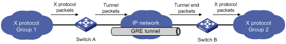
A tunnel end device refers to a device where the outgoing interface of a tunnel resides. Tunneled packets that a tunnel end device receives are tunnel end packets. In the example shown in Figure 1, Switch B is a tunnel end device, and packets that Switch B receives are tunnel end packets. The tunnel end device de-encapsulates tunnel end packets, and then forwards them to the X protocol network. To implement policy routing of tunnel end packets, use QoS policy routing instead of policy-based routing (PBR).
Figure 1 X protocol network interconnection through a GRE tunnel
Different from the traditional destination-based routing mechanism, QoS policy routing makes routing decisions based on the source address and other criteria. For more information about QoS policies, see ACL and QoS Configuration Guide.
QoS policy routing takes precedence over destination-based routing. QoS policy routing applies to the packets matching the specified criteria, and other packets are forwarded through destination-based routing.
|
|
IMPORTANT: To specify a next hop for the traffic redirecting action of a QoS policy, you cannot specify an MPLS L3VPN instance at the same time, so MPLS L3VPN tunnel packets can only be redirected to a public network interface. For more information about MPLS L3VPN, see MPLS Configuration Guide. |
Configuring tunnel end packets policy routing
You can implement policy routing of tunnel end packets by configuring and applying a QoS policy on the tunnel end device.
For information about relevant commands, see ACL and QoS Command Reference.
Configuring a QoS policy
|
Step |
Command |
|
1. Enter system view. |
system-view |
|
2. Create a class and enter class view. |
traffic classifier tcl-name [ operator { and | or } ] |
|
3. Configure the match criteria. |
if-match [ not ] match-criteria |
|
4. Exit to system view. |
quit |
|
5. Create a traffic behavior and enter traffic behavior view. |
traffic behavior behavior-name |
|
6. Configure the action of redirecting traffic to the next hop. |
redirect next-hop { ipv4-add1 [ track track-entry-number ] [ ipv4-add2 [ track track-entry-number ] ] | ipv6-add1 [ interface-type interface-number ] [ track track-entry-number ] [ ipv6-add2 [ interface-type interface-number ] [ track track-entry-number ] ] } [ fail-action { discard | forward } ] |
|
7. Exit to system view. |
quit |
|
8. Create a QoS policy and enter QoS policy view. |
qos policy policy-name |
|
9. Associate the traffic behavior with the class. |
classifier tcl-name behavior behavior-name |
Applying the QoS policy
You can apply a QoS policy globally, to interfaces, or to VLANs:
· Applied globally, the QoS policy takes effect on all traffic received on the device.
· Applied to an interface, the QoS policy takes effect on the traffic received on the interface.
· Applied to a VLAN, the QoS policy takes effect on the traffic received on all ports in the VLAN.
The QoS policy used for configuring policy routing can be applied in only the inbound direction.
To apply the QoS policy globally:
|
Step |
Command |
|
1. Enter system view. |
system-view |
|
2. Apply the QoS policy globally in the inbound direction. |
qos apply policy policy-name global inbound |
To apply the QoS policy to interfaces:
|
Step |
Command |
Remarks |
|
1. Enter system view. |
system-view |
N/A |
|
2. Enter Layer 2 Ethernet interface view or port group view. |
· Enter Layer 2 Ethernet interface view: · Enter port group view: |
Use either method. Settings made in interface view take effect on the interface only. Settings made in port group view take effect on all ports in the port group. |
|
3. Apply the QoS policy to the interface or interfaces in the port group in the inbound direction. |
qos apply policy policy-name inbound |
N/A |
To apply the QoS policy to VLANs:
|
Step |
Command |
Remarks |
|
1. Enter system view. |
system-view |
N/A |
|
2. Apply the QoS policy to VLANs in the inbound direction. |
qos vlan-policy policy-name vlan vlan-id-list inbound |
QoS policies cannot be applied to dynamic VLANs, for example, VLANs created by GVRP. |
Tunnel end packets policy routing configuration examples
MPLS L3VPN tunnel end packets policy routing configuration example
Network requirements
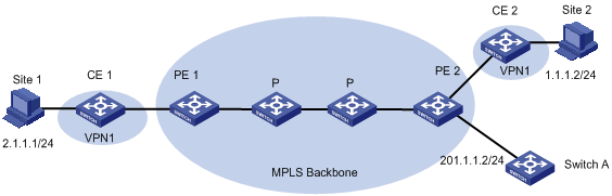
As shown in Figure 2, both CE 1 and CE 2 belong to VPN 1, and an MPLS L3VPN tunnel is established between CE 1 and CE 2. Configure a QoS policy on PE 2 to redirect packets of VPN 1 that are destined for CE 2 to the next hop 201.1.1.2.
Configuration procedure
# Create ACL 2000, and configure a rule to match packets of VPN 1.
<PE2> system-view
[PE2] acl number 2000
[PE2-acl-basic-2000] rule 10 permit vpn-instance vpn1
[PE2-acl-basic-2000] quit
# Create a class named a, and use ACL 2000 as the match criterion in the class.
[PE2] traffic classifier a
[PE2-classifier-a] if-match acl 2000
[PE2-classifier-a] quit
# Create a behavior named a, and configure the action of redirecting traffic to the next hop 201.1.1.2.
[PE2] traffic behavior a
[PE2-behavior-a] redirect next-hop 201.1.1.2
[PE2-behavior-a] quit
# Create a policy named a, and associate class a with behavior a in the policy.
[PE2] qos policy a
[PE2-qospolicy-a] classifier a behavior a
[PE2-qospolicy-a] quit
# Apply the policy globally in the inbound direction.
[PE2] qos apply policy a global inbound
Verifying the configuration
After you complete the configuration, verify that when PE 2 receives packets of VPN 1, it forwards the packets to Switch A instead of CE 2.
GRE tunnel end packets policy routing configuration example
Network requirements
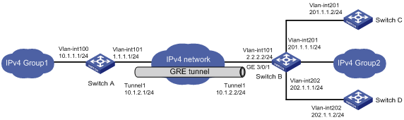
As shown in Figure 3, Switch A and Switch B are connected over the Internet. Group 1 and Group 2 are two private networks interconnected through a GRE tunnel configured on two switches. Configure a QoS policy on Switch B to redirect packets destined for 201.1.1.2 to the next hop 202.1.1.2.
Configuration procedure
# Create ACL 3000, and configure a rule to match packets with the destination IP address 201.1.1.2/32.
<SwitchB> system-view
[SwitchB] acl number 3000
[SwitchB-acl-basic-3000] rule 0 permit ip destination 201.1.1.2 0
[SwitchB-acl-basic-3000] quit
# Create a class named a, and use ACL 3000 as the match criterion in the class.
[SwitchB] traffic classifier a
[SwitchB-classifier-a] if-match acl 3000
[SwitchB-classifier-a] quit
# Create a behavior named a, and configure the action of redirecting traffic to the next hop 202.1.1.2.
[SwitchB] traffic behavior a
[SwitchB-behavior-a] redirect next-hop 202.1.1.2
[SwitchB-behavior-a] quit
# Create a policy named a, and associate class a with behavior a in the policy.
[SwitchB] qos policy a
[SwitchB-qospolicy-a] classifier a behavior a
[SwitchB-qospolicy-a] quit
# Apply the policy to the incoming traffic of GigabitEthernet 3/0/1.
[SwitchB] interface GigabitEthernet 3/0/1
[SwitchB-GigabitEthernet3/0/1] qos apply policy a inbound
Verifying the configuration
After you complete the configuration, verify that when Switch B receives packets with the destination IP address 201.1.1.2, it forwards the packets to Switch D instead of Switch C.