- Table of Contents
- Related Documents
-
| Title | Size | Download |
|---|---|---|
| 03-FR QoS Configuration | 138.14 KB |
Contents
FR QoS configuration task list
Creating and configuring an FR class
Displaying and maintaining FR QoS
Overview
FR QoS allows you to deploy QoS (frame relay traffic shaping) on a per-PVC basis on an FR interface. By configuring Committed Information Rate Allowed (CIR ALLOW), you can guarantee CIR ALLOW for user data transmission when no congestion occurs in an FR network.
Why FRTS
Frame Relay Traffic Shaping (FRTS) limits the outgoing traffic rate of a PVC to avoid traffic congestion at the receiving device.
FRTS applies to the outgoing interface of a switch. You can use FRTS to remove the bottleneck created when the input rate of a device is slower than the output rate of the sending device.
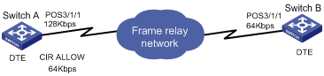
As shown in Figure 1, Switch A transmits packets to Switch B at 128 kbps whereas the maximum interface rate of Switch B is only 64 kbps. This traffic rate disparity creates a bottleneck at the interface that connects Switch B to the FR network. To avoid packet loss, you can use FRTS at the outgoing interface POS 3/1/1 of Switch A so the interface can transmit packets constantly at 64 kbps.
The FRTS implementation on the S9500E switches use the CIR ALLOW parameter for limiting traffic rates. You can configure a FR PVC to transmit packets at the rate of CIR ALLOW.
How FRTS works
FRTS is implemented using token buckets. The meanings of the related parameters in the protocol are modified as required by the actual algorithm and principles. See Figure 2 for how a token bucket works.
Figure 2 How a token bucket works
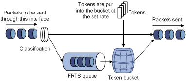
In the token bucket approach, packets requiring traffic control are put into the token bucket for processing before being sent out. If enough tokens are available in the token bucket for sending these packets, the packets are sent out. If the number of tokens in the token bucket is not enough for sending these packets, these packets are put into the FR class queue (that is the FRTS queue in FRTS implementation). Once enough tokens are available in the token bucket, the packets are taken out of the FR class queue for transmission. In this way, you can control the traffic of a certain class of packets. Tokens are in the unit of bits.
The FR protocol-provisioned related parameters correspond to the FRTS parameters as such: CIR ALLOW defines the number of tokens put into the token bucket per second.
FR QoS configuration task list
|
Task |
Remarks |
|
Required. |
|
|
Required. |
Creating and configuring an FR class
An FR class specifies a set of QoS parameters for traffic control and regulation on FR PVCs. To provide QoS on a PVC, you must create an FR class, set QoS parameters, such as FRTS settings in the class, and maps the class to the PVC.
You can map an FR class to PVCs by mapping it to FR main interfaces, subinterfaces, or DLCIs.
· The FR class mapped to an FR main interface takes effect on all PVCs on the FR main interface, including the PVCs on subinterfaces.
· The FR class mapped to an FR subinterface takes effect on all PVCs on the FR subinterface.
· The FR class mapped to a DLCI takes effect only on the PVC identified by the DLCI.
A QoS-capable FR PVC selects an FR class in the following order:
· The FR class mapped to the DLCI
· The FR class mapped to the FR subinterface
· The FR class mapped to the main interface
To configure and create an FR class:
|
Step |
Command |
Remarks |
|
1. Enter system view. |
system-view |
N/A |
|
2. Create an FR class and enter FR class view. |
fr class class-name |
By default, no FR class is created. |
|
3. Return to system view. |
quit |
N/A |
|
4. Map the FR class to an FR main interface, subinterface, or DLCI. |
· (Method 1) Map the FR class to an FR main interface or subinterface: a. Enter FR main interface view or FR subinterface view: b. Map the FR class to the FR interface: · (Method 2) Map the FR class to an DLCI: a. Enter FR main interface view or FR subinterface view: b. Enter FR PVC view: c. Map the FR
class to the DLCI: |
Use either method or both methods. By default, no FR class is mapped to any FR main interface, subinterface, or DLCI. |
|
|
NOTE: · You can configure FRTS settings in an FR class after you use the fr class command to create the FR class and enter FR class view. If you configure no parameters, the default CIR, 56000 bps, applies. · To make the FR class configuration take effect, you must enable FRTS on the FR main interface. |
Configuring FRTS
|
Step |
Command |
Remarks |
|
1. Enter system view. |
system-view |
N/A |
|
2. Enter FR interface view. |
interface interface-type interface-number |
N/A |
|
3. Enable FRTS. |
fr traffic-shaping |
By default, FRTS is disabled. |
|
4. Exit FR interface view. |
quit |
N/A |
|
5. Enter FR class view. |
fr class class-name |
N/A |
|
6. Set CIR ALLOW for FR PVCs. |
cir allow [ inbound | outbound ] committed-information-rate |
Optional. The default setting is 56000 bps. |
|
|
NOTE: · FRTS is applied to the interfaces sending FR packets and is usually applied to the DTE side of an FR network. · You can configure FRTS on only an FR main interface. The FRTS configuration takes effect on the FR main interface and all the DLCIs of the FR subinterfaces. |
Displaying and maintaining FR QoS
|
Task |
Command |
Remarks |
|
Display the mapping relationship between FR classes and interfaces (including the DLCIs of an interface, subinterfaces of an interface, and the DLCIs of subinterfaces). |
display fr class-map { fr-class class-name | interface interface-type interface-number } [ | { begin | exclude | include } regular-expression ] |
Available in any view. |
|
Display the statistics about data transmitted and received through FR. |
display fr statistics [ interface interface-type interface-number ] [ | { begin | exclude | include } regular-expression ] |
Available in any view. |
FR QoS configuration example
Network requirements
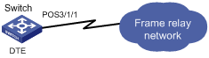
As shown in Figure 3, limit the average transmit rate of the switch to 96 kbps.
Configuration procedure
# Create an FR class and configure FRTS parameters for the FR class.
<Switch> system-view
[Switch] fr class 96k
[Switch-fr-class-96k] cir allow 96000
[Switch-fr-class-96k] quit
# Enable Frame Relay encapsulation on interface POS 3/1/1, and enable FRTS on it.
[Switch] interface Pos 3/1/1
[Switch-Pos3/1/1] link-protocol fr
[Switch-Pos3/1/1] ip address 1.1.1.1 255.255.255.0
[Switch-Pos3/1/1] fr traffic-shaping
# Create an FR PVC and associate the FR PVC with FR class 96k.
[Switch-Pos3/1/1] fr dlci 16
[Switch-fr-dlci-Pos3/1/1-16] fr-class 96k