- Table of Contents
- Related Documents
-
| Title | Size | Download |
|---|---|---|
| 02-QoS Configuration | 901.58 KB |
Contents
QoS processing flow in a device
QoS configuration approach overview
Displaying and maintaining QoS policies
Introduction to priority mapping
Priority mapping configuration tasks
Configuring a priority mapping table
Configuring a port to trust packet priority for priority mapping
Changing the port priority of an interface
Displaying and maintaining priority mapping
Priority mapping configuration example
Configuring traffic policing and traffic shaping
Traffic evaluation and token buckets
Displaying and maintaining traffic policing and GTS
Configuring congestion management
Causes, impacts, and countermeasures of congestion
Congestion management policies
Congestion management technique comparison
Displaying and maintaining CBQ
Configuring hardware congestion management
Causes, impacts, and countermeasures
Congestion management techniques
Hardware congestion management configuration approaches
Configuring per-queue hardware congestion management
Configuring hardware congestion management with queue scheduling profiles
Introduction to queue scheduling profile
Configuring a queue scheduling profile
Displaying and maintaining queue scheduling profiles
Queue scheduling profile configuration example
Displaying and maintaining CBQ
Configuring congestion avoidance·
Introduction to WRED configuration
Introduction to WRED parameters
Configuring WRED on an interface
Applying a WRED table on an interface
Displaying and maintaining WRED
Traffic filtering configuration restrictions
Traffic filtering configuration example
Configuring protocol packet rate limiting
Protocol packet rate limiting configuration example
Priority marking configuration example
Configuring traffic redirecting
Configuration restrictions and guidelines
Traffic redirecting configuration example
Configuring class-based accounting·
Displaying and maintaining class-based accounting
Class-based accounting configuration example
Configuring traffic accounting
Displaying and maintaining traffic accounting
Appendix B Default priority mapping tables
Introduction to priority mapping tables
Introduction to colored priority mapping tables
Appendix C Introduction to packet precedences
For more information about the subcards and Ethernet interface cards mentioned in this document, see the installation guide for the product.
Introduction to QoS
In data communications, Quality of Service (QoS) is the ability of a network to provide differentiated service guarantees for diversified traffic in terms of bandwidth, delay, jitter, and drop rate.
Network resources are scarce. The contention for resources requires that QoS prioritize important traffic flows over trivial ones. For example, when bandwidth is fixed, more bandwidth for one traffic flow means less bandwidth for the other traffic flows. When making a QoS scheme, you must consider the characteristics of various applications to balance the interests of diversified users and to utilize network resources.
The following section describes some typical QoS service models and widely used, mature QoS techniques.
QoS service models
Best-effort service model
Best effort is a single-service model and also the simplest service model. In the best-effort service model, the network does its best to deliver packets, but does not guarantee delay or reliability.
The best-effort service model is the default model in the Internet and applies to most network applications. It uses the first in first out (FIFO) queuing mechanism.
IntServ model
The integrated service (IntServ) model is a multiple-service model that can accommodate diverse QoS requirements. It provides the most granularly differentiated QoS by identifying and guaranteeing definite QoS for each data flow.
In the IntServ model, an application must request service from the network before it sends data. IntServ signals the service request with the Resource Reservation Protocol (RSVP). All nodes receiving the request reserve resources as requested and maintain state information for the application flow.
The IntServ model demands high storage and processing capabilities because it requires all nodes along the transmission path to maintain resource state information for each flow. The model is suitable for small-sized or edge networks, but not large-sized networks, for example, the core layer of the Internet, where billions of flows are present. For more information about RSVP, see MPLS Configuration Guide.
DiffServ model
The differentiated service (DiffServ) model is a multiple-service model that can meet diverse QoS requirements. It is easy to implement and extend. DiffServ does not signal the network to reserve resources before sending data, as IntServ does.
All QoS techniques in this document are based on the DiffServ model.
QoS techniques overview
The QoS techniques include traffic classification, traffic policing, traffic shaping, line rate, congestion management, and congestion avoidance. The following sections briefly introduce these QoS techniques.
Deploying QoS in a network
Figure 1 Position of the QoS techniques in a network
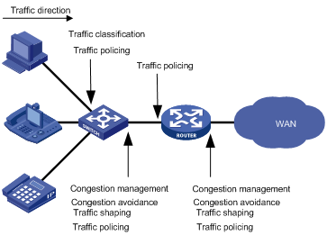
As shown in Figure 1, traffic classification, traffic shaping, traffic policing, congestion management, and congestion avoidance mainly implement the following functions:
· Traffic classification uses certain match criteria to assign packets with the same characteristics to a class. Based on classes, you can provide differentiated services.
· Traffic policing polices flows entering or leaving a device, and imposes penalties on traffic flows that exceed the pre-set threshold to prevent aggressive use of network resources. You can apply traffic policing to both incoming and outgoing traffic of a port.
· Traffic shaping proactively adapts the output rate of traffic to the network resources available on the downstream device to eliminate packet drops. Traffic shaping usually applies to the outgoing traffic of a port.
· Congestion management provides a resource scheduling policy to determine the packet forwarding sequence when congestion occurs. Congestion management usually applies to the outgoing traffic of a port.
· Congestion avoidance monitors the network resource usage, and is usually applied to the outgoing traffic of a port. When congestion worsens, congestion avoidance reduces the queue length by dropping packets.
QoS processing flow in a device
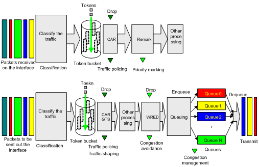
Figure 2 briefly describes how the QoS module processes traffic:
1. Traffic classifier identifies and classifies traffic for subsequent QoS actions.
2. The QoS module takes various QoS actions on classified traffic as configured, depending on the traffic processing phase and network status. For example, you can configure the QoS module to perform traffic policing for incoming traffic, traffic shaping for outgoing traffic, congestion avoidance before congestion occurs, and congestion management when congestion occurs.
QoS configuration approaches
QoS configuration approach overview
You can configure QoS in these approaches:
Some features support both approaches, but some support only one.
MQC approach
In the modular QoS configuration (MQC) approach, you configure QoS service parameters by using QoS policies. A QoS policy defines the shaping, policing, or other QoS actions to take on different classes of traffic. It is a set of class-behavior associations.
A class is a set of match criteria for identifying traffic, and it uses the AND or OR operator:
· If the operator is AND, a packet must match all the criteria to match the class.
· If the operator is OR, a packet matches the class if it matches any of the criteria in the class.
A traffic behavior defines a set of QoS actions to take on packets, such as priority marking and redirect.
By associating a traffic behavior with a class in a QoS policy, you apply the specific set of QoS actions to the class of traffic.
Non-MQC approach
In the non-MQC approach, you configure QoS service parameters without using a QoS policy. For example, you can use the line rate feature to set a rate limit on an interface without using a QoS policy.
Configuring a QoS policy
Figure 3 shows how to configure a QoS policy.
Figure 3 QoS policy configuration procedure

Defining a class
|
Step |
Command |
Remarks |
|
1. Enter system view. |
system-view |
N/A |
|
2. Create a class and enter class view. |
traffic classifier tcl-name [ operator { and | or } ] |
By default, the operator of a class is AND. The operator of a class can be AND or OR. · AND—A packet is assigned to a class only when the packet matches all the criteria in the class. Using AND as the operator in a class, you must make sure no conflict exists between the if-match clauses or the parameters in each if-match clause, and you can configure only one ACL for the class. · OR—A packet is assigned to a class if it matches any of the criteria in the class. |
|
3. Configure match criteria. |
if-match match-criteria |
For more information, see the if-match command in ACL and QoS Command Reference. |
Defining a traffic behavior
A traffic behavior is a set of QoS actions (such as traffic filtering, shaping, policing, and priority marking) to take on a class of traffic.
To define a traffic behavior:
|
Step |
Command |
Remarks |
|
1. Enter system view. |
system-view |
N/A |
|
2. Create a traffic behavior and enter traffic behavior view. |
traffic behavior behavior-name |
N/A |
|
3. Configure actions in the traffic behavior. |
See the subsequent chapters, depending on the purpose of the traffic behavior: traffic policing, traffic filtering, traffic redirecting, priority marking, traffic accounting, and so on. |
|
Defining a policy
You associate a behavior with a class in a QoS policy to perform the actions defined in the behavior for the class of packets.
To associate a class with a behavior in a policy:
|
Step |
Command |
Remarks |
|
1. Enter system view. |
system-view |
N/A |
|
2. Create a policy and enter policy view. |
qos policy policy-name |
N/A |
|
3. Associate a class with a behavior in the policy. |
classifier tcl-name behavior behavior-name |
Repeat this step to create more class-behavior associations. |
|
IMPORTANT: When an ACL is referenced by a QoS policy for traffic classification, the deny action in an ACL rule means not to execute the behavior of the corresponding class-behavior association, and the permit action in an ACL rule means to execute the behavior of the corresponding class-behavior association. |
Applying the QoS policy
You can apply a QoS policy to the following destinations:
· An interface—The policy takes effect on the traffic sent or received on the interface.
· A VLAN—The policy takes effect on the traffic sent or received on all ports in the VLAN.
· Globally—The policy takes effect on the traffic sent or received on all ports.
· Control plane—The policy takes effect on the traffic sent on the control plane.
Configuration restrictions and guidelines
· You can apply a QoS policy to the control plane of only an Ethernet interface card.
· You can modify classes, behaviors, and class-behavior associations in a QoS policy even after it is applied. If a class references an ACL for traffic classification, you can delete or modify the ACL (such as add rules to, delete rules from, and modify rules of the ACL).
· Global QoS policies, interface QoS policies, and VLAN QoS policies are in the descending order of priority when being used to match packets.
· Global QoS policies and VLAN QoS policies will be applied to all interface cards. If the hardware resources of an interface card are insufficient, applying a global or VLAN-based QoS policy will fail on the interface card. In this case, the system does not automatically roll back the QoS policy configuration already applied to the main processing unit or other interface cards. To ensure consistency, you must manually remove the QoS policy configuration applied to them. Do the same procedure if a global or VLAN-based QoS policy fails to update on an interface card after being dynamically modified.
Applying the QoS policy to an interface
A policy can be applied to multiple interfaces, but only one policy can be applied in one direction (inbound or outbound) of an interface.
When you apply a QoS policy to an interface, follow these guidelines:
· You can apply QoS policies to all physical interfaces but X.25- or LAPB-enabled interfaces.
· The QoS policy applied to the outgoing traffic on an interface does not regulate local packets, which are critical protocol packets sent by the local system for operation maintenance. The most common local packets include link maintenance, routing (IS-IS, BGP, and OSPF for example), RIP, LDP, RSVP, and SSH packets.
· A QoS policy to be applied to a logical RPR interface can be configured with only the filter action or mirror-to action. For more information about logical RPR interfaces, see High Availability Configuration Guide. For more information about the mirror-to action, see Network Management and Monitoring Configuration Guide.
To apply the QoS policy to an interface:
|
Step |
Command |
Remarks |
|
1. Enter system view. |
system-view |
N/A |
|
2. Enter interface view or port group view. |
· Enter interface view: · Enter port group view: |
Use either command. Settings in interface view take effect on the current interface. Settings in port group view take effect on all ports in the port group. |
|
3. Apply the policy to the interface or port group. |
qos apply policy policy-name { inbound | outbound } |
N/A |
Applying the QoS policy to a VLAN
You can apply a QoS policy to a VLAN to regulate traffic of the VLAN.
To apply the QoS policy to a VLAN:
|
Step |
Command |
|
1. Enter system view. |
system-view |
|
2. Apply the QoS policy to VLANs. |
qos vlan-policy policy-name vlan vlan-id-list { inbound | outbound } |
|
|
NOTE: · QoS policies cannot be applied to dynamic VLANs, for example, VLANs created by GVRP. · VLAN QoS policies are applied globally to all interface cards. If the hardware resources of an interface card are insufficient, applying a QoS policy to VLANs will fail on the interface card. The system does not automatically roll back the QoS policy configuration already applied to the main processing unit or other interface cards. To ensure consistency, use the undo qos vlan-policy vlan command to manually remove the QoS policy configuration applied to them. |
Applying the QoS policy globally
You can apply a QoS policy globally to the inbound or outbound direction of all ports.
To apply the QoS policy globally:
|
Step |
Command |
|
1. Enter system view. |
system-view |
|
2. Apply the QoS policy globally. |
qos apply policy policy-name global { inbound | outbound } |
|
|
NOTE: If the hardware resources of an interface card are insufficient, applying a QoS policy globally will fail on the interface card. The system does not automatically roll back the QoS policy configuration already applied to the main processing unit or other interface cards. To ensure consistency, you must use the undo qos apply policy global command to manually remove the QoS policy configuration applied to them. |
Applying the QoS policy to the control plane
When you apply the QoS policy to the control plane, follow these restrictions and guidelines:
· You can apply a QoS policy to the control plane of only an Ethernet interface card.
· By default, the switch is configured with pre-defined control plane policies, which take effect on the control planes by default. A pre-defined control plane QoS policy uses the system-index to identify the type of packets sent to the control plane. You can reference system-indexes in if-match commands in class view for traffic classification and then re-configure traffic behaviors for these classes as required. You can use the display qos policy control-plane pre-defined command to display them.
· When you apply a QoS policy to the control plane of the slot where the IRF port resides, if a class in the QoS policy uses an Ethernet frame header ACL configured with rule permit to match all packets, do not configure car cir or filter deny in the behavior associated with the class. Otherwise, the IRF might split, and the switch cannot work correctly.
The packets entering a device can be processed by the data plane or the control plane.
· The units at the data plane are responsible for receiving, transmitting, and switching (forwarding) packets, such as various dedicated forwarding chips. They deliver super processing speeds and throughput.
· The units at the control plane are processing units running most routing and switching protocols and responsible for protocol packet resolution and calculation, such as CPUs. Compared with data plane units, they allow for great packet processing flexibility but have lower throughput.
When the data plane receives packets that it cannot recognize or process, it transmits them to the control plane. If the transmission rate exceeds the processing capability of the control plane, which very likely occurs at times of DoS attacks, the control plane will be busy handling undesired packets and fail to handle packets correctly or timely. As a result, protocol performance is affected.
To address this problem, apply a QoS policy to the control plane to take QoS actions such as traffic filtering or rate limiting on inbound traffic, ensuring that the control plane can receive, transmit, and process packets properly.
To apply the QoS policy to the control plane:
|
Step |
Command |
|
1. Enter system view. |
system-view |
|
2. Enter control plane view. |
· In standalone mode: · In IRF mode: |
|
3. Apply the QoS policy to the control plane. |
qos apply policy policy-name inbound |
Displaying and maintaining QoS policies
|
Task |
Command |
Remarks |
|
Display traffic class configuration. |
display traffic classifier user-defined [ tcl-name ] [ | { begin | exclude | include } regular-expression ] |
Available in any view. |
|
Display traffic behavior configuration. |
display traffic behavior user-defined [ behavior-name ] [ | { begin | exclude | include } regular-expression ] |
Available in any view. |
|
Display user-defined QoS policy configuration. |
display qos policy user-defined [ policy-name [ classifier tcl-name ] ] [ | { begin | exclude | include } regular-expression ] |
Available in any view. |
|
Display QoS policy configuration on the specified or all interfaces. |
display qos policy interface [ interface-type interface-number ] [ inbound | outbound ] [ | { begin | exclude | include } regular-expression ] |
Available in any view. |
|
Display VLAN QoS policy configuration (in standalone mode). |
display qos vlan-policy { name policy-name | vlan vlan-id } [ slot slot-number ] [ inbound | outbound ] [ | { begin | exclude | include } regular-expression ] |
Available in any view. |
|
Display VLAN QoS policy configuration (in IRF mode). |
display qos vlan-policy { name policy-name | vlan [ vlan-id ] } [ chassis chassis-number slot slot-number ] [ inbound | outbound ] [ | { begin | exclude | include } regular-expression ] |
Available in any view. |
|
Display information about QoS policies applied globally (in standalone mode). |
display qos policy global [ slot slot-number ] [ inbound | outbound ] [ | { begin | exclude | include } regular-expression ] |
Available in any view. |
|
Display information about QoS policies applied globally (in IRF mode). |
display qos policy global [ chassis chassis-number slot slot-number ] [ inbound | outbound ] [ | { begin | exclude | include } regular-expression ] |
Available in any view. |
|
Display information about QoS policies applied to a control plane on (in standalone mode). |
display qos policy control-plane slot slot-number [ inbound ] [ | { begin | exclude | include } regular-expression ] |
Available in any view. |
|
Display information about pre-defined QoS policies applied to the control plane (in IRF mode). |
display qos policy control-plane chassis chassis-number slot slot-number [ inbound ] [ | { begin | exclude | include } regular-expression ] |
Available in any view. |
|
Display information about pre-defined QoS policies applied to a control plane (in standalone mode). |
display qos policy control-plane pre-defined slot slot-number [ | { begin | exclude | include } regular-expression ] |
Available in any view. |
|
Display information about pre-defined QoS policies applied to a control plane (in IRF mode). |
display qos policy control-plane pre-defined chassis chassis-number slot slot-number [ | { begin | exclude | include } regular-expression ] |
Available in any view. |
|
Clear VLAN QoS policy statistics. |
reset qos vlan-policy [ vlan vlan-id ] [ inbound | outbound ] |
Available in user view. |
|
Clear the statistics for a QoS policy applied globally. |
reset qos policy global [ inbound | outbound ] |
Available in user view. |
|
Clear the statistics for the QoS policy applied to a control plane (in standalone mode). |
reset qos policy control-plane slot slot-number [ inbound ] |
Available in user view. |
|
Clear the statistics for the QoS policy applied to a control plane (in IRF mode). |
reset qos policy control-plane chassis chassis-number slot slot-number [ inbound ] |
Available in user view. |
|
|
NOTE: To clear statistics for an interface, use the reset counters interface command. For more information about the reset counters interface command, see Interface Command Reference. |
Overview
Introduction to priority mapping
When a packet arrives, a device assigns a set of QoS priority parameters to the packet based on a certain priority field carried in the packet or the port priority of the incoming port, depending on your configuration. This process is called "priority mapping". During this process, the device can modify the priority of the packet depending on device status. The set of QoS priority parameters decides the scheduling priority and forwarding priority of the packet.
Priority mapping is implemented with priority mapping tables and involves priorities such as 802.11e priority, 802.1p priority, DSCP, EXP, IP precedence, local precedence, and drop precedence.
Introduction to priorities
Priorities include the following types: priorities carried in packets, and priorities locally assigned for scheduling only.
The packet carried priorities include 802.1p priority, DSCP precedence, IP precedence, EXP, and so on. These priorities have global significance and affect the forwarding priority of packets across the network. For more information about these priorities, see "Appendix."
The locally assigned priorities have only local significance. They are assigned by the device for scheduling only. These priorities include the local precedence, drop precedence, and user precedence, as follows.
· Local precedence is used for queuing. A local precedence value corresponds to an output queue. A packet with higher local precedence is assigned to a higher priority output queue to be preferentially scheduled.
· Drop precedence is used for making packet drop decisions. Packets with the highest drop precedence are dropped preferentially.
· User precedence is the precedence that the device automatically extracts from a certain priority field of the packet according to its forwarding path. The user precedence represents the 802.1p precedence for Layer-2 packets, the IP precedence for Layer-3 packets, and the EXP precedence for MPLS packets.
Priority mapping tables
The device provides various types of priority mapping tables, or rather, priority mappings. By looking up a priority mapping table, the device decides which priority value is to assign to a packet for subsequent packet processing.
The default priority mapping tables (as shown in Appendix B Default priority mapping tables) are available for priority mapping. They are adequate in most cases. If a default priority mapping table cannot meet your requirements, you can modify the priority mapping table as required.
Priority mapping configuration tasks
You can configure priority mapping in any of the following approaches:
· Configuring priority trust mode.
In this approach, you can configure a port to look up a certain priority, 802.1p for example, in incoming packets, in the priority mapping tables. If no packet priority is trusted, the port priority of the incoming port is used.
· Changing port priority.
By default, all ports are assigned the port priority of zero. By changing the port priority of a port, you change the priority of the incoming packets on the port.
· Configuring a QoS policy containing the priority mapping (simply called "primap") action with the primap command.
Perform these tasks to configure priority mapping:
|
Task |
Remarks |
|
Optional. |
|
|
Configuring a port to trust packet priority for priority mapping |
Optional. |
|
Optional. |
|
|
Optional. |
Configuring priority mapping
Configuring a priority mapping table
Configuring an uncolored priority mapping table
The device provides the following types of uncolored priority mapping table.
· dot1p-dot1p—802.1p-to-802.1p mapping table.
· dot1p-dp—802.1p-to-drop mapping table.
· dot1p-dscp—802.1p-to-DSCP mapping table.
· dot1p-exp—802.1p-to-EXP mapping table.
· dot1p-lp—802.1p-to-local mapping table.
· dscp-dot1p—DSCP-to-802.1p mapping table, which applies to only IP packets.
· dscp-dp—DSCP-to-drop mapping table, which applies to only IP packets.
· dscp-dscp—DSCP-to-DSCP mapping table, which applies to only IP packets.
· dscp-exp—DSCP-to-EXP mapping table.
· dscp-lp—DSCP-to-local mapping table, which applies to only IP packets.
· exp-dot1p—EXP-to-802.1p mapping table.
· exp-dp—EXP-to-drop mapping table.
· exp-dscp—EXP-to-DSCP mapping table.
· exp-lp—EXP-to-local mapping table.
· up-dp—User-to-drop mapping table.
· up-fc—User-to-forwarding-class mapping table.
· up-lp—User-to-local mapping table.
· up-rpr—User-to-RPR mapping table.
· up-up—User-to-user mapping table.
To configure an uncolored priority mapping table:
|
Step |
Command |
Remarks |
|
1. Enter system view. |
system-view |
N/A |
|
2. Enter priority mapping table view. |
qos map-table { { inbound { dot1p-dot1p | dot1p-dp | dot1p-dscp | dot1p-exp | dot1p-lp | dscp-dot1p | dscp-dp | dscp-dscp | dscp-exp | dscp-lp | exp-dot1p | exp-dp | exp-dscp | exp-lp | up-lp | up-up } } | { outbound { up-lp | up-dp | up-fc | up-rpr } } } |
N/A |
|
3. Configure the priority mapping table. |
import import-value-list export export-value |
Newly configured mappings overwrite the old ones. |
Configuring a colored priority mapping table
Packets processed by CAR are colored green, yellow, or red. To perform priority mapping for packets in different colors, the device provides the following colored priority mapping tables.
· dot1p-dot1p—802.1p-to-802.1p mapping table.
· dot1p-dp—802.1p-to-drop mapping table.
· dot1p-dscp—802.1p-to-DSCP mapping table.
· dot1p-exp—802.1p-to-EXP mapping table.
· dot1p-lp—802.1p-to-local mapping table.
· dscp-dot1p—DSCP-to-802.1p mapping table.
· dscp-dp—DSCP-to-drop priority mapping table.
· dscp-dscp—DSCP-to-DSCP mapping table.
· dscp-exp—DSCP-to-EXP mapping table.
· dscp-lp—DSCP-to-local mapping table.
· exp-dot1p—EXP-to-802.1p mapping table.
· exp-dp—EXP-to-drop mapping table.
· exp-dscp—EXP-to-DSCP mapping table.
· exp-exp—EXP-to-EXP mapping table.
· exp-lp—EXP-to-local mapping table.
· up-dscp—User-to-DSCP mapping table.
To configure a colored priority mapping table:
|
Step |
Command |
Remarks |
|
1. Enter system view. |
system-view |
N/A |
|
2. Enter colored priority mapping table view. |
qos map-table color { green | yellow | red } { inbound { dot1p-dot1p | dot1p-dp | dot1p-dscp | dot1p-exp | dot1p-lp | dscp-dot1p | dscp-dp | dscp-dscp | dscp-exp | dscp-lp | exp-dot1p | exp-dp | exp-dscp | exp-exp | exp-lp } | outbound { dot1p-dot1p | dot1p-dscp | dot1p-exp | dscp-dot1p | dscp-dscp | dscp-exp | exp-dot1p | exp-dscp | exp-exp } | up-dscp } |
N/A |
|
3. Configure the colored priority mapping table. |
import import-value-list export export-value |
Newly configured mappings overwrite the old ones. |
Configuring a port to trust packet priority for priority mapping
You can configure the device to trust a particular priority field carried in packets for priority mapping on ports or globally.
When you configure the trusted packet priority type on an interface or port group, use the following available keywords:
· auto—Automatically selects the priority of each received packet according to packet type for mapping.
For Layer 2 packets, 802.1p priority is used; for Layer 3 packets, IP precedence is used; for MPLS packets, EXP is used.
· dot1p—Uses the 802.1p priority of received packets for mapping.
· dscp—Uses the DSCP precedence of received IP packets for mapping.
· exp—Uses the EXP value of received MPLS packets for mapping.
To configure the trusted packet priority type on an interface or port group:
|
Step |
Command |
Remarks |
|
1. Enter system view. |
system-view |
N/A |
|
2. Enter interface view or port group view. |
· Enter interface view: · Enter port group view: |
Use either command. Settings in Ethernet interface view take effect on the current interface. Settings in port group view take effect on all ports in the port group. |
|
3. Configure the trusted packet priority type for the interface. |
qos trust { auto | dot1p | dscp | exp } [ override ] |
By default, the port priority is trusted for priority mapping. The POS and RPR subcards only support the auto keyword among these keywords. |
Changing the port priority of an interface
If an interface does not trust any packet priority, the device uses its port priority to look for the set of priority parameters for the incoming packets. By changing port priority, you can prioritize traffic received on different interfaces.
To change the port priority of an interface:
|
Step |
Command |
Remarks |
|
1. Enter system view. |
system-view |
N/A |
|
2. Enter interface view or port group view. |
· Enter interface view: · Enter port group view: |
Use either command. Settings in interface view (Ethernet or WLAN-ESS) take effect on the current interface. Settings in port group view take effect on all ports in the port group. |
|
3. Set the port priority of the interface. |
qos priority { dot1p | dp | dscp | exp | lp } priority-value |
The default is 2 for local precedence and 0 for drop precedence. The other priorities do not have defaults. The dot1p, dp, dscp, exp, and lp keywords are available only on Ethernet interface cards. |
Configuring primap
By configuring a primap behavior and associating it with a traffic class, you can re-assign priority parameters for the traffic class according to the specified priority mapping table.
Configuring uncolored primap
|
Step |
Command |
|
system-view |
|
|
2. Create a class and enter class view. |
traffic classifier tcl-name [ operator { and | or } ] |
|
3. Configure match criteria. |
if-match match-criteria |
|
4. Return to system view. |
quit |
|
5. Create a traffic behavior and enter traffic behavior view. |
traffic behavior behavior-name |
|
6. Configure the action of assigning priority values to packets using a specified priority mapping table. |
primap pre-defined dscp-dscp |
|
7. Return to system view. |
quit |
|
8. Create a policy and enter policy view. |
qos policy policy-name |
|
9. Associate the traffic behavior with the class. |
classifier tcl-name behavior behavior-name |
|
10. Return to system view. |
quit |
|
11. Apply the QoS policy. |
· Applying the QoS policy to an interface |
Configuring colored primap
|
Step |
Command |
Remarks |
|
1. Enter system view. |
system-view |
N/A |
|
2. Create a class and enter class view. |
traffic classifier tcl-name [ operator { and | or } ] |
N/A |
|
3. Configure match criteria. |
if-match match-criteria |
N/A |
|
4. Return to system view. |
quit |
N/A |
|
5. Create a traffic behavior and enter traffic behavior view. |
traffic behavior behavior-name |
N/A |
|
6. Configure a CAR action. |
car cir committed-information-rate [ cbs committed-burst-size [ ebs excess-burst-size ] ] [ pir peak-information-rate ] [ red action ] |
N/A |
|
7. Configure the action of assigning priority values to packets using a specified colored priority mapping table. |
primap pre-defined color { dot1p-dot1p | dot1p-exp | dot1p-dp | dot1p-dscp | dot1p-lp | dscp-dot1p | dscp-dp | dscp-dscp | dscp-exp | dscp-lp | exp-dot1p | exp-dp | exp-dscp | exp-exp | exp-lp | up-dscp } |
N/A |
|
8. Configure the action of assigning drop precedence to packets according to packet color. |
primap color-map-dp |
Optional. The packet color-to-drop precedence mappings are fixed to red to 2, yellow to 1, and green to 0. This action can be used only in the inbound direction. |
|
9. Return to system view. |
quit |
N/A |
|
10. Create a policy and enter policy view. |
qos policy policy-name |
N/A |
|
11. Associate the traffic behavior with the class. |
classifier tcl-name behavior behavior-name |
N/A |
|
12. Return to system view. |
quit |
N/A |
|
13. Apply the QoS policy. |
· Applying the QoS policy to an interface |
Choose one application destination as needed. |
Displaying and maintaining priority mapping
|
Task |
Command |
Remarks |
|
Display priority mapping table configuration. |
display qos map-table [ inbound { dot1p-dot1p | dot1p-dp | dot1p-dscp | dot1p-exp | dot1p-lp | dscp-dot1p| dscp-dp | dscp-dscp | dscp-exp | dscp-lp | exp-dot1p | exp-dp | exp-dscp | exp-lp | up-lp | up-up } | outbound { up-dp | up-fc | up-lp | up-rpr } ] [ dot1p-dot1p | dot1p-dp | dot1p-dscp | dot1p-exp | dot1p-lp | dscp-dot1p| dscp-dp | dscp-dscp | dscp-exp | dscp-lp | exp-dot1p | exp-dp | exp-dscp | exp-lp | up-dp | up-fc | up-lp | up-rpr | up-up ] [ | { begin | exclude | include } regular-expression ] |
Available in any view. |
|
Display colored priority mapping table configuration. |
display qos map-table color [ [ green | yellow | red ] [ inbound [ dot1p-dot1p | dot1p-dp | dot1p-dscp | dot1p-exp | dot1p-lp | dscp-dot1p | dscp-dp | dscp-dscp | dscp-exp | dscp-lp | exp-dot1p | exp-dp | exp-dscp | exp-exp | exp-lp ] | outbound [ dot1p-dot1p | dot1p-dscp | dot1p-exp | dscp-dot1p | dscp-dscp | dscp-exp | exp-dot1p | exp-dscp | exp-exp ] ] | up-dscp ] [ | { begin | exclude | include } regular-expression ] |
Available in any view. |
|
Display the trusted packet priority type on a port. |
display qos trust interface [ interface-type interface-number ] [ | { begin | exclude | include } regular-expression ] |
Available in any view. |
Priority mapping configuration example
Network requirements
As shown in Figure 4, different departments of a company assigned to different VLANs are interconnected on the intranet through the ports of Switch.
Configure priority mapping, so that Switch enqueues packets based on the 802.1p priority of packets.
The priority mapping table is user-defined.

Configuration procedure
# Enter system view.
<Switch> system-view
# Enter inbound dot1p-lp priority mapping table view and modify the priority mapping table parameters.
[Switch] qos map-table inbound dot1p-lp
[Switch-maptbl-in-dot1p-lp] import 0 1 export 0
[Switch-maptbl-in-dot1p-lp] import 2 3 export 1
[Switch-maptbl-in-dot1p-lp] import 4 5 export 2
[Switch-maptbl-in-dot1p-lp] import 6 7 export 3
[Switch-maptbl-in-dot1p-lp] quit
# Configure GigabitEthernet 3/0/1 to trust the 802.1p priority.
[Switch] interface gigabitethernet 3/0/1
[Switch-GigabitEthernet3/0/1] qos trust dot1p
[Switch-GigabitEthernet3/0/1] quit
# Configure GigabitEthernet 3/0/2 to trust the 802.1p priority.
[Switch] interface gigabitethernet 3/0/2
[Switch-GigabitEthernet3/0/2] qos trust dot1p
[Switch-GigabitEthernet3/0/2] quit
# Configure GigabitEthernet3/0/3 to trust the 802.1p priority.
[Switch] interface gigabitethernet 3/0/3
[Switch-GigabitEthernet3/0/3] qos trust dot1p
[Switch-GigabitEthernet3/0/3] quit
# Configure GigabitEthernet3/0/4 to trust the 802.1p priority.
[Switch] interface gigabitethernet 3/0/4
[Switch-GigabitEthernet3/0/4] qos trust dot1p
Overview
Traffic policing and traffic shaping are QoS techniques that help assign network resources, such as bandwidth. They increase network performance and user satisfaction. For example, you can configure a flow to use only the resources committed to it in a certain time range. This avoids network congestion caused by burst traffic.
Traffic policing and generic traffic shaping (GTS) limit the traffic rate and resource usage according to traffic specifications. Once a particular flow exceeds its specifications, such as bandwidth, it is shaped or policed to make sure it conforms to the specifications. You can use token buckets for evaluating traffic specifications.
Traffic evaluation and token buckets
Token bucket features
A token bucket is analogous to a container that holds a certain number of tokens. Each token represents a certain forwarding capacity. The system puts tokens into the bucket at a constant rate. When the token bucket is full, the extra tokens cause the token bucket to overflow.
Evaluating traffic with the token bucket
A token bucket mechanism evaluates traffic by looking at the number of tokens in the bucket. If the number of tokens in the bucket is enough for forwarding the packets, the traffic conforms to the specification, and is called "conforming traffic." Otherwise, the traffic does not conform to the specification, and is called "excess traffic."
A token bucket has the following configurable parameters:
· Mean rate at which tokens are put into the bucket, which is the permitted average rate of traffic. It is usually set to the committed information rate (CIR).
· Burst size or the capacity of the token bucket. It is the maximum traffic size permitted in each burst. It is usually set to the committed burst size (CBS). The set burst size must be greater than the maximum packet size.
Each arriving packet is evaluated. In each evaluation, if the number of tokens in the bucket is enough, the traffic conforms to the specification and the tokens for forwarding the packet are taken away; if the number of tokens in the bucket is not enough, the traffic is excessive.
Complicated evaluation
You can set two token buckets, bucket C and bucket E, to evaluate traffic in a more complicated environment and achieve more policing flexibility. For example, traffic policing uses the following parameters:
· CIR—Rate at which tokens are put into bucket C. It sets the average packet transmission or forwarding rate allowed by bucket C.
· CBS—Size of bucket C, which specifies the transient burst of traffic that bucket C can forward.
· Peak information rate (PIR)—Rate at which tokens are put into bucket E, which specifies the average packet transmission or forwarding rate allowed by bucket E.
· Excess burst size (EBS)—Size of bucket E, which specifies the transient burst of traffic that bucket E can forward.
CBS is implemented with bucket C, and EBS with bucket E. In each evaluation, packets are measured against the following bucket scenarios:
· If bucket C has enough tokens, packets are colored green.
· If bucket C does not have enough tokens but bucket E has enough tokens, packets are colored yellow.
· If neither bucket C nor bucket E has sufficient tokens, packets are colored red.
Traffic policing
A typical application of traffic policing is to supervise the specification of certain traffic entering a network and limit it within a reasonable range, or to "discipline" the extra traffic to prevent aggressive use of network resources by a certain application. For example, you can limit bandwidth for HTTP packets to less than 50% of the total. If the traffic of a certain session exceeds the limit, traffic policing can drop the packets or reset the IP precedence of the packets. Figure 5 shows an example of policing outbound traffic on an interface.

Traffic policing is widely used in policing traffic entering the networks of internet service providers (ISPs). It can classify the policed traffic and take pre-defined policing actions on each packet depending on the evaluation result:
· Forwarding the packet if the evaluation result is "conforming."
· Dropping the packet if the evaluation result is "excess."
· Forwarding the packet with its IP precedence re-marked if the evaluation result is "conforming."
· Delivering the packet to next-level traffic policing with its IP precedence re-marked if the evaluation result is "conforming."
|
|
NOTE: Traffic policing supports policing the inbound traffic and the outbound traffic. |
Traffic shaping
Traffic shaping limits the outbound traffic rate by buffering exceeding traffic. You can use traffic shaping to adapt the traffic output rate on a device to the input traffic rate of its connected device to avoid packet loss.
The difference between traffic policing and GTS is that packets to be dropped with traffic policing are retained in a buffer or queue with GTS, as shown in Figure 6. When enough tokens are in the token bucket, the buffered packets are sent at an even rate. Traffic shaping might result in additional delay and traffic policing does not.
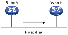
For example, in Figure 7, Router B performs traffic policing on packets from Router A and drops packets exceeding the limit. To avoid packet loss, you can perform traffic shaping on the outgoing interface of Router A so packets exceeding the limit are cached in Router A. Once resources are released, traffic shaping takes out the cached packets and sends them out.
|
|
NOTE: Traffic shaping supports shaping only the outbound traffic. |
Configuring traffic policing
The switch implements color-aware CAR in traffic policing. For information about the color-aware mode, see RFC 2697.
To configure traffic policing:
|
Step |
Command |
|
1. Enter system view. |
system-view |
|
2. Create a class and enter class view. |
traffic classifier tcl-name [ operator { and | or } ] |
|
3. Configure match criteria. |
if-match match-criteria |
|
4. Return to system view. |
quit |
|
5. Create a behavior and enter behavior view. |
traffic behavior behavior-name |
|
6. Configure a traffic policing action. |
car cir committed-information-rate [ cbs committed-burst-size [ ebs excess-burst-size ] ] [ pir peak-information-rate ] [ red action ] |
|
7. Return to system view. |
quit |
|
8. Create a policy and enter policy view. |
qos policy policy-name |
|
9. Associate the class with the traffic behavior in the QoS policy. |
classifier tcl-name behavior behavior-name |
|
10. Return to system view. |
quit |
|
11. Apply the QoS policy. |
· Applying the QoS policy to an interface · Applying the QoS policy to a VLAN |
Configuring GTS
|
IMPORTANT: · GTS for software forwarding does not support IPv6. · Do not configure GTS on a main interface and its subinterfaces at the same time. |
You can configure the following types of GTS:
· Queue-based GTS—configuring GTS parameters for packets of a certain queue.
· GTS for all traffic—configuring GTS parameters for all traffic.
Configuring queue-based GTS
|
Step |
Command |
Remarks |
|
1. Enter system view. |
system-view |
N/A |
|
2. Enter interface view or port group view. |
· Enter interface view: · Enter port group view: |
Use either command. Settings in interface view take effect on the current interface. Settings in port group view take effect on all ports in the port group. |
|
3. Configure GTS for a queue. |
qos gts queue queue-number cir committed-information-rate [ cbs committed-burst-size |
N/A |
Configuring GTS for all traffic
|
Step |
Command |
Remarks |
|
1. Enter system view. |
system-view |
N/A |
|
2. Enter interface view or port group view. |
· Enter interface view: · Enter port group view: |
Use either command. Settings in interface view take effect on the current interface. Settings in port group view take effect on all ports in the port group. |
|
3. Configure GTS on the interface or port group. |
qos gts any cir committed-information-rate [ cbs committed-burst-size ] |
N/A |
Displaying and maintaining traffic policing and GTS
|
Task |
Command |
Remarks |
|
Display CAR resources usage (in standalone mode). |
display car resource [ slot slot-number ] [ | { begin | exclude | include } regular-expression ] |
Available in any view. |
|
Display CAR resources usage (in IRF mode). |
display car resource [ chassis chassis-number slot slot-number ] [ | { begin | exclude | include } regular-expression ] |
Available in any view. |
|
Display interface GTS configuration information. |
display qos gts interface [ interface-type interface-number ] [ | { begin | exclude | include } regular-expression ] |
Available in any view. |
Overview
Causes, impacts, and countermeasures of congestion
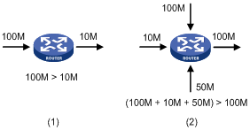
Congestion occurs on a link or node when traffic size exceeds the processing capability of the link or node. It is typical of a statistical multiplexing network and can be caused by link failures, insufficient resources, and various other causes. Figure 8 shows some common congestion scenarios:
Figure 8 Traffic congestion causes
Congestion can bring the following negative results:
· Increased delay and jitter during packet transmission
· Decreased network throughput and resource use efficiency
· Network resource (memory in particular) exhaustion and system breakdown
Congestion is unavoidable in switched networks or multi-user application environments. To improve the service performance of your network, you must take measures to manage and control it.
One major issue that congestion management deals with is how to define a resource dispatching policy to prioritize packets for forwarding when congestion occurs.
Congestion management policies
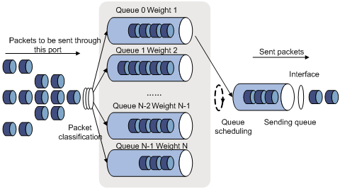
Queuing is a common congestion management technique. It classifies traffic into queues and picks out packets from each queue by using a certain algorithm. Various queuing algorithms are available, and each addresses a particular network traffic problem. Your choice of algorithm affects bandwidth assignment, delay, and jitter significantly.
Congestion management involves queue creating, traffic classification, packet enqueuing, and queue scheduling. Queue scheduling treats packets with different priorities differently to transmit high-priority packets preferentially.
This section briefly describes several common queue-scheduling mechanisms.
FIFO
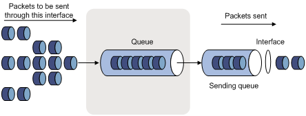
As shown in Figure 9, the first in first out (FIFO) uses a single queue and does not classify traffic or schedule queues. FIFO delivers packets depending on their arrival order, with the one arriving earlier scheduled first. The only concern of FIFO is queue length, which affects delay and packet loss rate. On a device, resources are assigned to packets depending on their arrival order and load status of the device. The best-effort service model uses FIFO queuing.
FIFO does not address congestion problems. If only one FIFO output/input queue exists on a port, you can hardly ensure timely delivery of mission-critical or delay-sensitive traffic or smooth traffic jitter. The situation gets worsened if malicious traffic is present to occupy bandwidth aggressively. To control congestion and prioritize forwarding of critical traffic, you must use other queue scheduling mechanisms, where multiple queues can be configured. Within each queue, however, FIFO is still used.
By default, FIFO queuing is used on interfaces.
Priority queuing
Figure 10 Priority queuing (PQ)
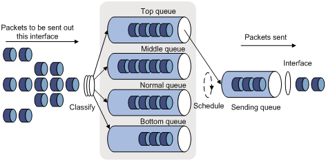
Priority queuing is designed for mission-critical applications. The key feature of mission-critical applications is that they require preferential service to reduce the response delay when congestion occurs. Priority queuing can flexibly determine the order of forwarding packets by network protocol (for example, IP and IPX), incoming interface, packet length, source/destination address, and so on. Priority queuing classifies packets into four queues: top, middle, normal, and bottom, in descending priority order. By default, packets are assigned to the normal queue. Each of the four queues is a FIFO queue.
Priority queuing schedules the four queues in the descending order of priority. It sends packets in the queue with the highest priority first. When the queue with the highest priority is empty, it sends packets in the queue with the second highest priority. In this way, you can assign the mission-critical packets to the high priority queue to make sure they are always served first. The common service packets are assigned to the low priority queues and transmitted when the high priority queues are empty.
The disadvantage of priority queuing is that packets in the lower priority queues cannot be transmitted if packets exist in the higher queues for a long time when congestion occurs.
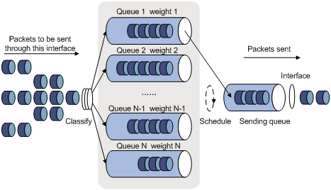
Weighted fair queuing
Figure 11 Weighted fair queuing (WFQ)
Before WFQ is introduced, make sure you have understood fair queuing (FQ). FQ is designed for fairly allocating network resources to reduce delay and jitter of each traffic flow as possible. In an attempt to balance the interests of all parties, FQ follows these principles:
· Different queues have fair dispatching opportunities for delay balancing among streams.
· Short packets and long packets are fairly scheduled: if long packets and short packets exist in queues, statistically the short packets should be scheduled preferentially to reduce the jitter between packets on the whole.
Compared with FQ, WFQ takes weights into account when determining the queue scheduling order. Statistically, WFQ gives high priority traffic more scheduling opportunities than low priority traffic. WFQ can automatically classify traffic according to the "session" information of traffic (protocol type, TCP or UDP source/destination port numbers, source/destination IP addresses, IP precedence bits in the ToS field, and so on), and try to provide as many queues as possible so that each traffic flow can be put into these queues to balance the delay of every traffic flow on a whole. When dequeuing packets, WFQ assigns the outgoing interface bandwidth to each traffic flow by precedence. The higher precedence value a traffic flow has, the more bandwidth it gets.
For example, assume that five flows exist in the current interface with precedence 0, 1, 2, 3, and 4. The total bandwidth quota is the sum of all the (precedence value + 1)s, 1 + 2 + 3 + 4 + 5 = 15.
The bandwidth percentage assigned to each flow is (precedence value of the flow + 1)/total bandwidth quota. The bandwidth percentages for flows are 1/15, 2/15, 3/15, 4/15, and 5/15.
Because WFQ can balance the delay and jitter of each flow when congestion occurs, it is suitable for handling some special occasions. For example, WFQ is used in the assured forwarding (AF) services of the Resource Reservation Protocol (RSVP). In Generic Traffic Shaping (GTS), WFQ schedules buffered packets.
The BE traffic enters queue 0, the AF traffic enters queues 1, 2, 3, and 4, the EF traffic enters queues 5 and 6, and the NC traffic enters queue 7. Queues of different types are scheduled by using SP, and queues of the same type are scheduled based on their weights.
CBQ
Only base cards support CBQ. Ethernet interface cards do not support CBQ.
Class-based queuing (CBQ) extends WFQ by supporting user-defined classes. When network congestion occurs, CBQ enqueues packets by user-defined traffic classification rules. Before that, congestion avoidance actions such as tail drop or weighted random early detection (WRED) and bandwidth restriction check are performed before packets are enqueued. When being dequeued, packets are scheduled by WFQ.
CBQ provides the following queues:
· An emergency queue, which enqueues emergent packets. The emergency queue is a FIFO queue without bandwidth restriction.
· Low Latency Queuing (LLQ), which is an EF queue. Because packets are fairly treated in CBQ, delay sensitive flows like video and voice packets might not be transmitted timely. To solve this problem, an EF queue was introduced to preferentially transmit delay sensitive flows. LLQ combines PQ and CBQ to preferentially transmit delay sensitive flows like voice packets. When defining traffic classes for LLQ, you can configure a class of packets to be preferentially transmitted. Such a class is called a "priority class". The packets of all priority classes are assigned to the same priority queue. Bandwidth restriction on each class of packets is checked before the packets are enqueued. During the dequeuing operation, packets in the priority queue are transmitted first. To reduce the delay of the other queues except the priority queue, LLQ assigns the maximum available bandwidth to each priority class. The bandwidth value polices traffic during congestion. When no congestion is present, a priority class can use more than the bandwidth assigned to it. During congestion, the packets of each priority class exceeding the assigned bandwidth are discarded.
· Bandwidth queuing (BQ), which is an AF queue. The BQ provides strict, exact, guaranteed bandwidth for AF traffic, and schedules the AF classes proportionally. The system supports up to 64 AF queues.
· Default queue, which is a WFQ queue. It transmits the BE traffic by using the remaining interface bandwidth.
The system matches packets with classification rules in the following order:
· Match packets with priority classes and then the other classes.
· Match packets with priority classes in the configuration order.
· Match packets with other classes in the configuration order.
· Match packets with classification rules in a class in the configuration order.
Congestion management technique comparison
Breaking through the single congestion management policy of FIFO for traditional IP devices, the current device provides all the congestion management techniques above mentioned to offer powerful QoS capabilities, meeting different QoS requirements of different applications.
Table 1 Congestion management technique comparison
|
Type |
Number of queues |
Advantages |
Disadvantages |
|
FIFO |
1 |
· No need to configure, easy to use · Easy to operate, low delay |
· All packets are treated equally. The available bandwidth, delay and drop probability are determined by the arrival order of packets. · No restriction on traffic from connectionless protocols (protocols without any flow control mechanism, UDP for example), resulting in bandwidth loss for traffic of connection-oriented protocols (TCP, for example). · No delay guarantee for time-sensitive real-time applications, such as VoIP |
|
PQ |
4 |
Absolute bandwidth and delay guarantees for real-time and mission critical applications such as VoIP |
· Need to configure; low processing speed · If no restriction is imposed on bandwidth assigned to high-priority packets, low-priority packets might fail to get bandwidth. |
|
WFQ |
Configurable |
· Easy to configure · Bandwidth guarantee for packets from cooperative (interactive) sources (such as TCP packets) · Reduced jitter · Reduced delay for interactive applications with a small amount of data · Bandwidth assignment based on traffic priority · Automatic bandwidth reassignment to increase bandwidth for each class when the number of traffic classes decreases |
The processing speed is faster than that of PQ and CQ but slower than that of FIFO |
|
CBQ |
Configurable (0 to 4) |
· Flexible traffic classification based on various rules and differentiated queue scheduling mechanisms for expedited forwarding (EF), assured forwarding (AF) and best-effort (BE) services. · Highly precise bandwidth guarantee and queue scheduling on the basis of AF service weights for various AF services · Absolutely preferential queue scheduling for the EF service to meet the delay requirement of real-time data; overcoming the disadvantage of PQ that some low-priority queues are not serviced by restricting the high-priority traffic · WFQ scheduling for best-effort traffic (the default class). |
The system overheads are large. |
|
|
NOTE: If the burst traffic is too heavy, increase the queue length to make queue scheduling more accurate. |
Configuring WFQ
Configuration procedure
On an interface without WFQ configured, the qos wfq command can enable WFQ and configure WFQ-related parameters. If WFQ is configured for the interface, the qos wfq command can modify the WFQ-related parameters.
To configure WFQ:
|
Step |
Command |
Remarks |
|
1. Enter system view. |
system-view |
N/A |
|
2. Enter interface view. |
interface interface-type interface-number |
N/A |
|
3. Configure WFQ. |
qos wfq queue weight schedule-value |
FIFO applies by default. |
|
4. Display interface WFQ configuration information. |
display qos wfq interface [ interface-type interface-number ] [ | { begin | exclude | include } regular-expression ] |
Optional. Available in any view. |
WFQ configuration example
Network requirements
Configure the weights of queues 2, 3, and 4 as 5, 10, and 20.
Configuration procedure
# Enter system view.
<Sysname> system-view
# Configure WFQ on interface POS 3/1/1.
[Sysname] interface Pos 3/1/1
[Sysname-Pos3/1/1] qos wfq 2 weight 5
[Sysname-Pos3/1/1] qos wfq 3 weight 10
[Sysname-Pos3/1/1] qos wfq 4 weight 20
Configuring CBQ
To configured CBQ:
1. Create a class and define a set of traffic match criteria in class view.
2. Create a traffic behavior, and define a group of QoS features in traffic behavior view.
3. Create a policy, and associate a traffic behavior with a class in policy view.
4. Apply the QoS policy in the interface view.
Defining a class
To define a class, create the class first and then configure match criteria in class view.
To define a class:
|
Step |
Command |
Remarks |
|
1. Enter system view. |
system-view |
N/A |
|
2. Create a class and enter class view. |
traffic classifier tcl-name [ operator { and | or } ] |
By default, the and keyword is used, and the relation between match criteria is logical AND. |
|
3. Configure match criteria. |
if-match match-criteria |
N/A |
|
|
NOTE: You must configure a default class to match any traffic and place the class-behavior association at the last of the policy, so that the traffic except EF and AF traffic can enter the BE queue (the default queue). |
Defining a traffic behavior
To define a traffic behavior, create the traffic behavior first and then configure QoS attributes in traffic behavior view.
Configuring AF and the minimum guaranteed bandwidth
When you configure AF and the minimum guaranteed bandwidth, follow these guidelines:
· You can apply this traffic behavior only to the outgoing traffic of an interface.
· You cannot configure the queue af command together with the queue ef or queue wfq command in the same traffic behavior.
· To reference both the queue ef command and the queue af command in a policy, you must configure them in the same unit (either bandwidth or percentage). If not, your referencing attempts will fail.
· The minimum guaranteed bandwidth specifies the bandwidth that is guaranteed for traffic, regardless of congestion on the interface. The AF traffic exceeding the minimum guaranteed bandwidth and the BE traffic compete for bandwidth. How much of the exceeding AF traffic can be forwarded depends on the congestion conditions on the interface.
To configure AF and the minimum guaranteed bandwidth:
|
Step |
Command |
|
1. Enter system view. |
system-view |
|
2. Create a traffic behavior and enter traffic behavior view. |
traffic behavior behavior-name |
|
3. Configure AF and the minimum guaranteed bandwidth. |
queue af bandwidth bandwidth |
Configuring EF and the maximum bandwidth
When you configure EF and the maximum bandwidth, follow these guidelines:
· You cannot configure the queue ef command together with the any of the commands queue af, queue wfq, and wred for a traffic behavior.
· You can apply this behavior to only the outgoing traffic of an interface.
· The value range for the bandwidth argument is 64 to 10000000 kbps. The value range for the burst argument is 1600 to 1000000000 bytes, and the default is 25 × bandwidth.
· The maximum bandwidth specifies the maximum bandwidth allocated to the EF traffic, regardless of congestion on the interface. The forwarding for the EF traffic exceeding the maximum bandwidth depends on the congestion conditions on the interface.
· To reference both the queue ef command and the queue af command in a policy, you must configure them in the same unit (either bandwidth or percentage). If not, your referencing attempts will fail.
To configure EF and the maximum bandwidth:
|
Step |
Command |
|
1. Enter system view. |
system-view |
|
2. Create a traffic behavior and enter traffic behavior view. |
traffic behavior behavior-name |
|
3. Configure EF and the maximum bandwidth. |
queue ef bandwidth bandwidth [ cbs burst ] |
Configuring WFQ
|
Step |
Command |
|
1. Enter system view. |
system-view |
|
2. Create a traffic behavior and enter traffic behavior view. |
traffic behavior behavior-name |
|
3. Configure WFQ. |
queue wfq |
|
|
NOTE: · You can associate the traffic behavior that contains a WFQ action only with the default class. · You cannot use the queue wfq command together with the queue ef or queue af command for the same traffic behavior. · You can apply the traffic behavior to only the outgoing traffic of an interface. |
Using WRED drop
|
Step |
Command |
Remarks |
|
1. Enter system view. |
system-view |
N/A |
|
2. Create a traffic behavior and enter traffic behavior view. |
traffic behavior behavior-name |
N/A |
|
3. Use WRED drop. |
wred [ dscp | ip-precedence ] |
· dscp: Uses the DSCP value for calculating the drop probability for a packet. · ip-precedence: Uses the IP precedence value for calculating the drop probability for a packet. This keyword is used by default. |
|
|
NOTE: · Before configuring the wred [ dscp | ip-precedence ] command, configure the queue af command or the queue wfq command. · When the WRED drop configuration is removed, other configurations under it are deleted. · The WRED configuration in QoS policies overrides the WRED configuration directly configured on interfaces. |
Defining a QoS policy
To associate a traffic behavior with a specific class in policy view:
|
Step |
Command |
|
1. Enter system view. |
system-view |
|
2. Create a policy and enter policy view. |
qos policy policy-name |
|
3. Associate a traffic behavior with a class in the policy. |
classifier tcl-name behavior behavior-name |
Applying the QoS policy
Use the qos apply policy command to apply a policy to a physical interface. You can apply a policy to multiple physical interfaces.
To apply a policy to an interface:
|
Step |
Command |
Remarks |
|
1. Enter system view. |
system-view |
N/A |
|
2. Enter interface view or port group view. |
· Enter interface view: · Enter port group view: |
Use either command. Settings in interface view take effect on the current interface. Settings in port group view take effect on all ports in the port group. |
|
3. Apply a policy to the interface. |
qos apply policy policy-name { inbound | outbound } |
N/A |
|
|
NOTE: · You can apply a QoS policy configured with various QoS actions (including remark, car, queue af, queue ef, queue wfq, wred, and so on) to common physical interfaces. · An inbound QoS policy cannot contain any of these queuing actions: queue ef, queue af, or queue wfq. |
Displaying and maintaining CBQ
|
Task |
Command |
Remarks |
|
display traffic classifier user-defined [ tcl-name ] [ | { begin | exclude | include } regular-expression ] |
Available in any view. |
|
|
Display traffic behavior configuration information. |
display traffic behavior user-defined [ behavior-name ] [ | { begin | exclude | include } regular-expression ] |
Available in any view. |
|
Display QoS policy configuration information. |
display qos policy user-defined [ policy-name [ classifier tcl-name ] ] [ | { begin | exclude | include } regular-expression ] |
Available in any view. |
|
Display interface QoS policy configuration information. |
display qos policy interface [ interface-type interface-number ] [ inbound | outbound ] [ | { begin | exclude | include } regular-expression ] |
Available in any view. |
CBQ configuration example
Network requirements
As shown in Figure 12, configure a QoS policy to meet the following requirements:
· Traffic from Switch C is classified into three classes based on DSCP values; perform AF for traffic with the DSCP values AF11 and AF21 and set the guaranteed bandwidth to 5 Mbps.
· Perform EF for traffic with the DSCP value EF and set the guaranteed bandwidth to 30 Mbps.
Before performing the configuration, make sure:
· Switch C can reach Switch D through Switch A and Switch B.
· The DSCP fields have been set for the traffic before the traffic enters Switch A.

Configuration procedure
1. Configure Switch A:
# Define three classes to match the IP packets with the DSCP values AF11, AF21 and EF.
<SwitchA> system-view
[SwitchA] traffic classifier ef_class
[SwitchA-classifier-ef_class] if-match dscp ef
[SwitchA-classifier-ef_class] quit
[SwitchA] traffic classifier af11_class
[SwitchA-classifier-af11_class] if-match dscp af11
[SwitchA-classifier-af11_class] quit
[SwitchA]traffic classifier af21_class
[SwitchA-classifier-af21_class] if-match dscp af21
[SwitchA-classifier-af21_class] quit
# Define a default class named be_class to match all IP packets.
[SwitchA] acl number 3000
[SwitchA] rule 0 permit ip
[SwitchA] traffic classifier be_class
[SwitchA-classifier-be_class] if-match acl 3000
[SwitchA-classifier-be_class] quit
# Define a traffic behavior named ef_behav, configure EF in the behavior, and set the guaranteed bandwidth to 30720 kbps.
[SwitchA] traffic behavior ef_behav
[SwitchA-behavior-ef_behav] queue ef bandwidth 30720
[SwitchA-behavior-ef_behav] quit
# Define a traffic behavior af11_behav, configure AF in the traffic behavior, and set the guaranteed bandwidth to 5120 kbps. Configure traffic behavior af21_behav in a similar way.
[SwitchA] traffic behavior af11_behav
[SwitchA-behavior-af11_behav] queue af bandwidth 5120
[SwitchA-behavior-af11_behav] quit
[SwitchA] traffic behavior af21_behav
[SwitchA-behavior-af21_behav] queue af bandwidth 5120
[SwitchA-behavior-af21_behav] quit
# Define a traffic behavior named be_behav, configure WFQ in the traffic behavior, and configure the drop mode as WRED.
[SwitchA] traffic behavior be_behav
[SwitchA-behavior-be_behav] queue wfq
[SwitchA-behavior-be_behav] wred
[SwitchA-behavior-be_behav] quit
# Create a QoS policy named dscp, and associate the defined classes with the corresponding behaviors as needed.
[SwitchA] qos policy dscp
[SwitchA-qospolicy-dscp] classifier ef_class behavior ef_behav
[SwitchA-qospolicy-dscp] classifier af11_class behavior af11_behav
[SwitchA-qospolicy-dscp] classifier af21_class behavior af21_behav
[SwitchA-qospolicy-dscp] classifier be_class behavior be_behav
[SwitchA-qospolicy-dscp] quit
# Define a flow template named dscp, and apply it to interface POS 3/1/1.
[SwitchA]flow-template dscp basic dscp ethernet-protocol
[SwitchA]interface Pos3/1/1
[SwitchA-Pos3/1/1] flow-template dscp
# Apply QoS policy dscp to the outgoing traffic of interface POS 3/1/1.
[SwitchA-Pos3/1/1] qos apply policy dscp outbound
[SwitchA-Pos3/1/1] quit
# After the configuration, display the QoS policy configuration on interface POS 3/1/1 to verify the configuration.
[SwitchA] display qos policy interface Pos 3/1/1 outbound
Interface: Pos3/1/1
Direction: Outbound
Policy: dscp
Classifier: ef_class
Operator: AND
Rule(s) : If-match dscp ef
Behavior: ef_behav
Expedited Forwarding:
Bandwidth 30720 (Kbps), CBS 768000 (Bytes)
Matched : 100/6400 (Packets/Bytes)
Enqueued : 100/6400 (Packets/Bytes)
Discarded: 0/0 (Packets/Bytes)
Classifier: af11_class
Operator: AND
Rule(s) : If-match dscp af11
Behavior: af11_behav
Assured Forwarding:
Bandwidth 5120 (Kbps)
Matched : 50/3200 (Packets/Bytes)
Enqueued : 50/3200 (Packets/Bytes)
Discarded: 0/0 (Packets/Bytes)
Classifier: af21_class
Operator: AND
Rule(s) : If-match dscp af21
Behavior: af21_behav
Assured Forwarding:
Bandwidth 5120 (Kbps)
Matched : 50/3200 (Packets/Bytes)
Enqueued : 50/3200 (Packets/Bytes)
Discarded: 0/0 (Packets/Bytes)
Classifier: be_class
Operator: AND
Rule(s) : If-match acl 3000
Behavior: be_behav
Flow Based Weighted Fair Queuing
Matched : 1000/128000 (Packets/Bytes)
Discard Method: IP Precedence based WRED
Overview
Causes, impacts, and countermeasures
Network congestion degrades service quality on a traditional network. Congestion is a situation where the forwarding rate decreases due to insufficient resources, resulting in extra delay.
Congestion is more likely to occur in complex packet switching circumstances. Figure 13 shows two common cases:
Figure 13 Traffic congestion causes
Congestion can bring the following negative results:
· Increased delay and jitter during packet transmission
· Decreased network throughput and resource use efficiency
· Network resource (memory in particular) exhaustion and even system breakdown
Congestion is unavoidable in switched networks and multi-user application environments. To improve the service performance of your network, you must take some proper measures to address the congestion issues.
The key to congestion management is how to define a dispatching policy for resources to decide the order of forwarding packets when congestion occurs.
Congestion management techniques
Congestion management uses queuing and scheduling algorithms to classify and sort traffic leaving a port. Each queuing algorithm addresses a particular network traffic problem, and has a different impact on bandwidth resource assignment, delay, and jitter.
Queue scheduling processes packets by their priorities, preferentially forwarding high-priority packets. This section describes in detail Strict Priority (SP) queuing, Weighted Round Robin (WRR) queuing, Weighted Fair Queuing (WFQ), and Class-Based Queuing (CBQ).
SP queuing
SP queuing is designed for mission-critical applications, which require preferential service to reduce the response delay when congestion occurs.
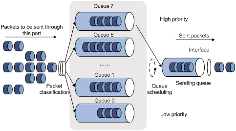
As shown in Figure 14, SP queuing classifies eight queues on a port into eight classes, numbered 7 to 0 in descending priority order.
SP queuing schedules the eight queues in the descending order of priority. It sends packets in the queue with the highest priority first. When the queue with the highest priority is empty, it sends packets in the queue with the second highest priority, and so on. You can assign mission-critical packets to the high priority queue to make sure they are always served first and common service packets to the low priority queues and transmitted when the high priority queues are empty.
The disadvantage of SP queuing is that packets in the lower priority queues cannot be transmitted if packets exist in the higher priority queues. This might cause lower priority traffic to starve to death.
WRR queuing
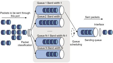
WRR queuing schedules all the queues in turn to make sure every queue is be served for a certain time, as shown in Figure 15.
Assume a port provides eight output queues. WRR assigns each queue a weight value (represented by w7, w6, w5, w4, w3, w2, w1, or w0) to decide the proportion of resources assigned to the queue. On a 100 Mbps port, you can configure the weight values of WRR queuing to 50, 30, 10, 10, 50, 30, 10, and 10 (corresponding to w7, w6, w5, w4, w3, w2, w1, and w0). In this way, the queue with the lowest priority can get a minimum of 5 Mbps of bandwidth. WRR avoids the disadvantage of SP queuing that packets in low-priority queues might fail to be served for a long time.
Another advantage of WRR queuing is that when the queues are scheduled in turn, the service time for each queue is not fixed. If a queue is empty, the next queue will be scheduled immediately. This improves bandwidth resource use efficiency.
WRR queuing includes the following types:
· Basic WRR queuing—Contains multiple queues. You can configure the weight, percentage (or byte count) for each queue and WRR schedules these queues based on the user-defined parameters in a round robin manner.
· Group-based WRR queuing—All the queues are scheduled by WRR. You can assign the output queues to WRR priority queue group 1 and WRR priority queue group 2. Round robin queue scheduling is performed for the group which has the highest-numbered queue. If the group is empty, round robin queue scheduling is performed for the other group.
WFQ queuing
Figure 16 WFQ queuing
WFQ is similar to WRR. They both support scheduling weights in queue length. The difference is that WFQ enables you to set guaranteed bandwidth that a WFQ queue can get during congestion.
CBQ
CBQ provides one FIFO queue for each user-defined class to buffer traffic of the class. When the network is congested, CBQ classifies packets into user-defined classes, and assigns different classes of packets to different queues after performing congestion avoidance and bandwidth restriction check. When dequeuing packets, CBQ schedules packets from queues in proportion to their weights.
CBQ provides the following queuing types:
· Low latency queuing (LLQ)—LLQ queues are EF queues, and ensure strict priority service for real-time traffic. CBQ always schedules traffic in LLQ queues preferentially. To guarantee that other queues can get served when congestion occurs, you can set the maximum bandwidth for each LLQ queue. In normal cases, an LLQ queue can use more bandwidth than allocated. When congestion occurs, the exceeding traffic is dropped. You can also configure a burst size for LLQ queues.
· Bandwidth queuing (BQ)—BQ queues are AF queues. BQ provides strict, exact, guaranteed bandwidth for AF traffic, and schedules the AF classes proportionally.
· WFQ—One WFQ queue is available for BE traffic, and uses the remaining bandwidth to send the BE traffic.
BQ and WFQ use tail drop by default. You can configure a weighted random early detection (WRED) drop policy to limit traffic.
Hardware congestion management configuration approaches
To configure hardware congestion management, you can use one of the following methods:
· Configure queue scheduling for each queue in interface view or port group view.
· Configure a queue scheduling profile, as described in hardware congestion management with queue scheduling profiles.
· Configure queue scheduling in a QoS policy, as described in Configuring CBQ.
Complete the following tasks to achieve hardware congestion management:
|
Task |
Remarks |
|
Configuring per-queue hardware congestion management: |
Optional. |
|
Optional. |
|
|
Optional. |
Configuring per-queue hardware congestion management
Configuring SP queuing
|
Step |
Command |
Remarks |
|
1. Enter system view. |
system-view |
N/A |
|
2. Enter interface view or port group view. |
· Enter interface view: · Enter port group view: |
Use either command. Settings in interface view take effect on the current interface. Settings in port group view take effect on all ports in the port group. |
|
3. Configure SP queuing. |
qos sp |
The default queuing algorithm on an interface is SP queuing. |
|
4. Display SP queuing configuration. |
display qos sp interface [ interface-type interface-number ] [ | { begin | exclude | include } regular-expression ] |
Optional. Available in any view. |
Configuration example
1. Network requirements
Configure GigabitEthernet 3/0/1 to use SP queuing.
2. Configuration procedure
# Enter system view
<Sysname> system-view
# Configure GigabitEthernet 3/0/1 to use SP queuing.
[Sysname] interface GigabitEthernet 3/0/1
[Sysname-GigabitEthernet3/0/1] qos sp
Configuring WFQ queuing
Configuration procedure
To configure a WFQ queue:
|
Step |
Command |
Remarks |
|
1. Enter system view. |
system-view |
N/A |
|
2. Enter interface view or port group view. |
· Enter interface view: · Enter port group view: |
Use either command. Settings in interface view take effect on the current interface. Settings in port group view take effect on all ports in the port group. |
|
3. Enable WFQ queuing. |
qos wfq |
After WFQ queuing is enabled, all queues of an interface are scheduled by WFQ, and have a default scheduling weight of 1 and a default minimum guaranteed bandwidth of 40 kbps. |
|
4. Specify a scheduling weight for a WFQ queue. |
qos wfq queue-id weight schedule-value |
Optional. |
|
5. Configure the minimum guaranteed bandwidth for a WFQ queue. |
qos bandwidth queue queue-id min bandwidth-value |
Optional. |
|
6. Display WFQ queuing configuration. |
display qos wfq interface [ interface-type interface-number ] [ | { begin | exclude | include } regular-expression ] |
Optional. Available in any view. |
Configuration example
1. Network requirements
Assign the scheduling weights 1, 5, 10, 20, and 10 to WFQ queues 1, 3, 4, 5, and 6, respectively.
2. Configuration procedure
# Enter system view.
<Sysname> system-view
# Configure WFQ queues on GigabitEthernet 3/0/1.
[Sysname] interface GigabitEthernet 3/0/1
[Sysname-GigabitEthernet3/0/1] qos wfq
[Sysname-GigabitEthernet3/0/1] qos wfq 1 weight 1
[Sysname-GigabitEthernet3/0/1] qos wfq 3 weight 5
[Sysname-GigabitEthernet3/0/1] qos wfq 4 weight 10
[Sysname-GigabitEthernet3/0/1] qos wfq 5 weight 20
[Sysname-GigabitEthernet3/0/1] qos wfq 6 weight 10
Configuring WFQ queuing
|
|
IMPORTANT: This feature is available on only the POS subcards. |
With a WFQ queue configured, an interface has WFQ enabled. Other queues on the interface use the default WFQ scheduling value 1.
Configuration procedure
To configure a WFQ queue:
|
Step |
Command |
Remarks |
|
1. Enter system view. |
system-view |
N/A |
|
2. Enter interface view or port group view. |
· Enter interface view: · Enter port group view: |
Use either command. Settings in interface view take effect on the current interface. Settings in port group view take effect on all ports in the port group. |
|
3. Configure a queue as a WFQ queue and specify a scheduling weight for the queue. |
qos wfq queue-id weight schedule-value |
When you configure this command for a queue on a port, this command configures all the other queues as WFQ queues on the port, and assigns the scheduling weight 1 to the queues which are not WFQ queues previously. |
|
4. Configure the minimum guaranteed bandwidth for a WFQ queue. |
qos bandwidth queue queue-id min bandwidth-value |
Optional. |
|
5. Display WFQ queuing configuration. |
display qos wfq interface [ interface-type interface-number ] [ | { begin | exclude | include } regular-expression ] |
Optional. Available in any view. |
Configuration example
1. Network requirements
Assign the scheduling weight 1, 5, 10, 20, and 10 to WFQ queues 1, 3, 4, 5, and 6.
2. Configuration procedure
# Enter system view.
<Sysname> system-view
# Configure WFQ queues on POS 3/1/1.
[Sysname] interface POS 3/1/1
[Sysname-Pos3/1/1] qos wfq 1 weight 1
[Sysname-Pos3/1/1] qos wfq 3 weight 5
[Sysname-Pos3/1/1] qos wfq 4 weight 10
[Sysname-Pos3/1/1] qos wfq 5 weight 20
[Sysname-Pos3/1/1] qos wfq 6 weight 10
Configuring hardware congestion management with queue scheduling profiles
Introduction to queue scheduling profile
In a queue scheduling profile, you can configure scheduling parameters for each queue. By applying the queue scheduling profile to an interface, you can implement congestion management on the interface. You can modify the scheduling parameters in a queue scheduling profile already applied to an interface.
Queue scheduling profiles support the following queue scheduling algorithms: SP and WRR. In a queue scheduling profile, you can configure either of the two queue scheduling algorithms or a mix of them. When both scheduling algorithms are configured, SP queues and WRR groups are scheduled in the descending order of queue ID. In a WRR priority group, queues are scheduled based on their weights. If SP and WRR are configured in a queue scheduling profile, the scheduling order is as shown in Figure 17.
Figure 17 Queue scheduling profile configured with both SP and WRR
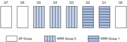
· Queue 7 is of the highest priority. Its packets are sent preferentially.
· Queue 6 is of second highest priority. Packets in queue 6 are sent when queue 7 is empty.
· Queue 3, queue 4, and queue 5 are scheduled according to their weights. When both queue 6 and queue 7 are empty, WRR group 0 is scheduled.
· Queue 1 and queue 2 are scheduled according to their weights. WRR group 1 is scheduled when queue 7, queue 6, queue 5, queue 4, and queue 3 are all empty.
· Queue 0 is of the lowest priority, and it is scheduled when all the other queues are empty.
Configuring a queue scheduling profile
To configure a queue scheduling profile, create the queue scheduling profile first, and then enter the queue scheduling profile view to configure its queue scheduling parameters. At last, apply the queue scheduling profile to the specified interface.
To configure a queue scheduling profile:
|
Step |
Command |
Remarks |
|
1. Enter system view. |
system-view |
N/A |
|
2. Create a queue scheduling profile and enter queue scheduling profile view. |
qos qmprofile profile-name |
N/A |
|
3. Configure queue scheduling parameters. |
· Configure a queue to use SP: · Configure a queue to use WRR: |
One queue can use only one queue scheduling algorithm. In a queue scheduling profile, you can configure different queue scheduling algorithms for different queues. By default, each queue uses the SP queue scheduling. |
|
4. Return to system view. |
quit |
N/A |
|
5. Enter interface view or port group view. |
· Enter interface view: · Enter port group view: |
Use either command. Configured in interface view, the setting takes effect on the current interface only. Configured in port group view, the setting takes effect on all ports in the port group. |
|
6. Apply the queue scheduling profile to the interface or port group. |
qos apply qmprofile profile-name |
N/A |
|
|
IMPORTANT: · Only one queue scheduling profile can be applied to an interface. · To guarantee accurate scheduling, make sure the queues in a WRR group have consecutive numbers. |
Displaying and maintaining queue scheduling profiles
|
Task |
Command |
Remarks |
|
Display the configuration of the specified or all queue scheduling profiles. |
display qos qmprofile configuration [ profile-name ] [ | { begin | exclude | include } regular-expression ] |
Available in any view. |
|
Display the queue scheduling profiles already applied to interfaces. |
display qos qmprofile interface [ interface-type interface-number ] [ | { begin | exclude | include } regular-expression ] |
Available in any view. |
Queue scheduling profile configuration example
Network requirements
Configure a queue scheduling profile to meet the following requirements on interface GigabitEthernet 3/0/1:
· Queue 7 is of the highest priority, and its packets are sent preferentially.
· Queue 4, queue 5, and queue 6 are in WRR group 1 and scheduled according to their weights, which are 1, 5, and 10. When queue 7 is empty, WRR group 0 is scheduled.
· Queue 1, queue 2, and queue 3 are in WRR group 2 and scheduled according to their weights, which are 1, 10, and 20. When queue 4, queue 5, queue 6, and queue 7 are all empty, WRR group 1 is scheduled.
· Queue 0 is of the lowest priority. Queue 0 is scheduled when all the other queues are empty.
Configuration procedure
# Enter system view.
<Sysname> system-view
# Create queue scheduling profile qm1.
[Sysname] qos qmprofile qm1
[Sysname-qmprofile-qm1]
# Configure queue 7 to use SP queuing.
[Sysname-qmprofile-qm1] queue 7 sp
# Assign queue 4, queue 5, and queue 6 to WRR group 0, with the weight of 1, 5, and 10.
[Sysname-qmprofile-qm1] queue 4 wrr group 1 weight 1
[Sysname-qmprofile-qm1] queue 5 wrr group 1 weight 5
[Sysname-qmprofile-qm1] queue 6 wrr group 1 weight 10
# Assign queue 1, queue 2, and queue 3 to WRR group 1, with the weight of 1, 10, and 20.
[Sysname-qmprofile-qm1] queue 1 wrr group 2 weight 1
[Sysname-qmprofile-qm1] queue 2 wrr group 2 weight 10
[Sysname-qmprofile-qm1] queue 3 wrr group 2 weight 20
# Configure queue 0 to use SP queuing.
[Sysname-qmprofile-qm1] queue 0 sp
[Sysname-qmprofile-qm1] quit
# Apply queue scheduling profile qm1 to interface GigabitEthernet 3/0/1.
[Sysname] interface gigabitethernet 3/0/1
[Sysname-GigabitEthernet3/0/1] qos apply qmprofile qm1
After the configuration is completed, interface GigabitEthernet 3/0/1 performs queue scheduling as specified in queue scheduling profile qm1.
Configuring CBQ
CBQ is implemented through QoS policies.
When matching a packet against a QoS policy, the system:
· Matches the packet against class-behavior associations in the order they are configured.
· Matches the packet against the criteria in each class in the order they are configured.
CBQ configuration task list
Complete these tasks to configured CBQ:
Defining a class
|
Step |
Command |
Remarks |
|
1. Enter system view. |
system-view |
N/A |
|
2. Create a class and enter class view. |
traffic classifier tcl-name [ operator { and | or } ] |
By default, the and keyword is used, and the relation between match criteria is logical AND. |
|
3. Configure match criteria. |
if-match match-criteria |
N/A |
|
|
NOTE: You must configure a default class to match any traffic and place the class-behavior association at the last of the policy, so that the traffic except EF and AF traffic can enter the BE queue (the default queue). |
Defining a traffic behavior
Configuring AF and the minimum guaranteed bandwidth
When you configure AF and the minimum guaranteed bandwidth, follow these guidelines:
· You cannot configure the queue af command together with the queue ef or queue wfq command in the same traffic behavior.
· You can apply this traffic behavior only to the outgoing traffic of an interface.
· The minimum guaranteed bandwidth specifies the bandwidth that is guaranteed for traffic, regardless of congestion on the interface. The AF traffic exceeding the minimum guaranteed bandwidth and the BE traffic compete for bandwidth. How much of the exceeding AF traffic can be forwarded depends on the congestion conditions on the interface.
To configure AF and the minimum guaranteed bandwidth:
|
Step |
Command |
|
1. Enter system view. |
system-view |
|
2. Create a traffic behavior and enter traffic behavior view. |
traffic behavior behavior-name |
|
3. Configure AF and the minimum guaranteed bandwidth. |
queue af bandwidth bandwidth |
Configuring EF and the maximum bandwidth
When you configure EF and the maximum bandwidth, follow these guidelines:
· You cannot configure the queue ef command together with the any of the commands queue af, queue wfq, and wred for a traffic behavior.
· You can apply this behavior to only the outgoing traffic of an interface.
· The value range for the bandwidth argument is 64 to 10000000 kbps. The value range for the burst argument is 1600 to 1000000000 bytes, and the default is 25 × bandwidth.
· The maximum bandwidth specifies the maximum bandwidth allocated to the EF traffic, regardless of congestion on the interface. The forwarding for the EF traffic exceeding the maximum bandwidth depends on the congestion conditions on the interface.
To configure EF and the maximum bandwidth:
|
Step |
Command |
|
1. Enter system view. |
system-view |
|
2. Create a traffic behavior and enter traffic behavior view. |
traffic behavior behavior-name |
|
3. Configure EF and the maximum bandwidth. |
queue ef bandwidth bandwidth [ cbs burst ] |
Configuring WFQ
|
Step |
Command |
|
1. Enter system view. |
system-view |
|
2. Create a traffic behavior and enter traffic behavior view. |
traffic behavior behavior-name |
|
3. Configure WFQ. |
queue wfq |
|
|
NOTE: · You cannot use the queue wfq command together with the queue ef or queue af command for the same traffic behavior. · You can apply the traffic behavior to only the outgoing traffic of an interface. |
Configuring a WRED drop action
|
Step |
Command |
Remarks |
|
1. Enter system view. |
system-view |
N/A |
|
2. Create a traffic behavior and enter traffic behavior view. |
traffic behavior behavior-name |
N/A |
|
3. Configure a WRED drop action. |
wred [ dscp | ip-precedence ] |
· dscp: Uses the DSCP value for calculating the drop probability for a packet. · ip-precedence: Uses the IP precedence value for calculating the drop probability for a packet. This keyword is used by default. |
|
|
NOTE: · You cannot use the wred command together with the queue ef command in the same behavior. · You can configure the wred [ dscp | ip-precedence ] command only after you configure the queue af command or the queue wfq command. · You can apply the behavior to only the outgoing traffic of an interface. |
Defining a QoS policy
To associate a traffic behavior with a specific class in policy view:
|
Step |
Command |
|
1. Enter system view. |
system-view |
|
2. Create a policy and enter policy view. |
qos policy policy-name |
|
3. Associate a traffic behavior with a class in the policy. |
classifier tcl-name behavior behavior-name |
Applying the QoS policy
You can apply a policy to multiple physical interfaces or subinterfaces.
Configuration restrictions and guidelines
When you apply a QoS policy, follow these guidelines:
· Depending on the match criteria configured in a class of a QoS policy, you might need to apply a flow template to an interface before applying the QoS policy to the interface.
· You can apply a QoS policy containing a CBQ action only to the outgoing traffic of an interface.
· The QoS policy applied to the outgoing traffic on an interface does not regulate local packets. Local packets refer to the critical protocol packets sent by the local system for maintaining the normal operation of the device. To avoid drop of local packets, QoS does not process them. Commonly used local packets include link maintenance packets, IS-IS packets, OSPF packets, RIP packets, BGP packets, LDP packets, RSVP packets, and SSH packets.
· You cannot apply a QoS policy containing a CBQ action to an RPR interface.
· You cannot apply a QoS policy containing a CBQ action only to an interface.
· To guarantee that a QoS policy containing a CBQ action works properly, H3C recommends not configuring a GTS action or any of the queuing features (queue ef, queue af, and queue wfq) in the QoS policy.
· In a QoS policy, make sure the sum of bandwidth assigned to EF queues, AF queues, and BE queues does not exceed the actual bandwidth of the target interface. Otherwise, CBQ does not work as expected.
Configuration procedure
To apply a CBQ policy to a physical interface:
|
Step |
Command |
Remarks |
|
1. Enter system view. |
system-view |
N/A |
|
2. Enter interface view or port group view. |
· Enter interface view: · Enter port group view: |
Use either command. Settings in interface view take effect on the current interface. Settings in port group view take effect on all ports in the port group. |
|
3. Apply a policy to the interface. |
qos apply policy policy-name { inbound | outbound } |
N/A |
Displaying and maintaining CBQ
|
Task |
Command |
Remarks |
|
Display class configuration information. |
display traffic classifier user-defined [ tcl-name ] [ | { begin | exclude | include } regular-expression ] |
Available in any view. |
|
Display traffic behavior configuration information. |
display traffic behavior user-defined [ behavior-name ] [ | { begin | exclude | include } regular-expression ] |
Available in any view. |
|
Display QoS policy configuration information. |
display qos policy user-defined [ policy-name [ classifier tcl-name ] ] [ | { begin | exclude | include } regular-expression ] |
Available in any view. |
|
Display interface QoS policy configuration information. |
display qos policy interface [ interface-type interface-number ] [ inbound | outbound ] [ | { begin | exclude | include } regular-expression ] |
Available in any view. |
CBQ configuration example
Network requirements
As shown in Figure 18, configure a QoS policy to meet the following requirements:
· Traffic from Switch C is classified into three classes based on DSCP values; perform AF for traffic with the DSCP values AF11 and AF21 and set the guaranteed bandwidth to 5 Mbps.
· Perform EF for traffic with the DSCP value EF and set the guaranteed bandwidth to 30 Mbps.
Before performing the configuration, make sure:
· Switch C can reach Switch D through Switch A and Switch B.
· The DSCP fields have been set for the traffic before the traffic enters Switch A.
Configuration procedure
1. Configure Switch A:
# Define three classes to match the IP packets with the DSCP values AF11, AF21 and EF.
<SwitchA> system-view
[SwitchA] traffic classifier ef_class
[SwitchA-classifier-ef_class] if-match dscp ef
[SwitchA-classifier-ef_class] quit
[SwitchA] traffic classifier af11_class
[SwitchA-classifier-af11_class] if-match dscp af11
[SwitchA-classifier-af11_class] quit
[SwitchA]traffic classifier af21_class
[SwitchA-classifier-af21_class] if-match dscp af21
[SwitchA-classifier-af21_class] quit
# Define a default class named be_class to match all IP packets.
[SwitchA] acl number 3000
[SwitchA] rule 0 permit ip
[SwitchA] traffic classifier be_class
[SwitchA-classifier-be_class] if-match acl 3000
[SwitchA-classifier-be_class] quit
# Define a traffic behavior named ef_behav, configure EF in the behavior, and set the guaranteed bandwidth to 30720 kbps.
[SwitchA] traffic behavior ef_behav
[SwitchA-behavior-ef_behav] queue ef bandwidth 30720
[SwitchA-behavior-ef_behav] quit
# Define a traffic behavior af11_behav, configure AF in the traffic behavior, and set the guaranteed bandwidth to 5120 kbps. Configure traffic behavior af21_behav in a similar way.
[SwitchA] traffic behavior af11_behav
[SwitchA-behavior-af11_behav] queue af bandwidth 5120
[SwitchA-behavior-af11_behav] quit
[SwitchA] traffic behavior af21_behav
[SwitchA-behavior-af21_behav] queue af bandwidth 5120
[SwitchA-behavior-af21_behav] quit
# Define a traffic behavior named be_behav, configure WFQ in the traffic behavior, and configure the drop mode as WRED.
[SwitchA] traffic behavior be_behav
[SwitchA-behavior-be_behav] queue wfq
[SwitchA-behavior-be_behav] wred
[SwitchA-behavior-be_behav] quit
# Create a QoS policy named dscp, and associate the defined classes with the corresponding behaviors as needed.
[SwitchA] qos policy dscp
[SwitchA-qospolicy-dscp] classifier ef_class behavior ef_behav
[SwitchA-qospolicy-dscp] classifier af11_class behavior af11_behav
[SwitchA-qospolicy-dscp] classifier af21_class behavior af21_behav
[SwitchA-qospolicy-dscp] classifier be_class behavior be_behav
[SwitchA-qospolicy-dscp] quit
# Define a flow template named dscp, and apply it to interface POS 3/1/1.
[SwitchA]flow-template dscp basic dscp ethernet-protocol
[SwitchA]interface Pos3/1/1
[SwitchA-Pos3/1/1] flow-template dscp
# Apply QoS policy dscp to the outgoing traffic of interface POS 3/1/1.
[SwitchA-Pos3/1/1] qos apply policy dscp outbound
[SwitchA-Pos3/1/1] quit
# After the configuration, display the QoS policy configuration on interface POS 3/1/1 to verify the configuration.
[SwitchA] display qos policy interface Pos 3/1/1 outbound
Interface: Pos3/1/1
Direction: Outbound
Policy: dscp
Classifier: ef_class
Operator: AND
Rule(s) : If-match dscp ef
Behavior: ef_behav
Expedited Forwarding:
Bandwidth 30720 (Kbps), CBS 768000 (Bytes)
Matched : 100/6400 (Packets/Bytes)
Enqueued : 100/6400 (Packets/Bytes)
Discarded: 0/0 (Packets/Bytes)
Classifier: af11_class
Operator: AND
Rule(s) : If-match dscp af11
Behavior: af11_behav
Assured Forwarding:
Bandwidth 5120 (Kbps)
Matched : 50/3200 (Packets/Bytes)
Enqueued : 50/3200 (Packets/Bytes)
Discarded: 0/0 (Packets/Bytes)
Classifier: af21_class
Operator: AND
Rule(s) : If-match dscp af21
Behavior: af21_behav
Assured Forwarding:
Bandwidth 5120 (Kbps)
Matched : 50/3200 (Packets/Bytes)
Enqueued : 50/3200 (Packets/Bytes)
Discarded: 0/0 (Packets/Bytes)
Classifier: be_class
Operator: AND
Rule(s) : If-match acl 3000
Behavior: be_behav
Flow Based Weighted Fair Queuing
Matched : 1000/128000 (Packets/Bytes)
Discard Method: IP Precedence based WRED
Overview
Avoiding congestion before it occurs is a proactive approach to improving network performance. As a flow control mechanism, congestion avoidance actively monitors network resources (such as queues and memory buffers), and drops packets when congestion is expected to occur or deteriorate.
Compared with end-to-end flow control, this flow control mechanism controls the load of more flows in a device. When dropping packets from a source end, it cooperates with the flow control mechanism (such as TCP flow control) at the source end to regulate the network traffic size. The combination of the local packet drop policy and the source-end flow control mechanism helps maximize throughput and network use efficiency and minimize packet loss and delay.
Tail drop
Congestion management techniques drop all packets that are arriving at a full queue. This tail drop mechanism results in global TCP synchronization. If packets from multiple TCP connections are dropped, these TCP connections go into the state of congestion avoidance and slow start to reduce traffic, but traffic peak occurs later. Consequently, the network traffic jitters all the time.
RED and WRED
You can use random early detection (RED) or weighted random early detection (WRED) to avoid global TCP synchronization.
Both RED and WRED avoid global TCP synchronization by randomly dropping packets. When the sending rates of some TCP sessions slow down after their packets are dropped, other TCP sessions remain at high sending rates. Link bandwidth is efficiently used, because TCP sessions at high sending rates always exist.
The RED or WRED algorithm sets an upper threshold and lower threshold for each queue, and processes the packets in a queue as follows:
· When the queue size is shorter than the lower threshold, no packet is dropped;
· When the queue size reaches the upper threshold, all subsequent packets are dropped;
· When the queue size is between the lower threshold and the upper threshold, the received packets are dropped at random. The drop probability in a queue increases along with the queue size under the maximum drop probability.
WRED uses differentiated drop policies for different IP precedence values. Packets with a lower IP precedence are more likely to be dropped.
If the current queue size is compared with the upper threshold and lower threshold to determine the drop policy, bursty traffic is not fairly treated. To solve this problem, WRED compares the average queue size with the upper threshold and lower threshold to determine the drop probability.
The average queue size reflects the queue size change trend but is not sensitive to bursty queue size changes, and bursty traffic can be fairly treated. The average queue size is calculated using the formula: average queue size = previous average queue size × (1-2-n) + current queue size × 2-n, where n can be configured with the qos wred weighting-constant command.
Introduction to WRED configuration
WRED configuration approaches
You can configure WRED using one of the following approaches:
· Interface configuration—Enable WRED on an interface.
· WRED table configuration—Configure a WRED table in system view and then apply the WRED table to an interface.
Introduction to WRED parameters
Determine the following parameters before configuring WRED:
· The upper threshold and lower threshold—When the average queue size is smaller than the lower threshold, no packet is dropped. When the average queue size is between the lower threshold and the upper threshold, the packets are dropped at random. The longer the queue is, the higher the drop probability is. When the average queue size exceeds the upper threshold, subsequent packets are dropped.
· Drop precedence—A parameter used for packet drop. The value 0 corresponds to green packets, the value 1 corresponds to yellow packets, and the value 2 corresponds to red packets. Red packets are dropped preferentially.
· The exponent used for average queue size calculation—The bigger the exponent is, the less sensitive the average queue size is to real-time queue size changes.
· Denominator for drop probability calculation—The bigger the denominator is, the smaller the calculated drop probability is.
Configuring WRED on an interface
Configuration procedure
To configure WRED on an interface:
|
Step |
Command |
Remarks |
|
1. Enter system view. |
system-view |
N/A |
|
2. Enter interface view or port group view. |
· Enter interface view: · Enter port group view: |
Use either command. Settings in interface view take effect on the current interface. Settings in port group view take effect on all ports in the port group. |
|
3. Enable WRED. |
qos wred enable |
N/A |
Configuration example
Network requirements
Enable WRED on interface GigabitEthernet 3/0/1.
Configuration procedure
# Enter system view.
<Sysname> system-view
# Enter interface view.
[Sysname] interface GigabitEthernet 3/0/1
# Enable WRED.
[Sysname-GigabitEthernet3/0/1] qos wred enable
Applying a WRED table on an interface
|
|
IMPORTANT: This feature is available on only POS subcards. |
To configure and apply a queue-based WRED table:
|
Step |
Command |
Remarks |
|
1. Enter system view. |
system-view |
N/A |
|
2. Create a WRED table and enter its view. |
qos wred queue table table-name |
N/A |
|
3. Set the WRED exponent for average queue size calculation. |
queue queue-value weighting-constant exponent |
Optional. The default setting is 9. |
|
4. Configure the other WRED parameters. |
queue queue-value [ drop-level drop-level ] low-limit low-limit high-limit high-limit [ discard-probability discard-prob ] |
Optional. By default, the lower limit is 10224, the upper threshold is 10240, and the drop probability is 100. |
|
5. Enter interface view or port group view. |
· Enter interface view: · Enter port group view: |
Use either command. Settings in interface view take effect on the current interface. Settings in port group view take effect on all ports in the port group. |
|
6. Apply the WRED table to the interface or port group. |
qos wred apply table-name |
A queue-based WRED table is available on only Layer 2 ports. |
Displaying and maintaining WRED
|
Task |
Command |
Remarks |
|
Display WRED configuration information on the interface or all interfaces. |
display qos wred interface [ interface-type interface-number ] [ | { begin | exclude | include } regular-expression ] |
Available in any view. |
|
Display configuration information about a WRED table or all WRED tables. |
display qos wred table [ table-name ] [ | { begin | exclude | include } regular-expression ] |
Available in any view. |
WRED configuration example
Network requirements
Apply a queue-based WRED table to interface POS 3/1/1.
Configuration procedure
# Enter system view.
<Sysname> system-view
# Configure a queue-based WRED table, and modify the upper limit, lower limit, and drop probability for each queue.
|
|
NOTE: Configure the upper limit and lower limit for a WRED table according the buffer of each queue. The queue buffer varies by interface type. As a result, the WRED table varies by interface type. |
[Sysname] qos wred queue table queue-table1
[Sysname-wred-table-queue-table1]queue 0 low-limit 128 high-limit 4096 discard-probab
ility 100
[Sysname-wred-table-queue-table1]queue 1 low-limit 128 high-limit 2048 discard-probab
ility 100
[Sysname-wred-table-queue-table1]queue 2 low-limit 128 high-limit 2048 discard-probab
ility 100
[Sysname-wred-table-queue-table1]queue 3 low-limit 128 high-limit 2048 discard-probab
ility 100
[Sysname-wred-table-queue-table1]queue 4 low-limit 128 high-limit 2048 discard-probab
ility 100
[Sysname-wred-table-queue-table1]queue 5 low-limit 128 high-limit 512 discard-probabi
lity 100
[Sysname-wred-table-queue-table1]queue 6 low-limit 128 high-limit 512 discard-probabi
lity 100
[Sysname-wred-table-queue-table1]queue 7 low-limit 128 high-limit 8192 discard-probab
ility 100
[Sysname-wred-table-queue-table1] quit
# Enter interface view.
[Sysname] interface Pos 3/1/1
# Apply the WRED table to the interface.
[Sysname-Pos3/1/1] qos wred apply queue-table1
You can filter in or filter out a class of traffic by associating the class with a traffic filtering action. For example, you can filter packets sourced from a specific IP address according to network status.
Configuration procedure
To configure traffic filtering:
|
Step |
Command |
Remarks |
|
1. Enter system view. |
system-view |
N/A |
|
2. Create a class and enter class view. |
traffic classifier tcl-name [ operator { and | or } ] |
N/A |
|
3. Configure match criteria. |
if-match match-criteria |
N/A |
|
4. Return to system view. |
quit |
N/A |
|
5. Create a behavior and enter behavior view. |
traffic behavior behavior-name |
N/A |
|
6. Configure the traffic filtering action. |
filter { deny | permit } |
· deny: Drops packets. · permit: Permits packets to pass through. |
|
7. Return to system view. |
quit |
N/A |
|
8. Create a policy and enter policy view. |
qos policy policy-name |
N/A |
|
9. Associate the class with the traffic behavior in the QoS policy. |
classifier tcl-name behavior behavior-name |
N/A |
|
10. Return to system view. |
quit |
N/A |
|
11. Apply the QoS policy. |
· Applying the QoS policy to an interface · Applying the QoS policy to a VLAN |
Choose one application destination as needed. |
|
12. Display the traffic filtering configuration. |
display traffic behavior user-defined [ behavior-name ] [ | { begin | exclude | include } regular-expression ] |
Optional. Available in any view. |
|
|
NOTE: With filter deny configured for a traffic behavior, the other actions (except class-based accounting) in the traffic behavior do not take effect. Whether traffic filtering can work with class-based accounting depends on your card model: the two commands are mutually exclusive on an Ethernet interface card, and the two commands can co-exist on an interface subcard. |
Traffic filtering configuration restrictions
Actions supported in the inbound direction and configuration restrictions
· filter permit conflicts with filter deny and redirect cpu on an Ethernet interface card.
· filter deny can work with only accounting.
· redirect next-hop conflicts with filter deny.
· redirect cpu conflicts with all other actions on an Ethernet interface card.
· redirect interface conflicts with filter deny and mirror-to cpu on an Ethernet interface card. For more information about traffic mirroring, see Network Management and Monitoring Configuration Guide. POS interfaces do not support redirect interface.
· car conflicts with filter deny and redirect cpu on an Ethernet interface card.
· accounting conflicts with redirect cpu on an Ethernet interface card.
· remark dscp/exp/dot1p/lp/dp conflicts with filter deny, redirect cpu, and primap pre-defined color on an Ethernet interface card.
· primap conflicts with filter deny, redirect cpu, and remark dscp/exp/dot1p/lp/dp on an Ethernet interface card.
Actions supported in the outbound direction and configuration restrictions
· filter permit conflicts with filter deny.
· filter deny conflicts with all other actions.
· car conflicts with filter deny.
· accounting conflicts with filter deny on an Ethernet interface card.
· remark dscp/dot1p/exp conflicts with filter deny and marking dscp/dot1p/exp with the primap pre-defined color action.
· Marking dscp/dot1p/exp with the primap pre-defined color action conflicts with filter deny and remark dscp/dot1p/exp.
Traffic filtering configuration example
|
|
IMPORTANT: By default, Ethernet, VLAN, and aggregate interfaces are down. To configure traffic filtering for any of them, use the undo shutdown command on the interface to bring it up first. |
Network requirements
As shown in Figure 19, Host is connected to GigabitEthernet 3/0/1 of Device.
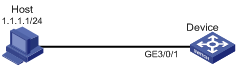
Configuration procedure
# Create advanced ACL 3000, and configure a rule to match packets whose source port number is not 21.
<DeviceA> system-view
[DeviceA] acl number 3000
[DeviceA-acl-adv-3000] rule 0 permit tcp source-port neq 21
[DeviceA-acl-adv-3000] quit
# Create a class named classifier_1, and use ACL 3000 as the match criterion in the class.
[DeviceA] traffic classifier classifier_1
[DeviceA-classifier-classifier_1] if-match acl 3000
[DeviceA-classifier-classifier_1] quit
# Create a behavior named behavior_1, and configure the traffic filtering action to drop packets.
[DeviceA] traffic behavior behavior_1
[DeviceA-behavior-behavior_1] filter deny
[DeviceA-behavior-behavior_1] quit
# Create a policy named policy, and associate class classifier_1 with behavior behavior_1 in the policy.
[DeviceA] qos policy policy
[DeviceA-qospolicy-policy] classifier classifier_1 behavior behavior_1
[DeviceA-qospolicy-policy] quit
# Apply the policy named policy to the incoming traffic of GigabitEthernet 3/0/1.
[DeviceA] interface GigabitEthernet 3/0/1
[DeviceA-GigabitEthernet3/0/1] qos apply policy policy inbound
Overview
Configuration procedure
To configure protocol packet rate limiting:
|
Step |
Command |
Remarks |
|
1. Enter system view. |
system-view |
N/A |
|
2. Create a class and enter class view. |
traffic classifier tcl-name [ operator { and | or } ] |
N/A |
|
3. Configure match criteria. |
if-match match-criteria |
N/A |
|
4. Return to system view. |
quit |
N/A |
|
5. Create a behavior and enter behavior view. |
traffic behavior behavior-name |
N/A |
|
6. Configure protocol packet rate limiting. |
packet-rate value |
The value argument is in pps. |
|
7. Return to system view. |
quit |
N/A |
|
8. Create a policy and enter policy view. |
qos policy policy-name |
N/A |
|
9. Associate the class with the traffic behavior in the QoS policy. |
classifier tcl-name behavior behavior-name |
N/A |
|
10. Return to system view. |
quit |
N/A |
|
11. Apply the QoS policy to the control plane. |
N/A |
|
|
12. Display the protocol packet rate limiting configuration. |
display traffic behavior user-defined [ behavior-name ] [ | { begin | exclude | include } regular-expression ] |
Optional. Available in any view. |
Protocol packet rate limiting configuration example
Network requirements
As shown in Figure 20, multiple hosts are connected to Device through switches.
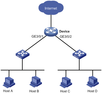
Configuration procedures
# Create class classifier_1, and configure the class to match system-index 19, which represents DHCP snooping protocol packets. You can use the display qos policy control-plane pre-defined command to see that system index 19 matches DHCP snooping protocol packets.
<Device> system-view
[Device] traffic classifier classifier_1
[Device-classifier-classifier_1] if-match system-index 19
[Device-classifier-classifier_1] quit
# Create behavior behavior_1, and configure the behavior to limit the packet rate to 500 pps.
[Device] traffic behavior behavior_1
[Device-behavior-behavior_1] packet-rate 500
[Device-behavior-behavior_1] quit
# Create a policy named policy, and associate class classifier_1 with behavior behavior_1 in the policy.
[Device] qos policy policy
[Device-qospolicy-policy] classifier classifier_1 behavior behavior_1
[Device-qospolicy-policy] quit
# Apply the QoS policy to the incoming traffic of the control plane of the card in slot 3.
[Device] control-plane slot 3
[Device-cp-slot3] qos apply policy policy inbound
[Device-cp-slot3] quit
Overview
Priority marking sets the priority fields or flag bits of packets to modify the priority of traffic. For example, you can use priority marking to set IP precedence or DSCP for a class of IP traffic to change its transmission priority in the network.
Configuration procedure
To configure priority marking:
|
Step |
Command |
Remarks |
|
1. Enter system view. |
system-view |
N/A |
|
2. Create a class and enter class view. |
traffic classifier tcl-name [ operator { and | or } ] |
N/A |
|
3. Configure match criteria. |
if-match match-criteria |
N/A |
|
4. Return to system view. |
quit |
N/A |
|
5. Create a behavior and enter behavior view. |
traffic behavior behavior-name |
N/A |
|
6. Set the DSCP value for packets. |
remark dscp dscp-value |
Optional. |
|
7. Set the 802.1p priority for packets. |
remark dot1p 8021p |
Optional. |
|
8. Set the drop precedence for packets. |
remark drop-precedence drop-precedence-value |
Optional. Applicable to only the outbound direction. |
|
9. Set the local precedence for packets. |
remark local-precedence local-precedence |
Optional. |
|
10. Return to system view. |
quit |
N/A |
|
11. Create a policy and enter policy view. |
qos policy policy-name |
N/A |
|
12. Associate the class with the traffic behavior in the QoS policy. |
classifier tcl-name behavior behavior-name |
N/A |
|
13. Return to system view. |
quit |
N/A |
|
14. Apply the QoS policy. |
· Applying the QoS policy to an interface |
Choose one application destination as needed. |
|
15. Display the priority marking configuration. |
display traffic behavior user-defined [ behavior-name ] [ | { begin | exclude | include } regular-expression ] |
Optional. Available in any view. |
Priority marking configuration example
Network requirements
As shown in Figure 21, the enterprise network of a company interconnects hosts with servers through Device. The network is described as follows:
· Host A and Host B are connected to GigabitEthernet 3/0/1 of Device.
· The data server, mail server, and file server are connected to GigabitEthernet 3/0/1 of Device.
Configure priority marking on Device to meet the following requirements:
|
Traffic source |
Destination |
Processing priority |
|
Host A, B |
Data server |
High |
|
Host A, B |
Mail server |
Medium |
|
Host A, B |
File server |
Low |
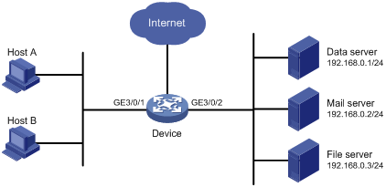
Configuration procedure
# Create advanced ACL 3000, and configure a rule to match packets with destination IP address 192.168.0.1.
<Device> system-view
[Device] acl number 3000
[Device-acl-adv-3000] rule permit ip destination 192.168.0.1 0
[Device-acl-adv-3000] quit
# Create advanced ACL 3001, and configure a rule to match packets with destination IP address 192.168.0.2.
[Device] acl number 3001
[Device-acl-adv-3001] rule permit ip destination 192.168.0.2 0
[Device-acl-adv-3001] quit
# Create advanced ACL 3002, and configure a rule to match packets with destination IP address 192.168.0.3.
[Device] acl number 3002
[Device-acl-adv-3002] rule permit ip destination 192.168.0.3 0
[Device-acl-adv-3002] quit
# Create a class named classifier_dbserver, and use ACL 3000 as the match criterion in the class.
[Device] traffic classifier classifier_dbserver
[Device-classifier-classifier_dbserver] if-match acl 3000
[Device-classifier-classifier_dbserver] quit
# Create a class named classifier_mserver, and use ACL 3001 as the match criterion in the class.
[Device] traffic classifier classifier_mserver
[Device-classifier-classifier_mserver] if-match acl 3001
[Device-classifier-classifier_mserver] quit
# Create a class named classifier_fserver, and use ACL 3002 as the match criterion in the class.
[Device] traffic classifier classifier_fserver
[Device-classifier-classifier_fserver] if-match acl 3002
[Device-classifier-classifier_fserver] quit
# Create a behavior named behavior_dbserver, and configure the action of setting the local precedence value to 4.
[Device] traffic behavior behavior_dbserver
[Device-behavior-behavior_dbserver] remark local-precedence 4
[Device-behavior-behavior_dbserver] quit
# Create a behavior named behavior_mserver, and configure the action of setting the local precedence value to 3.
[Device] traffic behavior behavior_mserver
[Device-behavior-behavior_mserver] remark local-precedence 3
[Device-behavior-behavior_mserver] quit
# Create a behavior named behavior_fserver, and configure the action of setting the local precedence value to 2.
[Device] traffic behavior behavior_fserver
[Device-behavior-behavior_fserver] remark local-precedence 2
[Device-behavior-behavior_fserver] quit
# Create a policy named policy_server, and associate classes with behaviors in the policy.
[Device] qos policy policy_server
[Device-qospolicy-policy_server] classifier classifier_dbserver behavior behavior_dbserver
[Device-qospolicy-policy_server] classifier classifier_mserver behavior behavior_mserver
[Device-qospolicy-policy_server] classifier classifier_fserver behavior behavior_fserver
[Device-qospolicy-policy_server] quit
# Apply the policy named policy_server to the incoming traffic of GigabitEthernet 3/0/1.
[Device] interface GigabitEthernet 3/0/1
[Device-GigabitEthernet3/0/1] qos apply policy policy_server inbound
[Device-GigabitEthernet3/0/1] quit
Overview
Traffic redirecting is the action of redirecting the packets matching the specific match criteria to a certain location for processing.
The following redirect actions are supported:
· Redirecting traffic to the CPU—Redirects packets that require processing by the CPU to the CPU.
· Redirecting traffic to an interface—Redirects packets that require processing by an interface to the interface. This action applies to only Layer 2 packets, and the target interface must be a Layer 2 interface.
· Redirecting traffic to the next hop—Redirects packets that require processing by an interface to the interface. This action only applies to Layer 3 packets.
Configuration restrictions and guidelines
When you configure traffic redirecting, follow these guidelines:
· The actions of redirecting traffic to the CPU, redirecting traffic to an interface, and redirecting traffic to the next hop are mutually exclusive with each other in the same traffic behavior.
· If you specify a next hop as the redirect destination, make sure the traffic identified by match criteria has the same IP version as the IP address of the next hop. For example, if the next hop is an IPv4 node, avoid using an IPv6 ACL for classification.
· The default of the fail-action keyword, if supported, is forward.
· You can use the display traffic behavior user-defined [ behavior-name ] [ | { begin | exclude | include } regular-expression ] command to view the traffic redirecting configuration.
· In IRF mode, the switch does not support redirecting traffic to an aggregate interface.
· Different from looking up the routing table based on the destination address of an IP packet, the policy-based routing (the action of redirecting traffic to the next hop) can flexibly select routes for traffic based on source IP address, and so on. The policy-based routing takes precedence over common routing. A packet is forwarded according to common routing if it does not match the policy-based routing configuration.
· On a switch operating in IRF mode, when you configure cross-switch traffic redirecting to a port of an OAA card, make sure the port of the OAA card is in VLAN 1.
· In standalone mode, the switch does not support redirecting traffic to an aggregate interface on an LST1IPS2A1 card.
· In IRF mode, the switch does not support redirecting traffic to the second internal port on an LST1IPS2A1 card on another member device.
· To redirect traffic correctly to an internal port on an LST1IPS2A1 card by using a QoS policy, you must perform the following tasks:
¡ Assign the two internal ports to an aggregation group.
¡ Set the minimum number of Selected ports in the aggregation group to 2.
Additionally, do not assign any other interface to the aggregation group.
Configuration procedure
To configure traffic redirecting:
|
Step |
Command |
Remarks |
|
1. Enter system view. |
system-view |
N/A |
|
2. Create a class and enter class view. |
traffic classifier tcl-name [ operator { and | or } ] |
N/A |
|
3. Configure match criteria. |
if-match match-criteria |
N/A |
|
4. Return to system view. |
quit |
N/A |
|
5. Create a behavior and enter behavior view. |
traffic behavior behavior-name |
N/A |
|
6. Configure a traffic redirecting action. |
redirect { cpu | interface interface-type interface-number [ vlan vlan-id ] | next-hop { ipv4-add1 [ ipv4-add2 ] | ipv6-add1 [ interface-type interface-number ] [ ipv6-add2 [ interface-type interface-number ] ] } [ fail-action { discard | forward } ] } |
Optional. |
|
7. Return to system view. |
quit |
N/A |
|
8. Create a policy and enter policy view. |
qos policy policy-name |
N/A |
|
9. Associate the class with the traffic behavior in the QoS policy. |
classifier tcl-name behavior behavior-name |
N/A |
|
10. Return to system view. |
quit |
N/A |
|
11. Apply the QoS policy. |
· Applying the QoS policy to an interface |
Choose one application destination as needed. |
Traffic redirecting configuration example
|
|
IMPORTANT: By default, Ethernet, VLAN, and aggregate interfaces are down. To configure traffic redirecting for any of them, use the undo shutdown command on the interface to bring it up first. |
Network requirements
As shown in Figure 22, the network is described as follows:
· Device A is connected to Device through two links. At the same time, Device A and Device B are each connected to other devices.
· GigabitEthernet 3/0/2 of Device A and GigabitEthernet 3/0/2 of Device B belong to VLAN 200.
· GigabitEthernet 3/0/3 of Device A and GigabitEthernet 3/0/3 of Device B belong to VLAN 201.
· On Device A, the IP address of VLAN-interface 200 is 200.1.1.1/24, and that of VLAN-interface 201 is 201.1.1.1/24.
· On Device B, the IP address of VLAN-interface 200 is 200.1.1.2/24, and that of VLAN-interface 201 is 201.1.1.2/24.
Configure the actions of redirecting traffic to the next hop to implement policy-based routing and meet the following requirements:
· Packets with source IP address 2.1.1.1 received on GigabitEthernet 3/0/1 of Device A are forwarded to IP address 200.1.1.2.
· Packets with source IP address 2.1.1.2 received on GigabitEthernet 3/0/1 of Device A are forwarded to IP address 201.1.1.2.
· Other packets received on GigabitEthernet 3/0/1 of Device A are forwarded according to the routing table.
Configuration procedure
# Create basic ACL 2000, and configure a rule to match packets with source IP address 2.1.1.1.
<DeviceA> system-view
[DeviceA] acl number 2000
[DeviceA-acl-basic-2000] rule permit source 2.1.1.1 0
[DeviceA-acl-basic-2000] quit
# Create basic ACL 2001, and configure a rule to match packets with source IP address 2.1.1.2.
[DeviceA] acl number 2001
[DeviceA-acl-basic-2001] rule permit source 2.1.1.2 0
[DeviceA-acl-basic-2001] quit
# Create a class named classifier_1, and use ACL 2000 as the match criterion in the class.
[DeviceA] traffic classifier classifier_1
[DeviceA-classifier-classifier_1] if-match acl 2000
[DeviceA-classifier-classifier_1] quit
# Create a class named classifier_2, and use ACL 2001 as the match criterion in the class.
[DeviceA] traffic classifier classifier_2
[DeviceA-classifier-classifier_2] if-match acl 2001
[DeviceA-classifier-classifier_2] quit
# Create a behavior named behavior_1, and configure the action of redirecting traffic to the next hop 200.1.1.2.
[DeviceA] traffic behavior behavior_1
[DeviceA-behavior-behavior_1] redirect next-hop 200.1.1.2
[DeviceA-behavior-behavior_1] quit
# Create a behavior named behavior_2, and configure the action of redirecting traffic to the next hop 200.1.1.2.
[DeviceA] traffic behavior behavior_2
[DeviceA-behavior-behavior_2] redirect next-hop 201.1.1.2
[DeviceA-behavior-behavior_2] quit
# Create a policy named policy, associate class classifier_1 with behavior behavior_1, and associate class classifier_2 with behavior behavior_2 in the policy.
[DeviceA] qos policy policy
[DeviceA-qospolicy-policy] classifier classifier_1 behavior behavior_1
[DeviceA-qospolicy-policy] classifier classifier_2 behavior behavior_2
[DeviceA-qospolicy-policy] quit
# Apply the policy named policy to the incoming traffic of GigabitEthernet 3/01.
[DeviceA] interface GigabitEthernet 3/0/1
[DeviceA-GigabitEthernet 3/0/1] qos apply policy policy inbound
Overview
Global committed access rate (CAR) is an approach to policing traffic flows globally. It adds flexibility to common CAR where traffic policing is performed only on a per-class or per-interface basis. In this approach, CAR actions are created in system view and each can be referenced to police multiple traffic flows as a whole. Only aggregate CAR is supported.
An aggregate CAR action is created globally and can be directly applied to interfaces or referenced in the traffic behaviors associated with different traffic classes to police multiple traffic flows as a whole. The total rate of the traffic flows must conform to the traffic policing specifications set in the aggregate CAR action.
Configuring aggregate CAR
Configuration procedure
To configure aggregate CAR:
|
Step |
Command |
Remarks |
|
1. Enter system view. |
system-view |
N/A |
|
2. Configure an aggregate CAR action. |
qos car car-name aggregative cir committed-information-rate [ cbs committed-burst-size [ ebs excess-burst-size ] ] [ pir peek-information-rate ] [ red action ] |
N/A |
|
3. Enter behavior view. |
traffic behavior behavior-name |
N/A |
|
4. Reference the aggregate CAR in the traffic behavior. |
car name car-name |
N/A |
|
5. Display the traffic behavior configuration information. |
display traffic behavior user-defined [ behavior-name ] [ | { begin | exclude | include } regular-expression ] |
Optional. Available in any view. |
|
6. Display the configuration and statistics for the specified aggregate CAR. |
display qos car name [ car-name ] [ | { begin | exclude | include } regular-expression ] |
Optional. Available in any view. |
Configuration example
# Create an aggregate CAR action named aggcar-1, and configure the following parameters for it: CIR 200, CBS 2000, and dropping red packets. Reference aggregate CAR aggcar-1 in behavior be1.
<Sysname> system-view
[Sysname] qos car aggcar-1 aggregative cir 200 cbs 2000 red discard
[Sysname] traffic behavior be1
[Sysname-behavior-be1] car name aggcar-1
Overview
Configuration procedure
|
Step |
Command |
Remarks |
|
1. Enter system view. |
system-view |
N/A |
|
2. Create a class and enter class view. |
traffic classifier tcl-name [ operator { and | or } ] |
N/A |
|
3. Configure match criteria. |
if-match match-criteria |
N/A |
|
4. Return to system view. |
quit |
N/A |
|
5. Create a behavior and enter behavior view. |
traffic behavior behavior-name |
N/A |
|
6. Configure the accounting action. |
accounting { byte | packet } |
Optional. · byte: Counts traffic in bytes. · packet: Counts traffic in packets. |
|
7. Return to system view. |
quit |
N/A |
|
8. Create a policy and enter policy view. |
qos policy policy-name |
N/A |
|
9. Associate the class with the traffic behavior in the QoS policy. |
classifier tcl-name behavior behavior-name |
N/A |
|
10. Return to system view. |
quit |
N/A |
|
11. Apply the QoS policy. |
· Applying the QoS policy to an interface |
Choose one application destination as needed. |
Displaying and maintaining class-based accounting
To verify the class-based accounting configuration, use the display qos policy command in any view to display the traffic statistics collected after the configuration is complete.
Class-based accounting configuration example
|
|
IMPORTANT: By default, Ethernet, VLAN, and aggregate interfaces are down. To configure traffic redirecting for any of them, use the undo shutdown command on the interface to bring it up first. |
Network requirements
As shown in Figure 23, Host is connected to GigabitEthernet 3/0/1 of Device.
Configuration procedure
# Create basic ACL 2000, and configure a rule to match packets with source IP address 1.1.1.1.
<DeviceA> system-view
[DeviceA] acl number 2000
[DeviceA-acl-basic-2000] rule permit source 1.1.1.1 0
[DeviceA-acl-basic-2000] quit
# Create a class named classifier_1, and use ACL 2000 as the match criterion in the class.
[DeviceA] traffic classifier classifier_1
[DeviceA-classifier-classifier_1] if-match acl 2000
[DeviceA-classifier-classifier_1] quit
# Create a behavior named behavior_1, and configure the traffic accounting action.
[DeviceA] traffic behavior behavior_1
[DeviceA-behavior-behavior_1] accounting
[DeviceA-behavior-behavior_1] quit
# Create a policy named policy, and associate class classifier_1 with behavior behavior_1 in the policy.
[DeviceA] qos policy policy
[DeviceA-qospolicy-policy] classifier classifier_1 behavior behavior_1
[DeviceA-qospolicy-policy] quit
# Apply the policy named policy to the incoming traffic of GigabitEthernet 3/0/1.
[DeviceA] interface GigabitEthernet 3/0/1
[DeviceA-GigabitEthernet3/0/1] qos apply policy policy inbound
[DeviceA-GigabitEthernet3/0/1] quit
# Display traffic statistics to verify the configuration.
[DeviceA] display qos policy interface GigabitEthernet 3/0/1
Interface: GigabitEthernet3/0/1
Direction: Inbound
Policy: policy
Classifier: classifier_1
Operator: AND
Rule(s) : If-match acl 2000
Behavior: behavior_1
Accounting Enable:
28529 (Packets)
Overview
A device provides two counters to collect outbound and inbound traffic statistics.
You can configure each counter to collect statistics for traffic on a card, or traffic identified by any combination of interface, VLAN, local precedence, and drop precedence.
You can enable the two counters at the same time. They collect statistics independently.
|
|
NOTE: The difference between class-based accounting and traffic accounting lies in that traffic accounting collects statistics according to system-defined statistics collecting rules and class-based accounting collects statistics for user-defined traffic classes. |
Configuration procedure
|
Step |
Command |
Remarks |
|
1. Enter system view. |
system-view |
N/A |
|
2. Enable traffic accounting and specify the type of traffic. |
· In standalone mode · In IRF mode: |
By default, traffic accounting is disabled. |
|
|
NOTE: The local-precedence and drop-priority keywords apply on in the outbound direction. The drop-priority keyword applies only in the outbound direction. |
Displaying and maintaining traffic accounting
|
Task |
Command |
Remarks |
|
Display traffic statistics collected by the traffic accounting function in standalone mode. |
display qos traffic-counter { inbound | outbound } { counter0 | counter1 } slot slot-number [ | { begin | exclude | include } regular-expression ] |
Available in any view. |
|
Display traffic statistics collected by the traffic accounting function in IRF mode. |
display qos traffic-counter { inbound | outbound } { counter0 | counter1 } chassis chassis-number slot slot-number [ | { begin | exclude | include } regular-expression ] |
Available in any view. |
|
Clear the traffic statistics collected by a counter of the traffic accounting function in standalone mode. |
reset qos traffic-counter { inbound | outbound } { counter0 | counter1 } slot slot-number |
Available in user view. |
|
Clear the traffic statistics collected by a counter of the traffic accounting function in IRF mode. |
reset qos traffic-counter { inbound | outbound } { counter0 | counter1 } chassis chassis-number slot slot-number |
Available in user view. |
|
Step |
Command |
Remarks |
|
1. Enter system view. |
system-view |
N/A |
|
2. Enable or disable enhanced QoS. |
enhanced-qos enable |
Optional. By default, enhanced QoS is enabled. |
Overview
Suppose a device is not configured with the QoS pipe mode and the device performs any of the following roles:
· A backbone core bridge (BCB) in a MAC-in-MAC network.
· An egress provider edge (PE) in an MPLS L2VPN network.
· An egress PE in an MPLS L3VPN network.
· An egress PE in a VPLS network.
If the device receives a packet carrying the DSCP field, the device changes the DSCP value to 0, and then forwards the packet to downstream devices. If a downstream device is configured with priority mapping, the downstream device will map the DSCP value of the IP packet to packet scheduling priority values (such as local precedence, drop precedence, and user precedence), and effectively, thoroughly control the forwarding and scheduling priority of the packet. As a result, if the DSCP value of the packet is changed, the forwarding and scheduling of the IP packet on the downstream devices are affected, or even the packet might be dropped.
With the QoS pipe mode configured, packets can pass through any of the networks mentioned above and keep their DSCP values unchanged. As a result, the forwarding and scheduling of the IP packets on the downstream devices are not affected.
For more information about MAC-in-MAC, see Layer 2—LAN Switching Configuration Guide. For more information about MPLS L2VPN, MPLS L3VPN, and VPLS, see MPLS Configuration Guide.
Configuration procedure
To configure the QoS pipe mode:
|
Step |
Command |
Remarks |
|
1. Enter system view |
system-view |
N/A |
|
2. Configure the QoS pipe mode |
qos pipe-mode |
By default, the QoS pipe mode is not configured. |
Appendix A Acronym
Table 2 Appendix A Acronym
|
Acronym |
Full spelling |
|
AF |
Assured Forwarding |
|
BE |
Best Effort |
|
CAR |
Committed Access Rate |
|
CBS |
Committed Burst Size |
|
CBQ |
Class Based Queuing |
|
CBWFQ |
Class Based Weighted Fair Queuing |
|
CE |
Customer Edge |
|
CIR |
Committed Information Rate |
|
CQ |
Custom Queuing |
|
DAR |
Deeper Application Recognition |
|
DiffServ |
Differentiated Service |
|
DSCP |
Differentiated Services Codepoint |
|
EACL |
Enhanced ACL |
|
EBS |
Excess Burst Size |
|
EF |
Expedited Forwarding |
|
FEC |
Forwarding Equivalence Class |
|
FIFO |
First in First out |
|
GTS |
Generic Traffic Shaping |
|
IntServ |
Integrated Service |
|
ISP |
Internet Service Provider |
|
LFI |
Link Fragmentation & Interleaving |
|
LLQ |
Low Latency Queuing |
|
LSP |
Label Switched Path |
|
MPLS |
Multiprotocol Label Switching |
|
PE |
Provider Edge |
|
PHB |
Per-hop Behavior |
|
PIR |
Peak Information Rate |
|
PQ |
Priority Queuing |
|
QoS |
Quality of Service |
|
QPPB |
QoS Policy Propagation Through the Border Gateway Protocol |
|
RED |
Random Early Detection |
|
RSVP |
Resource Reservation Protocol |
|
RTP |
Real-time Transport Protocol |
|
SLA |
Service Level Agreement |
|
TE |
Traffic Engineering |
|
ToS |
Type of Service |
|
TP |
Traffic Policing |
|
TS |
Traffic Shaping |
|
VoIP |
Voice over IP |
|
VPN |
Virtual Private Network |
|
WFQ |
Weighted Fair Queuing |
|
WRED |
Weighted Random Early Detection |
Appendix B Default priority mapping tables
Introduction to priority mapping tables
The switch provides various types of priority mapping table, as listed below.
Table 3 The default dot1p-lp, dot1p-dp, dot1p-dscp, and dot1p-exp mappings
|
Input priority value |
dot1p-lp mapping |
dot1p-dp mapping |
dot1p-dscp mapping |
dot1p-exp mapping |
|
0 |
2 |
0 |
0 |
0 |
|
1 |
0 |
0 |
8 |
1 |
|
2 |
1 |
0 |
16 |
2 |
|
3 |
3 |
0 |
24 |
3 |
|
4 |
4 |
0 |
32 |
4 |
|
5 |
5 |
0 |
40 |
5 |
|
6 |
6 |
0 |
48 |
6 |
|
7 |
7 |
0 |
56 |
7 |
Table 4 The default dscp-lp, dscp-dp, dscp-dot1p, and dscp-exp mappings
|
Input priority value |
dscp-lp mapping |
dscp-dp mapping |
dscp-dot1p mapping |
dscp-exp mapping |
|
0 to 7 |
0 |
0 |
0 |
0 |
|
8 to 15 |
1 |
0 |
1 |
1 |
|
16 to 23 |
2 |
0 |
2 |
2 |
|
24 to 31 |
3 |
0 |
3 |
3 |
|
32 to 39 |
4 |
0 |
4 |
4 |
|
40 to 47 |
5 |
0 |
5 |
5 |
|
48 to 55 |
6 |
0 |
6 |
6 |
|
56 to 63 |
7 |
0 |
7 |
7 |
Table 5 The default exp-dscp, exp-dp, exp-dot1p, and exp-lp mappings
|
Input priority value |
exp-dscp mapping |
exp-dp mapping |
exp-dot1p mapping |
exp-lp mapping |
|
0 |
0 |
0 |
0 |
0 |
|
1 |
8 |
0 |
1 |
1 |
|
2 |
16 |
0 |
2 |
2 |
|
3 |
24 |
0 |
3 |
3 |
|
4 |
32 |
0 |
4 |
4 |
|
5 |
40 |
0 |
5 |
5 |
|
6 |
48 |
0 |
6 |
6 |
|
7 |
56 |
0 |
7 |
7 |
Table 6 The default up-dp, up-lp, up-up, and up-rpr mappings
|
Input priority value |
up-dp mapping |
up-lp mapping |
up-up mapping |
up-rpr mapping |
|
0 |
0 |
0 |
0 |
0 |
|
1 |
0 |
1 |
1 |
0 |
|
2 |
0 |
2 |
2 |
1 |
|
3 |
0 |
3 |
3 |
1 |
|
4 |
0 |
4 |
4 |
2 |
|
5 |
0 |
5 |
5 |
2 |
|
6 |
0 |
6 |
6 |
2 |
|
7 |
0 |
7 |
7 |
2 |
Introduction to colored priority mapping tables
Packets processed by CAR are colored green, yellow, or red. To perform priority mapping for packets in different colors, the switch provides multiple colored priority mapping tables, as described in subsections.
dot1p-dot1p mapping
The output value equals the input value in all conditions.
dot1p-dp mapping
Table 7 The default dot1p-dp mapping table
|
Input value |
dot1p-dp mapping (inbound) |
||
|
green |
yellow |
red |
|
|
0 to 7 |
0 |
1 |
2 |
dot1p-dscp
The output value equals the input value multiplied by 8 in all conditions.
dot1p-exp
The output value equals the input value in all conditions.
dot1p-lp
Table 8 The default dot1p-lp mapping table
|
Input value |
dot1p-lp mapping (inbound) |
||
|
green |
yellow |
red |
|
|
0 |
2 |
2 |
2 |
|
1 |
0 |
0 |
0 |
|
2 |
1 |
1 |
1 |
|
3 |
3 |
3 |
3 |
|
4 |
4 |
4 |
4 |
|
5 |
5 |
5 |
5 |
|
6 |
6 |
6 |
6 |
|
7 |
7 |
7 |
7 |
dscp-dot1p
Table 9 The default dscp-dot1p mapping table
|
Input value |
dscp-dot1p mapping |
||
|
green |
yellow |
red |
|
|
0 to 7 |
0 |
0 |
0 |
|
8 to 15 |
1 |
1 |
1 |
|
16 to 23 |
2 |
2 |
2 |
|
24 to 31 |
3 |
3 |
3 |
|
32 to 39 |
4 |
4 |
4 |
|
40 to 47 |
5 |
5 |
5 |
|
48 to 55 |
6 |
6 |
6 |
|
56 to 63 |
7 |
7 |
7 |
dscp-dp
Table 10 The default dscp-dp mapping table
|
Input value |
dscp-dp mapping (inbound) |
||
|
green |
yellow |
red |
|
|
0 to 63 |
0 |
1 |
2 |
dscp-dscp
The output value equals the input value in all conditions.
dscp-exp
Table 11 The default dscp-exp mapping table
|
Input value |
dscp-exp mapping |
||
|
green |
yellow |
red |
|
|
0 to 7 |
0 |
0 |
0 |
|
8 to 15 |
1 |
1 |
1 |
|
16 to 23 |
2 |
2 |
2 |
|
24 to 31 |
3 |
3 |
3 |
|
32 to 39 |
4 |
4 |
4 |
|
40 to 47 |
5 |
5 |
5 |
|
48 to 55 |
6 |
6 |
6 |
|
56 to 63 |
7 |
7 |
7 |
dscp-lp
Table 12 The default dscp-lp mapping table
|
Input value |
dscp-lp mapping (inbound) |
||
|
green |
yellow |
red |
|
|
0–7 |
0 |
0 |
0 |
|
8–15 |
1 |
1 |
1 |
|
16–23 |
2 |
2 |
2 |
|
24–31 |
3 |
3 |
3 |
|
32–39 |
4 |
4 |
4 |
|
40–47 |
5 |
5 |
5 |
|
48–55 |
6 |
6 |
6 |
|
56–63 |
7 |
7 |
7 |
exp-dot1p
The output value equals the input value in all conditions.
exp-dp
Table 13 The default exp-dp mapping table
|
Input value |
exp-dp mapping (inbound) |
||
|
green |
yellow |
red |
|
|
0 to 7 |
0 |
1 |
2 |
exp-dscp
The output value equals the input value multiplied by 8 in all conditions.
exp-exp
The output value equals the input value in all conditions.
exp-lp
The output value equals the input value in all conditions.
up-dscp
Table 14 The default up-dscp mapping table for green, yellow, and red packets
|
Input priority value |
up-dscp mapping |
|
up |
dscp |
|
0 |
0 |
|
1 |
8 |
|
2 |
16 |
|
3 |
24 |
|
4 |
32 |
|
5 |
40 |
|
6 |
48 |
|
7 |
56 |
|
|
NOTE: · The mappings described in this section apply to both directions unless otherwise specified. · The priority used for colored priority mapping table lookup depends on the configuration of trusted priority on the port and the priority re-marking result. |
Appendix C Introduction to packet precedences
IP precedence and DSCP values
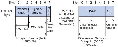
As shown in Figure 24, the ToS field in the IP header contains 8 bits. The first 3 bits (0 to 2) represent IP precedence from 0 to 7. According to RFC 2474, the ToS field is redefined as the differentiated services (DS) field, where a DSCP value is represented by the first 6 bits (0 to 5) and is in the range 0 to 63. The remaining 2 bits (6 and 7) are reserved.
Table 15 IP precedence
|
IP precedence (decimal) |
IP precedence (binary) |
Description |
|
0 |
000 |
Routine |
|
1 |
001 |
priority |
|
2 |
010 |
immediate |
|
3 |
011 |
flash |
|
4 |
100 |
flash-override |
|
5 |
101 |
critical |
|
6 |
110 |
internet |
|
7 |
111 |
network |
Table 16 DSCP values
|
DSCP value (decimal) |
DSCP value (binary) |
Description |
|
46 |
101110 |
ef |
|
10 |
001010 |
af11 |
|
12 |
001100 |
af12 |
|
14 |
001110 |
af13 |
|
18 |
010010 |
af21 |
|
20 |
010100 |
af22 |
|
22 |
010110 |
af23 |
|
26 |
011010 |
af31 |
|
28 |
011100 |
af32 |
|
30 |
011110 |
af33 |
|
34 |
100010 |
af41 |
|
36 |
100100 |
af42 |
|
38 |
100110 |
af43 |
|
8 |
001000 |
cs1 |
|
16 |
010000 |
cs2 |
|
24 |
011000 |
cs3 |
|
32 |
100000 |
cs4 |
|
40 |
101000 |
cs5 |
|
48 |
110000 |
cs6 |
|
56 |
111000 |
cs7 |
|
0 |
000000 |
be (default) |
802.1p priority
802.1p priority lies in the Layer 2 header and applies to occasions where Layer 3 header analysis is not needed and QoS must be assured at Layer 2.
Figure 25 An Ethernet frame with an 802.1Q tag header
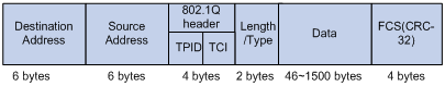
As shown in Figure 25, the 4-byte 802.1Q tag header consists of the tag protocol identifier (TPID, 2 bytes in length), whose value is 0x8100, and the tag control information (TCI, 2 bytes in length). Figure 26 shows the format of the 802.1Q tag header. The Priority field in the 802.1Q tag header is called the "802.1p priority", because its use is defined in IEEE 802.1p. Table 17 shows the values for 802.1p priority.
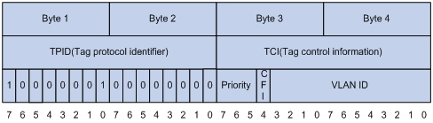
Table 17 Description on 802.1p priority
|
802.1p priority (decimal) |
802.1p priority (binary) |
Description |
|
0 |
000 |
best-effort |
|
1 |
001 |
background |
|
2 |
010 |
spare |
|
3 |
011 |
excellent-effort |
|
4 |
100 |
controlled-load |
|
5 |
101 |
video |
|
6 |
110 |
voice |
|
7 |
111 |
network-management |
EXP values
The EXP field is in MPLS labels for MPLS QoS purposes.
Figure 27 MPLS label structure
![]()
As shown in Figure 27, the EXP field is 3 bits long and is in the range of 0 to 7.