- Table of Contents
- Related Documents
-
| Title | Size | Download |
|---|---|---|
| 01-ACL Configuration | 224.49 KB |
Contents
Rule comments and rule range remarks
Configuring the ACL operating mode
Configuring an IPv4 advanced ACL
Configuring an IPv6 advanced ACL
Configuring an Ethernet frame header ACL
Configuring a user-defined ACL
Configuring a user-defined flow template
Configuration restrictions and guidelines
Configuring packet filtering with ACLs
Applying an IPv4 ACL for packet filtering
Applying an IPv6 ACL for packet filtering
Displaying and maintaining ACLs
IPv4 ACL configuration example
IPv6 ACL configuration example
IPv4 packet filtering configuration example
Flow template configuration example
For more information about the subcards mentioned in this document, see the installation guide for the product.
In this document, EB cards refer to the interface cards suffixed with EB, EC1 cards refer to the interface cards suffixed with EC1, and EF cards refer to the cards suffixed with EF.
ACL overview
An access control list (ACL) is a set of rules (or permit or deny statements) for identifying traffic based on criteria such as source IP address, destination IP address, and port number. Unless otherwise stated, ACLs refer to both IPv4 and IPv6 ACLs throughout this document.
ACLs are primarily used for packet filtering. "Configuring packet filtering with ACLs" provides an example. You can use ACLs in QoS, firewall, routing, and other feature modules for identifying traffic. The packet drop or forwarding decisions varies with the modules that use ACLs.
ACL categories
|
Category |
ACL number |
IP version |
Match criteria |
|
Basic ACLs |
2000 to 2999 |
IPv4 |
Source IPv4 address |
|
IPv6 |
Source IPv6 address |
||
|
Advanced ACLs |
3000 to 3999 |
IPv4 |
Source IPv4 address, destination IPv4 address, packet priority, protocols over IPv4, and other Layer 3 and Layer 4 header fields |
|
IPv6 |
Source IPv6 address, destination IPv6 address, packet priority, protocols over IPv6, and other Layer 3 and Layer 4 header fields |
||
|
Ethernet frame header ACLs |
4000 to 4999 |
N/A |
Layer 2 header fields, such as source and destination MAC addresses, 802.1p priority, and link layer protocol type |
|
User-defined ACLs |
5000 to 5999 |
IPv4 and IPv6 |
User specified matching patterns in protocol headers |
ACL numbering and naming
Each ACL category has a unique range of ACL numbers. When creating an ACL, you must assign it a number. In addition, you can assign the ACL a name for the ease of identification. After creating an ACL with a name, you cannot rename it or delete its name.
For an Ethernet frame header, or user-defined ACL, the ACL number and name must be globally unique. For an IPv4 basic or advanced ACLs, its ACL number and name must be unique among all IPv4 ACLs, and for an IPv6 basic or advanced ACL, among all IPv6 ACLs. You can assign an IPv4 ACL the same number and name as an IPv6 ACL.
Match order
The rules in an ACL are sorted in a specific order. When a packet matches a rule, the device stops the match process and performs the action defined in the rule. If an ACL contains overlapping or conflicting rules, the matching result and action to take depend on the rule order.
The following ACL match orders are available:
· config—Sorts ACL rules in ascending order of rule ID. A rule with a lower ID is matched before a rule with a higher ID. If you use this approach, carefully check the rule content and order.
· auto—Sorts ACL rules in depth-first order. Depth-first ordering makes sure any subset of a rule is always matched before the rule. Table 1 lists the sequence of tie breakers that depth-first ordering uses to sort rules for each type of ACL.
The match order of user-defined ACLs can only be config.
Table 1 Sort ACL rules in depth-first order
|
ACL category |
Sequence of tie breakers |
|
IPv4 basic ACL |
1. VPN instance 2. More 0s in the source IP address wildcard (more 0s means a narrower IP address range) 3. Smaller rule ID |
|
IPv4 advanced ACL |
1. VPN instance 2. Specific protocol type rather than IP (IP represents any protocol over IP) 3. More 0s in the source IP address wildcard mask 4. More 0s in the destination IP address wildcard 5. Narrower TCP/UDP service port number range 6. Smaller rule ID |
|
IPv6 basic ACL |
1. Longer prefix for the source IP address (a longer prefix means a narrower IP address range) 2. Smaller rule ID |
|
IPv6 advanced ACL |
1. Specific protocol type rather than IP (IP represents any protocol over IPv6) 2. Longer prefix for the source IPv6 address 3. Longer prefix for the destination IPv6 address 4. Narrower TCP/UDP service port number range 5. Smaller rule ID |
|
Ethernet frame header ACL |
1. More 1s in the source MAC address mask (more 1s means a smaller MAC address) 2. More 1s in the destination MAC address mask 3. Smaller rule ID |
A wildcard mask, also called an inverse mask, is a 32-bit binary and represented in dotted decimal notation. In contrast to a network mask, the 0 bits in a wildcard mask represent ‘do care’ bits, and the 1 bits represent ‘don’t care’ bits. If the 'do care' bits in an IP address are identical to the ‘do care’ bits in an IP address criterion, the IP address matches the criterion. All ‘don’t care’ bits are ignored. The 0s and 1s in a wildcard mask can be noncontiguous. For example, 0.255.0.255 is a valid wildcard mask.
Rule comments and rule range remarks
Add a comment about an ACL rule to make it easy to understand. The rule comment appears below the rule statement.
In addition, add a rule range remark to indicate the start or end of a range of rules created for the same purpose.
ACL rule numbering
What is the ACL rule numbering step
If you do not assign an ID to the rule you are creating, the system automatically assigns it a rule ID. The rule numbering step sets the increment by which the system automatically numbers rules. For example, the default ACL rule numbering step is 5. If you do not assign IDs to rules you are creating, they are numbered 0, 5, 10, 15, and so on. The wider the numbering step, the more rules you can insert between two rules.
By introducing a gap between rules rather than contiguously numbering rules, you have the flexibility of inserting rules in an ACL. This feature is important for a config order ACL, where ACL rules are matched in ascending order of rule ID.
Automatic rule numbering and renumbering
The ID automatically assigned to an ACL rule takes the nearest higher multiple of the numbering step to the current highest rule ID, starting with 0.
For example, if the numbering step is 5 (the default), and there are five ACL rules numbered 0, 5, 9, 10, and 12, the newly defined rule is numbered 15. If the ACL does not contain any rule, the first rule is numbered 0.
Whenever the step changes, the rules are renumbered, starting from 0. For example, if there are five rules numbered 5, 10, 13, 15, and 20, changing the step from 5 to 2 causes the rules to be renumbered 0, 2, 4, 6 and 8.
ACL configuration task list
|
Task |
Remarks |
|
Optional. Applicable to IPv4 and IPv6 ACLs. |
|
|
Optional. Applicable to EB cards. |
|
|
Required. Configure at least one task. Applicable to IPv4 and IPv6. |
|
|
Optional. Applicable to IPv4 and IPv6. |
|
|
Optional. Applicable to IPv4 and IPv6 ACLs. |
|
|
Optional. Applicable to IPv4 and IPv6. |
Configuring a time range
You can implement ACL rules based on the time of day by applying a time range to them. A time-based ACL rule takes effect only in any time periods specified by the time range.
The following basic types of time range are available:
· Periodic time range—Recurs periodically on a day or days of the week.
· Absolute time range—Represents only a period of time and does not recur.
You can create a maximum of 256 time ranges, each with a maximum of 32 periodic statements and 12 absolute statements. The active period of a time range is calculated as follows:
1. Combining all periodic statements
2. Combining all absolute statements
3. Taking the intersection of the two statement sets as the active period of the time range
To configure a time range:
|
Step |
Command |
Remarks |
|
1. Enter system view. |
system-view |
N/A |
|
2. Configure a time range. |
time-range time-range-name { start-time to end-time days [ from time1 date1 ] [ to time2 date2 ] | from time1 date1 [ to time2 date2 ] | to time2 date2 } |
By default, no time range exists. Repeat this command with the same time range name to create multiple statements for a time range. |
Configuring the ACL operating mode
On a switch with EB cards, you can configure the ACL operating mode to change the ACL rule length on the EB cards.
· When the EB cards are operating in standard ACL mode, the ACL rule length is 24 bytes and only Ethernet frame header, IPv4 basic, and IPv4 advanced ACLs are supported on EB cards.
· When the EB cards are operating in enhanced ACL mode, the ACL rule length is 48 bytes and Ethernet frame header, IPv4 basic, IPv4 advanced, IPv6 basic, IPv6 advanced, and user-defined ACLs are supported on EB cards.
Switching the ACL operating mode changes the ACL rule length and the number of ACL rules supported on EB cards. This might invalidate ACL-related configurations. Use this feature with caution. The number of ACL rules supported in standard ACL mode is twice the number of ACL rules supported in advanced ACL mode.
This command is available only on EB cards.
After configuring the ACL operating mode, you must restart the switch to make the configuration take effect.
To configure the ACL operating mode:
|
Step |
Command |
Remarks |
|
1. Enter system view. |
system-view |
N/A |
|
2. Configure the ACL operating mode on the EB cards. |
acl mode { standard | advanced } |
By default, EB cards operate in advanced ACL mode. |
Configuring a basic ACL
Configuring an IPv4 basic ACL
IPv4 basic ACLs match packets based only on source IP addresses.
To configure an IPv4 basic ACL:
|
Step |
Command |
Remarks |
|
1. Enter system view. |
system-view |
N/A |
|
2. Create an IPv4 basic ACL and enter its view. |
acl number acl-number [ name acl-name ] [ match-order { auto | config } ] |
By default, no ACL exists. IPv4 basic ACLs are numbered in the range 2000 to 2999. You can use the acl name acl-name command to enter the view of a named IPv4 ACL. |
|
3. Configure a description for the IPv4 basic ACL. |
description text |
Optional. By default, an IPv4 basic ACL has no ACL description. |
|
4. Set the rule numbering step. |
step step-value |
Optional. The default setting is 5. |
|
5. Create or edit a rule. |
rule [ rule-id ] { deny | permit } [ counting | fragment | logging | source { sour-addr sour-wildcard | any } | time-range time-range-name | vpn-instance vpn-instance-name ] * |
By default, an IPv4 basic ACL does not contain any rule. The logging keyword supports only the packet filter function. When the device is a PE device, the packets at the private network side of a VPN cannot match the vpn-instance vpn-instance-name option. When the device is a MCE device, packets of a VPN cannot match the vpn-instance vpn-instance-name option. For more information about PE devices and MCE devices, see MPLS Configuration Guide. |
|
6. Add or edit a rule comment. |
rule rule-id comment text |
Optional. By default, an IPv4 ACL rule has no rule description. |
|
7. Add or edit a rule range remark. |
rule [ rule-id ] remark text |
Optional. By default, no rule range remarks are configured. |
|
8. Enable rule match counting for the IPv4 basic ACL. |
hardware-count enable |
Optional. By default, rule match counting is disabled. |
Configuring an IPv6 basic ACL
|
Step |
Command |
Remarks |
|
1. Enter system view. |
system-view |
N/A |
|
2. Enable the 80-byte ACL rule match mode. |
acl ipv6 enable |
The default setting is 40 bytes on an EC1 or EF card. This command is valid only for an EC1 or EF card. To support user-defined, IPv6 basic, and IPv6 advanced ACLs on an EC1 or EF card, you must configure this command first. |
|
3. Create an IPv6 basic ACL view and enter its view. |
acl ipv6 number acl6-number [ name acl6-name ] [ match-order { auto | config } ] |
By default, no ACL exists. IPv6 basic ACLs are numbered in the range 2000 to 2999. You can use the acl ipv6 name acl6-name command to enter the view of a named IPv6 ACL. |
|
4. Configure a description for the IPv6 basic ACL. |
description text |
Optional. By default, an IPv6 basic ACL has no ACL description. |
|
5. Set the rule numbering step. |
step step-value |
Optional. The default setting is 5. |
|
6. Create or edit a rule. |
rule [ rule-id ] { deny | permit } [ counting | fragment | logging | source { ipv6-address prefix-length | ipv6-address/prefix-length | any } | time-range time-range-name | vpn-instance vpn-instance-name ] * |
By default, an IPv6 basic ACL does not contain any rule. The logging keyword supports only the packet filter function. The vpn-instance keyword is not supported in the current software version, and is reserved for future support. |
|
7. Add or edit a rule comment. |
rule rule-id comment text |
Optional. By default, an IPv6 basic ACL rule has no rule description. |
|
8. Add or edit a rule range remark. |
rule [ rule-id ] remark text |
Optional. By default, no rule range remarks are configured. |
|
9. Enable rule match counting for the IPv6 basic ACL. |
hardware-count enable |
Optional. By default, rule matching counting is disabled. |
Configuring an advanced ACL
Configuring an IPv4 advanced ACL
IPv4 advanced ACLs match packets based on source IP addresses, destination IP addresses, packet priorities, protocols over IP, and other protocol header information, such as TCP/UDP source and destination port numbers, TCP flags, ICMP message types, and ICMP message codes.
Compared to IPv4 basic ACLs, IPv4 advanced ACLs allow more flexible and accurate filtering.
To configure an IPv4 advanced ACL:
|
Step |
Command |
Remarks |
||
|
1. Enter system view. |
system-view |
N/A |
||
|
2. Create an IPv4 advanced ACL and enter its view. |
acl number acl-number [ name acl-name ] [ match-order { auto | config } ] |
By default, no ACL exists. IPv4 advanced ACLs are numbered in the range 3000 to 3999. You can use the acl name acl-name command to enter the view of a named IPv4 ACL. |
||
|
3. Configure a description for the IPv4 advanced ACL. |
description text |
Optional. By default, an IPv4 advanced ACL has no ACL description. |
||
|
4. Set the rule numbering step. |
step step-value |
Optional. The default setting is 5. |
||
|
5. Create or edit a rule. |
rule [ rule-id ] { deny | permit } protocol [ { { ack ack-value | fin fin-value | psh psh-value | rst rst-value | syn syn-value | urg urg-value } * | established } | counting | destination { dest-addr dest-wildcard | any } | destination-port operator port1 [ port2 ] | dscp dscp | fragment | icmp-type { icmp-type [ icmp-code ] | icmp-message } | logging | precedence precedence | reflective | source { sour-addr sour-wildcard | any } | source-port operator port1 [ port2 ] | time-range time-range-name | tos tos | vpn-instance vpn-instance-name ] * |
By default, an IPv4 advanced ACL does not contain any rule. The logging keyword supports only the packet filter function. The reflective keyword is not supported in the current software version, and is reserved for future support. When EB cards are operating in standard ACL mode, the cards do not support the vpn-instance keyword for IPv4 advanced ACLs. When the device is a PE device, the packets at the private network side of a VPN cannot match the vpn-instance vpn-instance-name option. When the device is a MCE device, packets of a VPN cannot match the vpn-instance vpn-instance-name option. For more information about PE devices and MCE devices, see MPLS Configuration Guide. |
||
|
6. Add or edit a rule comment. |
rule rule-id comment text |
Optional. By default, an IPv4 advanced ACL rule has no rule description. |
||
|
7. Add or edit a rule range remark. |
rule [ rule-id ] remark text |
Optional. By default, no rule range remarks are configured. |
||
|
8. Enable rule match counting for the IPv4 advanced ACL. |
hardware-count enable |
Optional. By default, rule matching counting is disabled. |
||
Configuring an IPv6 advanced ACL
IPv6 advanced ACLs match packets based on the source IPv6 addresses, destination IPv6 addresses, packet priorities, protocols carried over IPv6, and other protocol header fields such as the TCP/UDP source port number, TCP/UDP destination port number, ICMPv6 message type, and ICMPv6 message code.
Compared to IPv6 basic ACLs, IPv6 advanced ACLs allow more flexible and accurate filtering.
To configure an IPv6 advanced ACL:
|
Step |
Command |
Remarks |
|
1. Enter system view. |
system-view |
N/A |
|
2. Enable the 80-byte ACL rule match mode. |
acl ipv6 enable |
The default setting is 40 bytes on an EC1 or EF card. This command is valid only for an EC1 or EF card. To support user-defined, IPv6 basic, and IPv6 advanced ACLs on an EC1 or EF card, you must configure this command first. |
|
3. Create an IPv6 advanced ACL and enter its view. |
acl ipv6 number acl6-number [ name acl6-name ] [ match-order { auto | config } ] |
By default, no ACL exists. IPv6 advanced ACLs are numbered in the range 3000 to 3999. You can use the acl ipv6 name acl6-name command to enter the view of a named IPv6 ACL. |
|
4. Configure a description for the IPv6 advanced ACL. |
description text |
Optional. By default, an IPv6 advanced ACL has no ACL description. |
|
5. Set the rule numbering step. |
step step-value |
Optional. The default setting is 5. |
|
6. Create or edit a rule. |
rule [ rule-id ] { deny | permit } protocol [ { { ack ack-value | fin fin-value | psh psh-value | rst rst-value | syn syn-value | urg urg-value } * | established } | counting | destination { dest dest-prefix | dest/dest-prefix | any } | destination-port operator port1 [ port2 ] | dscp dscp | flow-label flow-label-value | fragment | icmp6-type { icmp6-type icmp6-code | icmp6-message } | logging | source { source source-prefix | source/source-prefix | any } | source-port operator port1 [ port2 ] | time-range time-range-name | vpn-instance vpn-instance-name ] * |
By default IPv6 advanced ACL does not contain any rule. The logging keyword supports only the packet filter function. The vpn-instance keyword is not supported in the current software version, and is reserved for future support. |
|
7. Add or edit a rule comment. |
rule rule-id comment text |
Optional. By default, an IPv6 advanced ACL rule has no rule description. |
|
8. Add or edit a rule range remark. |
rule [ rule-id ] remark text |
Optional. By default, no rule range remarks are configured. |
|
9. Enable rule match counting for the IPv6 advanced ACL. |
hardware-count enable |
Optional. By default, rule matching counting is disabled. |
Configuring an Ethernet frame header ACL
Ethernet frame header ACLs, also called "Layer 2 ACLs," match packets based on Layer 2 protocol header fields such as source MAC address, destination MAC address, 802.1p priority (VLAN priority), and link layer protocol type.
To configure an Ethernet frame header ACL:
|
Step |
Command |
Remarks |
|
1. Enter system view. |
system-view |
N/A |
|
2. Create an Ethernet frame header ACL and enter its view. |
acl number acl-number [ name acl-name ] [ match-order { auto | config } ] |
By default, no ACL exists. Ethernet frame header ACLs are numbered in the range 4000 to 4999. You can use the acl name acl-name command to enter the view of a named Ethernet frame header ACL. |
|
3. Configure a description for the Ethernet frame header ACL. |
description text |
Optional. By default, an Ethernet frame header ACL has no ACL description. |
|
4. Set the rule numbering step. |
step step-value |
Optional. The default setting is 5. |
|
5. Create or edit a rule. |
rule [ rule-id ] { deny | permit } [ cos vlan-pri | counting | dest-mac dest-addr dest-mask | { lsap lsap-type lsap-type-mask | type protocol-type protocol-type-mask } | source-mac sour-addr source-mask | time-range time-range-name ] * |
By default, an Ethernet frame header ACL does not contain any rule. The lsap keyword is not supported in the current software version, and is reserved for future support. When the EB cards are operating in standard ACL mode, the cards do not support the value 0x86DD 0xFFFF, which matches IPv6 packets, for the protocol-type protocol-type-mask argument. |
|
6. Add or edit a rule comment. |
rule rule-id comment text |
Optional. By default, an Ethernet frame header ACL rule has no rule description. |
|
7. Add or edit a rule range remark. |
rule [ rule-id ] remark text |
Optional. By default, no rule range remarks are configured. |
|
8. Enable rule match counting for the Ethernet frame header ACL. |
hardware-count enable |
Optional. By default, rule matching counting is disabled. |
Configuring a user-defined ACL
User-defined ACLs allow you to customize rules based on information in protocol headers. You can define a user-defined ACL to match packets in which a specific number of bytes after the specified offset (relative to the specified header), matches the specified match pattern after being ANDed with a match pattern mask.
To configure a user-defined ACL:
|
Step |
Command |
Remarks |
|
1. Enter system view. |
system-view |
N/A |
|
2. Enable the 80-byte ACL rule match mode. |
acl ipv6 enable |
The default setting is 40 bytes on an EC1 or EF card. This command is valid only for an EC1 or EF card. To support user-defined, IPv6 basic, and IPv6 advanced ACLs on an EC1 or EF card, you must configure this command first. |
|
3. Create a user-defined ACL and enter its view. |
acl number acl-number [ name acl-name ] |
By default, no ACL exists. The rule order of a user-defined ACL is config. User-defined ACLs are numbered in the range 5000 to 5999. You can use the acl name acl-name command to enter the view of a user-defined ACL. |
|
4. Configure a description for the user-defined ACL. |
description text |
Optional. By default, a user-defined ACL has no ACL description. |
|
5. Create or edit a rule. |
rule [ rule-id ] { deny | permit } [ { { ipv4 | ipv6 | l2 | l4 } rule-string rule-mask offset }&<1-8> ] [ time-range time-range-name ] [ counting ] |
By default, a user-defined ACL does not contain any rule. |
|
6. Add or edit a rule comment. |
rule rule-id comment text |
Optional. By default, a user-defined ACL rule has no rule description. |
|
7. Add or edit a rule range remark. |
rule [ rule-id ] remark text |
Optional. By default, no rule range remarks are configured. |
|
8. Enable rule match counting for the user-defined ACL. |
hardware-count enable |
Optional. By default, rule matching counting is disabled. |
Make sure all member switches of an IRF fabric are using the same ACL rule match mode. Therefore, you must configure the acl ipv6 enable command on both switches, or the acl ipv6 disable command on both switches. For information about IRF, see IRF Configuration Guide.
Copying an ACL
You can create an ACL by copying an existing ACL (source ACL). The new ACL (destination ACL) has the same properties and content as the source ACL, but not the same ACL number and name.
To successfully copy an ACL, make sure:
· The destination ACL number is from the same category as the source ACL number.
· The source ACL already exists but the destination ACL does not.
Copying an IPv4 ACL
|
Step |
Command |
|
1. Enter system view. |
system-view |
|
2. Copy an existing IPv4 ACL to create a new IPv4 ACL. |
acl copy { source-acl-number | name source-acl-name } to { dest-acl-number | name dest-acl-name } |
Copying an IPv6 ACL
|
Step |
Command |
|
1. Enter system view. |
system-view |
|
2. Copy an existing IPv6 ACL to generate a new one of the same category. |
acl ipv6 copy { source-acl6-number | name source-acl6-name } to { dest-acl6-number | name dest-acl6-name } |
Configuring a user-defined flow template
|
|
IMPORTANT: Flow templates are supported only on POS subcards. Ethernet interface cards do not support flow templates. |
Flow templates are sets of criteria based on header fields such as source IP address, destination IP address, source TCP port, and destination TCP port. Flow templates apply only to hardware-based ACLs. You use a flow template to limit the match criteria that can be applied to an interface. ACL rules that contain any criterion beyond the flow template on an interface cannot be assigned to hardware.
There are default flow templates and basic user-defined templates. By default, an interface uses the default flow template.
Configuration restrictions and guidelines
When you configure a user-defined flow template, follow these guidelines:
· The user-defined flow template you are applying to an interface must already exist.
· You can apply only one user-defined flow template on an interface.
· The default flow template contains these criteria: sip, dip, ip-protocol, sport, dport, icmp-code, icmp-type, tos, dscp, ip-precedence, mpls-exp, tcp-flag, and fragment.
· User-defined flow template you apply to a POS interfaces does not support smac, dmac, ethernet-protocol, or customer-vlan-id.
Configuration procedure
To create a flow template and apply it to an interface:
|
Step |
Command |
Remarks |
|
1. Enter system view. |
system-view |
N/A |
|
2. Create a basic user-defined flow template. |
flow-template flow-template-name basic { customer-vlan-id | dip | dmac | dport | dscp | ethernet-protocol | fragments | icmp-code | icmp-type | ip-precedence | ip-protocol | mpls-exp | service-cos | sip | smac | sport | tcp-flag | tos } * |
By default, no user-defined flow template exists. |
|
3. Enter interface view or port group view. |
· Enter interface view: · Enter port group view: |
Use either command. To apply the flow template to one interface, enter interface view. To apply the flow template to a group of interfaces, enter port group view. |
|
4. Apply the flow template to the interface or port group. |
flow-template flow-template-name |
The default flow template applies by default. |
Configuring packet filtering with ACLs
You can use an ACL to filter incoming or outgoing IPv4 or IPv6 packets.
With a basic or advanced ACL, you can log filtering events by specifying the logging keyword in the ACL rules and enabling the counting function. To enable counting for rule matches performed in hardware, configure the hardware-count enable command for the ACL or specify the counting keyword in the ACL rules.
You can set the packet filter to periodically send packet filtering logs to the information center as informational messages. The interval for generating and outputting packet filtering logs is configurable. The log information includes the number of matching packets and the ACL rules used in an interval. For more information about the information center, see Network Management and Monitoring Configuration Guide.
|
|
NOTE: ACLs on VLAN interfaces filter only packets forwarded at Layer 3. |
Applying an IPv4 ACL for packet filtering
Configuration restrictions and guidelines
When you use the packet-filter forwarding-layer route outbound command or its undo form to specify the outbound packet filter on a VLAN interface to filter only Layer 3 unicast packets or all packets, follow these guidelines:
· The packet-filter forwarding-layer route outbound command is available only for Ethernet interface cards.
· The packet-filter forwarding-layer route outbound or its undo form must be configured before the packet-filter { acl-number | name acl-name } outbound command. If you have configured the packet-filter { acl-number | name acl-name } outbound command on a VLAN interface, you must remove the packet filter setting, configure the packet-filter forwarding-layer route outbound or its undo form, and then re-configure the packet-filter { acl-number | name acl-name } outbound command on the VLAN interface.
· The packet-filter forwarding-layer route outbound command can cause the switch to discard BFD packets. To avoid this problem, configure an advanced ACL rule by using the rule [ rule-id ] permit udp destination-port range 3784 3785 command to permit BFD packets.
· In IRF mode, the packet-filter forwarding-layer route outbound command can cause the switch to discard sFlow packets. To avoid this problem, configure an advanced ACL rule by using the rule [ rule-id ] permit udp destination-port range eq udp-port command to permit sFlow packets. The udp-port is the port number of the sFlow collector and defaults to 6343. For information about sFlow, see Network Management and Monitoring Configuration Guide.
Configuration procedure
To apply an IPv4 ACL for packet filtering:
|
Step |
Command |
Remarks |
|
1. Enter system view. |
system-view |
N/A |
|
2. Set the outbound packet filters on VLAN interfaces to filter only Layer 3 (routed) unicast packets. |
packet-filter forwarding-layer route outbound |
Optional. By default, an outbound IPv4 packet filter filters all packets, including Layer 2 (switched) packets, on a VLAN interface. When EB cards are operating in standard ACL mode, the cards do not support this function. |
|
3. Enter interface view. |
interface interface-type interface-number |
N/A |
|
4. Apply an IPv4 basic, IPv4 advanced, Ethernet frame header, or user-defined ACL to the interface to filter packets. |
packet-filter { acl-number | name acl-name } { inbound | outbound } |
By default, no ACL is applied to any interface. On a VLAN interface: · The inbound packet filter handles only Layer 3 unicast packets. · If the packet-filter forwarding-layer route outbound command is configured, the outbound packet filter handles only Layer 3 unicast packets; if not, the outbound packet filter handles all packets. When EB cards are operating in standard ACL mode, the interfaces on these cards do not support applying a user-defined ACL to filter packets. On an Ethernet interface, the packet filter handles all packets. Avoid the case that multiple users configure the packet-filter command at the same time. Otherwise, the configuration might fail. |
|
5. Exit to system view. |
quit |
N/A |
|
6. Set the interval for generating and outputting IPv4 packet filtering logs. |
acl logging frequence frequence |
By default, the interval is 0. No IPv4 packet filtering logs are generated. |
The rule you add to an ACL that has been used by a packet filter cannot take effect if hardware resources are insufficient or the packet filter does not support the rule. Such rules are marked as uncompleted in the output from the display acl { acl-number | all | name acl-name } slot slot-number command. To successfully apply the rule, you must delete the rule and reconfigure it when hardware resources are sufficient.
Follow these guidelines when you configure a packet filter on a VLAN interface:
· Use the undo packet-filter command to remove the packet filter from the VLAN interface if the ACL application fails on an interface card, for example, because of hardware resource insufficiency. The switch applies the packet filter configured on a VLAN interface to the main processing unit and all interface cards. When an application failure occurs on an interface card, the switch cannot automatically remove the ACL that has been applied to the main processing unit or any other interface card.
· You must also use the undo packet-filter to remove the packet filter if the switch fails to update the packet filter on an interface card after you edit the ACL rules. If you do not remove the packet filter, the old ACL rules continue to take effect and the display packet-filter command shows the initial ACL application status.
Applying an IPv6 ACL for packet filtering
|
Step |
Command |
Remarks |
|
1. Enter system view. |
system-view |
N/A |
|
2. Enter interface view. |
interface interface-type interface-number |
N/A |
|
3. Apply an IPv6 basic or IPv6 advanced ACL to the interface to filter IPv6 packets. |
packet-filter ipv6 { acl6-number | name acl6-name } { inbound | outbound } |
By default, no IPv6 ACL is applied to the interface. On a VLAN interface, an inbound packet filter handles only Layer 3 unicast packets and an outbound packet filter handles all packets. On an Ethernet interface, the packet filter handles all packets. Avoid the case that multiple users configure the packet-filter ipv6 command at the same time. Otherwise, the configuration might fail. When EB cards are operating in standard ACL mode, the interfaces on these cards do not support applying IPv6 ACLs to filter packets. |
|
4. Exit to system view. |
quit |
N/A |
|
5. Set the interval for generating and outputting IPv6 packet filtering logs. |
acl ipv6 logging frequence frequence |
The default interval is 0. No IPv6 packet filtering logs are generated. |
The rule you add to an ACL that has been used by a packet filter cannot take effect if hardware resources are insufficient or the packet filter does not support the rule. Such rules are marked as uncompleted in the output from the display acl ipv6 { acl-number | all | name acl-name } slot slot-number command. To successfully apply the rule, you must delete the rule and reconfigure it when hardware resources are sufficient.
Follow these guidelines when you configure a packet filter on a VLAN interface:
· Use the undo packet-filter ipv6 command to remove the packet filter from the VLAN interface if the ACL application fails on an interface card, for example, because of hardware resource insufficiency. The switch applies the packet filter configured on a VLAN interface to the main processing unit and all interface cards. When an application failure occurs on an interface card, the switch cannot automatically remove the ACL that has been applied to the main processing unit or any other interface card.
· You must also use the undo packet-filter ipv6 to remove the packet filter if the switch fails to update the packet filter on an interface card after you edit the ACL rules. If you do not remove the packet filter, the old ACL rules continue to take effect and the display packet-filter ipv6 command shows the initial ACL application status.
Displaying and maintaining ACLs
|
Task |
Command |
Remarks |
|
Display the IPv4 ACL configuration and match statistics (standalone mode). |
display acl { acl-number | all | name acl-name } [ slot slot-number ] [ | { begin | exclude | include } regular-expression ] |
Available in any view. |
|
Display the IPv4 ACL configuration and match statistics (IRF mode). |
display acl { acl-number | all | name acl-name } [ chassis chassis-number slot slot-number ] [ | { begin | exclude | include } regular-expression ] |
Available in any view. |
|
Display the IPv6 ACL configuration and match statistics (standalone mode). |
display acl ipv6 { acl6-number | all | name acl6-name } [ slot slot-number ] [ | { begin | exclude | include } regular-expression ] |
Available in any view. |
|
Display the IPv6 ACL configuration and match statistics (IRF mode). |
display acl ipv6 { acl6-number | all | name acl6-name } [ chassis chassis-number slot slot-number ] [ | { begin | exclude | include } regular-expression ] |
Available in any view. |
|
Display the ACL operating mode of an EB card in the specified slot. |
display acl mode [ | { begin | exclude | include } regular-expression ] |
Available in any view. |
|
Display the usage of ACL resources (standalone mode). |
display acl resource [ slot slot-number ] [ | { begin | exclude | include } regular-expression ] |
Available in any view. |
|
Display the usage of ACL resources (IRF mode). |
display acl resource [ chassis chassis-number slot slot-number ] [ | { begin | exclude | include } regular-expression ] |
Available in any view. |
|
Display information about flow templates applied to interfaces. |
display flow-template user-defined [ flow-template-name ] [ | { begin | exclude | include } regular-expression ] |
Available in any view. |
|
Display the configuration of one or all user-defined flow templates. |
display flow-template interface [ interface-type interface-number ] [ | { begin | exclude | include } regular-expression ] |
Available in any view. |
|
Display application information of ACLs for packet filtering (standalone mode). |
display packet-filter { { all | interface interface-type interface-number } [ inbound | outbound ] | interface vlan-interface vlan-interface-number [ inbound | outbound ] [ slot slot-number ] } [ | { begin | exclude | include } regular-expression ] |
Available in any view. |
|
Display application information of ACLs for packet filtering (IRF mode). |
display packet-filter { { all | interface interface-type interface-number } [ inbound | outbound ] | interface vlan-interface vlan-interface-number [ inbound | outbound ] [ chassis chassis-number slot slot-number ] } [ | { begin | exclude | include } regular-expression ] |
Available in any view. |
|
Display the configuration and status of one or all time ranges. |
display time-range { time-range-name | all } [ | { begin | exclude | include } regular-expression ] |
Available in any view. |
|
Clear statistics on one or all IPv4 ACLs. |
reset acl counter { acl-number | all | name acl-name } |
Available in user view. |
|
Clear statistics on one or all IPv6 basic and advanced ACLs. |
reset acl ipv6 counter { acl6-number | all | name acl6-name } |
Available in user view. |
ACL configuration examples
|
|
IMPORTANT: By default, Ethernet, VLAN, and aggregate interfaces are down. To configure these interfaces, use the undo shutdown command to bring them up first. |
IPv4 ACL configuration example
Network requirements
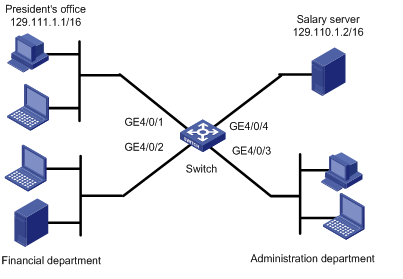
A company interconnects its departments through a switch A. Configure an ACL to:
· Permit access from the President's office at any time to the salary server.
· Deny access from any other department to the salary server during office hours (from 8:00 to 18:00) on working days.
Figure 1 Network diagram
Configuration procedure
1. Create a periodic time range from 8:00 to 18:00 on working days.
<Switch> system-view
[Switch] time-range trname 8:00 to 18:00 working-day
# Create ACL 3000, and configure an ACL rule for it.
[Switch] acl number 3000
[Switch-acl-adv-3000] rule 1 permit ip source 129.111.1.2 0.0.0.0 destination 129.110.1.2 0.0.0.0
[Switch-acl-adv-3000] quit
# Create ACL 3001, and configure an ACL rule for it.
[Switch] acl number 3001
[Switch-acl-adv-3001] rule 1 permit ip source any destination 129.110.1.2 0.0.0.0 time-range trname
[Switch-acl-adv-3001] quit
3. Define a QoS policy and apply the policy to ports:
# Create traffic classes and define traffic behaviors.
[Switch] traffic classifier test_permit
[Switch-classifier-test_permit] if-match acl 3000
[Switch-classifier-test_permit] quit
[Switch] traffic behavior test_permit
[Switch-behavior-test_permit] filter permit
[Switch-behavior-test_permit] quit
[Switch] traffic classifier test_deny
[Switch-classifier-test_deny] if-match acl 3001
[Switch-classifier-test_deny] quit
[Switch] traffic behavior test_deny
[Switch-behavior-test_deny] filter deny
[Switch-behavior-test_deny] quit
# Create a QoS policy.
[Switch] qos policy test
[Switch-qospolicy-test] classifier test_permit behavior test_permit
[Switch-qospolicy-test] classifier test_deny behavior test_deny
[Switch-qospolicy-test] quit
# Apply the QoS policy to ports GigabitEthernet 4/0/1 through GigabitEthernet 4/0/3 in the inbound direction.
[Switch] interface gigabitethernet 4/0/1
[Switch-GigabitEthernet4/0/1] qos apply policy test inbound
[Switch-GigabitEthernet4/0/1] quit
[Switch] interface gigabitethernet 4/0/2
[Switch-GigabitEthernet4/0/2] qos apply policy test inbound
[Switch-GigabitEthernet4/0/2] quit
[Switch] interface gigabitethernet 4/0/3
[Switch-GigabitEthernet4/0/3] qos apply policy test inbound
[Switch-GigabitEthernet4/0/3] quit
IPv6 ACL configuration example
Network requirements
Perform packet filtering in the inbound direction of interface GigabitEthernet 4/0/1 to deny all IPv6 packets but those with source addresses in the range 4050::9000 to 4050::90FF.
Configuration procedure
# Create ACL 2000, and define an ACL rule for it.
<Switch> system-view
[Switch] acl ipv6 number 2000
[Switch-acl6-basic-2000] rule permit source 4050::9000/120
[Switch-acl6-basic-2000] quit
# Create ACL 2001, and define an ACL rule for it.
[Switch] acl ipv6 number 2001
[Switch-acl6-basic-2001] rule permit source any
[Switch-acl6-basic-2001] quit
# Define a class and a traffic behavior to permit packets with source addresses in the range 4050::9000 to 4050::90FF.
[Switch] traffic classifier c_permit
[Switch-classifier-c_permit] if-match acl ipv6 2000
[Switch-classifier-c_permit] quit
[Switch] traffic behavior b_permit
[Switch-behavior-b_permit] filter permit
[Switch-behavior-b_permit] quit
# Define a class and a traffic behavior to deny other packets.
[Switch] traffic classifier c_deny
[Switch-classifier-c_deny] if-match acl ipv6 2001
[Switch-classifier-c_deny] quit
[Switch] traffic behavior b_deny
[Switch-behavior-b_deny] filter deny
[Switch-behavior-b_deny] quit
# Configure a QoS policy.
[Switch] qos policy test
[Switch-qospolicy-test] classifier c_permit behavior b_permit
[Switch-qospolicy-test] classifier c_deny behavior b_deny
[Switch-qospolicy-test] quit
# Apply the QoS policy to port GigabitEthernet 4/0/1 in the inbound direction.
[Switch] interface gigabitethernet 4/0/1
[Switch-GigabitEthernet4/0/1] qos apply policy test inbound
[Switch-GigabitEthernet4/0/1] quit
IPv4 packet filtering configuration example
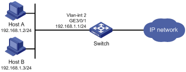
Network requirements
As shown in Figure 2, Host A and Host B connect to the switch to access the Internet.
Configure packet filtering on the VLAN interface of the switch so that everyday from 8:00 to 18:00, the VLAN-interface denies only IPv4 packets sourced from Host A. Configure the switch to output IPv4 packet filtering logs to the console at 10-minute intervals.
As actual requirements change, edit the ACL so that the VLAN interface denies only IPv4 packets sourced from Host B.
Configuration procedure
# Create a time range named study; set it to be active from 08:00 to 18:00 everyday.
<Switch> system-view
[Switch] time-range study 8:00 to 18:00 daily
# Configure VLAN 2, and assign interface GigabitEthernet 3/0/1 to this VLAN.
[Switch] vlan 2
[Switch-vlan2] port GigabitEthernet 3/0/1
[Switch-vlan2] quit
# Configure a basic IPv4 ACL 2009.
[Switch] acl number 2009
# Create an ACL rule to deny IPv4 packets sourced from 192.168.1.2/32, and configure the rule to log packet filtering events and count rule matches.
[Switch-acl-basic-2009] rule 5 deny source 192.168.1.2 0 time-range study logging counting
[Switch-acl-basic-2009] quit
# Enable the switch to generate and output IPv4 packet filtering logs at 10-minute intervals.
[Switch] acl logging frequence 10
# Apply ACL 2009 to filter incoming packets on VLAN-interface 2.
[Switch] interface vlan-interface 2
[Switch-Vlan-interface2] ip address 192.168.1.1 24
[Switch-Vlan-interface2] packet-filter 2009 inbound
[Switch-Vlan-interface2] quit
# Configure the switch to output informational log messages to the console.
[Switch] info-center source default channel 0 log level informational
# Edit ACL rule 5 in ACL 2009 to deny IPv4 packets sourced from 192.168.1.3/32. The rule takes effect on VLAN-interface 2 immediately after the modification. (The switch supports dynamic modification of ACLs in use.)
[Switch] acl number 2009
[Switch-acl-basic-2009] rule 5 deny source 192.168.1.3 0
[DeviceA-acl-basic-2009] quit
Flow template configuration example
Network requirements
Create flow templates and apply them to interfaces.
Configuration procedure
# Create basic user-defined flow template aaa.
<Sysname> system-view
[Sysname] flow-template aaa basic sip dip
# Apply user-defined flow template aaa to interface POS 3/1/1.
[Sysname] interface Pos 3/1/1
[Sysname-Pos3/1/1] flow-template aaa
# Display information about user-defined flow template aaa.
[Sysname-Pos3/1/1] display flow-template user-defined aaa
user-defined flow template: basic
name:aaa, index:1, total reference counts:1
fields: sip dip
# Display information about all user-defined flow templates.
[Sysname]display flow-template user-defined
user-defined flow template: basic
name:aaa, index:1, total reference counts:1
fields: sip dip
user-defined flow template: basic
name:1, index:2, total reference counts:0
fields: dport
user-defined flow template: basic
name:2, index:3, total reference counts:0
fields: dscp
# Delete user-defined flow template aaa. Remove it from the interface first, because it has been applied to interface POS 3/1/1.
[Sysname] interface Pos 3/1/1
[Sysname-Pos3/1/1] undo flow-template
[Sysname-Pos3/1/1] quit
[Sysname] undo flow-template name aaa