- Table of Contents
- Related Documents
-
| Title | Size | Download |
|---|---|---|
| 04-S12500_VRRP_Configuration_Examples | 328.44 KB |
Contents
Example: Configuring a single IPv4 VRRP group
Configuration restrictions and guidelines
Configuring the Layer 2 switch
Example: Configuring multiple IPv4 VRRP groups
Configuration restrictions and guidelines
Configuring the Layer 2 Switch
Example: Configuring IPv4 VRRP load balancing mode
Configuration restrictions and guidelines
Example: Configuring a single IPv6 VRRP group
Configuration restrictions and guidelines
Configuring the Layer 2 Switch
Example: Configuring multiple IPv6 VRRP groups
Configuration restrictions and guidelines
Configuring the Layer 2 Switch
Example: Configuring IPv6 VRRP load balancing mode
Configuration restrictions and guidelines
Introduction
This document provides VRRP configuration examples.
VRRP adds a group of network gateways to a VRRP group called a "virtual router." A VRRP group includes one master and multiple backups, but it has only one virtual IP address. The hosts on the subnet only need to configure this virtual IP address as their default network gateway. VRRP avoids single points of failure and simplifies the configuration on hosts.
VRRP operates in either of the following modes:
· Standard mode—Implemented based on RFCs.
· Load balancing mode—Extends the VRRP standard mode to distribute load across VRRP group members.
Prerequisites
The configuration examples in this document were created and verified in a lab environment, and all the devices started with the factory default configuration. When you are working in a live network, make sure you understand the potential impact of every command on your network.
This document assumes that you have basic knowledge of VRRP.
Example: Configuring a single IPv4 VRRP group
Network requirements
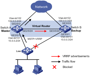
As shown in Figure 1, configure a VRRP group on Switch A and Switch B as the gateway for the hosts, and implement the following requirements:
· Switch A operates as the master to forward packets from the hosts to the external network. When Switch A fails, Switch B takes over to forward packets for the hosts.
· When the uplink interface of Switch A fails, hosts can access the external network through Switch B.
· To avoid loops between Switch A, Switch B, and the Layer 2 switch, enable MSTP on them, and specify the master as the root bridge.
Requirements analysis
To make sure Switch B can quickly become the master when Switch A fails, configure a track entry on Switch B to monitor Switch A.
To make sure hosts can access the external network when the uplink interface of Switch A fails, configure VRRP tracking on Switch A. When the uplink interface of Switch A is down or removed, Switch A decreases its priority and Switch B takes over to forward packets from Host A.
Software version used
This configuration example was created and verified on S12500-CMW520-R1825P01.
Configuration restrictions and guidelines
When you configure a single IPv4 VRRP group, follow these restrictions and guidelines:
· Configure the same virtual IP addresses for each switch in one VRRP group, and make sure the number of virtual IP addresses assigned to them is also the same.
· To avoid affecting network performance, do not create VRRP groups in the VLAN interface on a super VLAN.
· The virtual IP address assigned to the VRRP group must be a legal host address and in the same subnet as the interface IP address. The virtual IP address of a VRRP group cannot be 0.0.0.0, 255.255.255.255, loopback addresses, non-class A/B/C addresses or other illegal IP addresses such as 0.0.0.1.
Configuration procedures
Configuring Switch A
# Configure VLAN 101 and VLAN 102.
<SwitchA> system-view
[SwitchA] vlan 101
[SwitchA-vlan101] port Gigabitethernet 2/0/1
[SwitchA-vlan101] port Gigabitethernet 2/0/24
[SwitchA-vlan101] quit
[SwitchA] vlan 102
[SwitchA-vlan102] port Gigabitethernet 2/0/2
[SwitchA-vlan102] quit
[SwitchA] interface GigabitEthernet 2/0/1
[SwitchA-GigabitEthernet2/0/1] undo shutdown
[SwitchA-GigabitEthernet2/0/1] quit
[SwitchA] interface GigabitEthernet 2/0/24
[SwitchA-GigabitEthernet2/0/24] undo shutdown
[SwitchA-GigabitEthernet2/0/24] quit
[SwitchA] interface GigabitEthernet 2/0/2
[SwitchA-GigabitEthernet2/0/2] undo shutdown
[SwitchA-GigabitEthernet2/0/2] quit
# Configure the uplink interface.
[SwitchA] interface vlan-interface 102
[SwitchA-Vlan-interface102] ip address 100.0.0.2 24
[SwitchA–Vlan-interface102] undo shutdown
[SwitchA-Vlan-interface102] quit
# Create VRRP group 1.
[SwitchA] interface vlan-interface 101
[SwitchA-Vlan-interface101] ip address 10.0.0.2 24
[SwitchA-Vlan-interface101] vrrp vrid 1 virtual-ip 10.0.0.1
# Set the priority of Switch A in VRRP group 1 to 120.
[SwitchA-Vlan-interface101] vrrp vrid 1 priority 120
# Configure uplink interface tracking.
[SwitchA-Vlan-interface101] vrrp vrid 1 track interface Vlan-interface102 reduced 255
[SwitchA-Vlan-interface101] quit
# Configure MSTP.
[SwitchA] stp region-configuration
[SwitchA-mst-region] region-name vrrp
[SwitchA-mst-region] instance 1 vlan 101
[SwitchA-mst-region] active region-configuration
[SwitchA-mst-region] quit
[SwitchA] stp instance 1 root primary
[SwitchA] stp enable
[SwitchA] interface GigabitEthernet 2/0/2
[SwitchA-GigabitEthernet2/0/2] stp disable
Configuring Switch B
# Configure the source IP address of BFD echo packets as any IP address other than the IP addresses of the interfaces on Switch B.
<SwitchB> system-view
[SwitchB] bfd echo-source-ip 10.10.10.10
# Configure VLAN 101 and VLAN 102.
[SwitchB] vlan 101
[SwitchB-vlan101] port Gigabitethernet 3/0/1
[SwitchB-vlan101] port Gigabitethernet 3/0/24
[SwitchB-vlan101] quit
[SwitchB] vlan 102
[SwitchB-vlan102] port Gigabitethernet 3/0/2
[SwitchB-vlan102] quit
[SwitchB] interface GigabitEthernet 3/0/1
[SwitchB-GigabitEthernet3/0/1] undo shutdown
[SwitchB-GigabitEthernet3/0/1] quit
[SwitchB] interface GigabitEthernet 3/0/24
[SwitchB-GigabitEthernet3/0/24] undo shutdown
[SwitchB-GigabitEthernet3/0/24] quit
[SwitchB] interface GigabitEthernet 3/0/2
[SwitchB-GigabitEthernet3/0/2] undo shutdown
[SwitchB-GigabitEthernet3/0/2] quit
# Configure the uplink interface.
[SwitchB] interface vlan-interface 102
[SwitchB-Vlan-interface102] undo shutdown
[SwitchB-Vlan-interface102] ip address 100.0.0.3 24
[SwitchB-Vlan-interface102] quit
# Create VRRP group 1.
[SwitchB] interface vlan-interface 101
[SwitchB-Vlan-interface101] undo shutdown
[SwitchB-Vlan-interface101] ip address 10.0.0.3 24
[SwitchB-Vlan-interface101] vrrp vrid 1 virtual-ip 10.0.0.1
[SwitchB–Vlan-interface101] vrrp vrid 1 track 1 switchover
# Configure the minimum interval for receiving BFD echo packets on the interface.
[SwitchB–Vlan-interface101] bfd min-echo-receive-interval 10
[SwitchB–Vlan-interface101] bfd detect-multiplier 3
[SwitchB–Vlan-interface101] quit
# Create a track entry.
[SwitchB] track 1 bfd echo interface vlan-interface 101 remote ip 10.0.0.2 local ip 10.0.0.3
# Configure MSTP.
[SwitchB] stp region-configuration
[SwitchB-mst-region] region-name vrrp
[SwitchB-mst-region] instance 1 vlan 101
[SwitchB-mst-region] active region-configuration
[SwitchB-mst-region] quit
[SwitchB] stp enable
[SwitchB] interface GigabitEthernet 3/0/2
[SwitchB-GigabitEthernet3/0/2] stp disable
Configuring the Layer 2 switch
Configure MSTP on the Layer 2 switch in the same way MSTP is configured on Switch B.
Verifying the configuration
# Verify that the hosts can ping the external network. (Details not shown.)
# Display detailed information about VRRP group 1 on Switch A.
[SwitchA] display vrrp verbose
IPv4 Standby Information:
Run Mode : Standard
Run Method : Virtual MAC
Total number of virtual routers : 1
Interface Vlan-interface101
VRID : 1 Adver Timer : 1
Admin Status : Up State : Master
Config Pri : 120 Running Pri : 120
Preempt Mode : Yes Delay Time : 0
Auth Type : None
Virtual IP : 10.0.0.1
Virtual MAC : 0000-5e00-0101
Master IP : 10.0.0.2
VRRP Track Information:
Track Interface: Vlan102 State : Up Pri Reduced : 255
# Display detailed information about VRRP group 1 on Switch B.
[SwitchB] display vrrp verbose
IPv4 Standby Information:
Run Mode : Standard
Run Method : Virtual MAC
Total number of virtual routers : 1
Interface Vlan-interface101
VRID : 1 Adver Timer : 1
Admin Status : Up State : Backup
Config Pri : 100 Running Pri : 100
Preempt Mode : Yes Delay Time : 0
Auth Type : None
Virtual IP : 10.0.0.1
Master IP : 10.0.0.2
VRRP Track Information:
Track Object : 1 State : Positive Switchover
# Display the MSTP status. The output shows that one port on the Layer 2 device is blocked.
[LSW]display stp instance 1 brief
MSTID Port Role STP State Protection
1 GigabitEthernet6/1/1 ALTE DISCARDING NONE
1 GigabitEthernet6/1/2 ROOT FORWARDING NONE
# When Switch A fails or the uplink VLAN interface under monitoring is down, use the display vrrp verbose command to display detailed information about the VRRP group on Switch B.
[SwitchB] display vrrp verbose
IPv4 Standby Information:
Run Mode : Standard
Run Method : Virtual MAC
Total number of virtual routers : 1
Interface Vlan-interface101
VRID : 1 Adver Timer : 1
Admin Status : Up State : Master
Config Pri : 100 Running Pri : 100
Preempt Mode : Yes Delay Time : 0
Auth Type : None
Virtual IP : 10.0.0.1
Virtual MAC : 0000-5e00-0101
Master IP : 10.0.0.3
VRRP Track Information:
Track Object : 1 State : Negative Switchover
The output shows that Switch B becomes the master.
Configuration files
· Switch A:
#
vlan 101 to 102
#
stp region-configuration
region-name vrrp
instance 1 vlan 101
active region-configuration
#
stp instance 1 root primary
stp enable
#
interface Vlan-interface101
ip address 10.0.0.2 255.255.255.0
vrrp vrid 1 virtual-ip 10.0.0.1
vrrp vrid 1 priority 120
vrrp vrid 1 track interface Vlan-interface102 reduced 255
#
interface Vlan-interface102
ip address 100.0.0.2 255.255.255.0
#
interface GigabitEthernet2/0/1
port link-mode bridge
port access vlan 101
#
interface GigabitEthernet2/0/2
port link-mode bridge
port access vlan 102
stp disable
#
interface GigabitEthernet2/0/24
port link-mode bridge
port access vlan 101
#
· Switch B:
#
bfd echo-source-ip 10.10.10.10
#
vlan 101 to 102
#
stp region-configuration
region-name vrrp
instance 1 vlan 101
active region-configuration
#
stp enable
#
interface Vlan-interface101
ip address 10.0.0.3 255.255.255.0
bfd min-echo-receive-interval 10
bfd detect-multiplier 3
vrrp vrid 1 virtual-ip 10.0.0.1
vrrp vrid 1 track 1 switchover
#
interface Vlan-interface102
ip address 100.0.0.3 255.255.255.0
#
interface GigabitEthernet3/0/1
port link-mode bridge
port access vlan 101
#
interface GigabitEthernet3/0/2
port link-mode bridge
port access vlan 102
stp disable
#
interface GigabitEthernet3/0/24
port link-mode bridge
port access vlan 101
#
track 1 bfd echo interface vlan-interface 101 remote ip 10.0.0.2 local ip 10.0.0.3
#
Example: Configuring multiple IPv4 VRRP groups
Network requirements
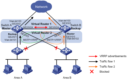
As shown in Figure 2, Switch A and Switch B form two VRRP groups. Implement the following requirements:
· Switch A operates as the master of VRRP group 1 to forward packets from Area A, and Switch B operates as the master of VRRP group 2 to forward packets from Area B. When one of the switches fails, the other switch provides gateway service for both areas.
· When the uplink interface of one switch fails, hosts can access the external network through the other switch.
· To avoid loops between Switch A, Switch B, and the Layer 2 switch, enable MSTP on them, and specify the masters as the root bridges.
Requirements analysis
To make sure one gateway can become the master when the other gateway fails, configure a track entry on the backups in the two VRRP groups to monitor the masters.
To make sure the hosts can access the external network when the uplink interface of the master in a VRRP group fails, configure VRRP tracking on the master. When the uplink interface of the master is down or removed, the master decreases its priority and the backup takes over to forward packets from the hosts.
Software version used
This configuration example was created and verified on S12500-CMW520-R1825P01.
Configuration restrictions and guidelines
When you configure multiple IPv4 VRRP groups, follow these restrictions and guidelines:
· Configure the same virtual IP addresses for each switch in one VRRP group, and make sure the number of virtual IP addresses assigned to them is also the same.
· To avoid affecting network performance, do not create VRRP groups in the VLAN interface on a super VLAN.
· The virtual IP address assigned to the VRRP group must be a legal host address and in the same subnet as the interface IP address. The virtual IP address of a VRRP group cannot be 0.0.0.0, 255.255.255.255, loopback addresses, non-class A/B/C addresses or other illegal IP addresses such as 0.0.0.1.
Configuration procedures
Configuring Switch A
# Configure the source IP address of BFD echo packets as any IP address other than the IP addresses of the interfaces on Switch A.
<SwitchA> system-view
[SwitchA] bfd echo-source-ip 11.11.11.11
# Configure VLAN 101, VLAN 102, and VLAN 103. Configure GigabitEthernet 2/0/24 as a trunk port to allow packets of VLAN 101 and VLAN 102 to pass.
[SwitchA] vlan 101
[SwitchA-vlan101] port Gigabitethernet 2/0/1
[SwitchA-vlan101] quit
[SwitchA] vlan 102
[SwitchA-vlan102] port Gigabitethernet 2/0/3
[SwitchA-vlan102] quit
[SwitchA] vlan 103
[SwitchA-vlan103] port Gigabitethernet 2/0/2
[SwitchA-vlan103] quit
[SwitchA] interface GigabitEthernet2/0/24
[SwitchA-GigabitEthernet2/0/24] undo shutdown
[SwitchA-GigabitEthernet2/0/24] port link-type trunk
[SwitchA-GigabitEthernet2/0/24] undo port trunk permit vlan 1
[SwitchA-GigabitEthernet2/0/24] port trunk permit vlan 101 to 102
[SwitchA-GigabitEthernet2/0/24] port trunk pvid vlan 101
[SwitchA-GigabitEthernet2/0/24] quit
[SwitchA] interface GigabitEthernet 2/0/1
[SwitchA-GigabitEthernet2/0/1] undo shutdown
[SwitchA-GigabitEthernet2/0/1] quit
[SwitchA] interface GigabitEthernet 2/0/2
[SwitchA-GigabitEthernet2/0/2] undo shutdown
[SwitchA-GigabitEthernet2/0/2] quit
[SwitchA] interface GigabitEthernet 2/0/3
[SwitchA-GigabitEthernet2/0/3] undo shutdown
[SwitchA-GigabitEthernet2/0/3] quit
# Configure the uplink interface.
[SwitchA] interface vlan-interface 103
[SwitchA-Vlan-interface103] undo shutdown
[SwitchA-Vlan-interface103] ip address 100.0.0.2 24
[SwitchA-Vlan-interface103] quit
# Create VRRP group 1.
[SwitchA] interface vlan-interface 101
[SwitchA-Vlan-interface101] undo shutdown
[SwitchA-Vlan-interface101] ip address 10.0.0.2 24
[SwitchA-Vlan-interface101] vrrp vrid 1 virtual-ip 10.0.0.1
# Set the priority for VRRP group 1 to 120.
[SwitchA-Vlan-interface101] vrrp vrid 1 priority 120
# Configure uplink interface tracking.
[SwitchA-Vlan-interface101] vrrp vrid 1 track interface Vlan-interface103 reduced 255
[SwitchA-Vlan-interface101] quit
# Create VRRP group 2.
[SwitchA] interface vlan-interface 102
[SwitchA-Vlan-interface102] undo shutdown
[SwitchA-Vlan-interface102] ip address 11.0.0.2 24
[SwitchA-Vlan-interface102] vrrp vrid 1 virtual-ip 11.0.0.1
[SwitchA–Vlan-interface102] vrrp vrid 1 track 1 switchover
# Configure the minimum interval for receiving BFD echo packets on the interface.
[SwitchA–Vlan-interface102] bfd min-echo-receive-interval 10
[SwitchA–Vlan-interface102] bfd detect-multiplier 3
[SwitchA–Vlan-interface102] quit
# Create a track entry.
[SwitchA] track 1 bfd echo interface vlan-interface 101 remote ip 11.0.0.3 local ip 11.0.0.2
# Configure MSTP.
[SwitchA] stp region-configuration
[SwitchA-mst-region] region-name vrrp
[SwitchA-mst-region] instance 1 vlan 101
[SwitchA-mst-region] instance 2 vlan 102
[SwitchA-mst-region] active region-configuration
[SwitchA-mst-region] quit
[SwitchA] stp instance 1 root primary
[SwitchA] stp enable
[SwitchA] interface GigabitEthernet 2/0/2
[SwitchA-GigabitEthernet2/0/2] stp disable
Configuring Switch B
# Configure the source IP address of BFD echo packets as any IP address other than the IP addresses of the interfaces on Switch B.
<SwitchB> system-view
[SwitchB] bfd echo-source-ip 10.10.10.10
# Configure VLAN 101, VLAN 102, and VLAN 103. Configure GigabitEthernet 3/0/24 as a trunk port to allow packets of VLAN 101 and VLAN 102 to pass.
[SwitchB] vlan 101
[SwitchB-vlan101] port Gigabitethernet 3/0/1
[SwitchB-vlan101] quit
[SwitchB] vlan 102
[SwitchB-vlan102] port Gigabitethernet 3/0/3
[SwitchB-vlan102] quit
[SwitchB] vlan 103
[SwitchB-vlan103] port Gigabitethernet 3/0/2
[SwitchB-vlan103] quit
[SwitchB] interface GigabitEthernet3/0/24
[SwitchB-GigabitEthernet3/0/24] port link-type trunk
[SwitchB-GigabitEthernet3/0/24] undo port trunk permit vlan 1
[SwitchB-GigabitEthernet3/0/24] port trunk permit vlan 101 to 102
[SwitchB-GigabitEthernet3/0/24] port trunk pvid vlan 101
[SwitchB-GigabitEthernet3/0/24] quit
[SwitchB] interface GigabitEthernet 3/0/1
[SwitchB-GigabitEthernet3/0/1] undo shutdown
[SwitchB-GigabitEthernet3/0/1] quit
[SwitchB] interface GigabitEthernet 3/0/2
[SwitchB-GigabitEthernet3/0/2] undo shutdown
[SwitchB-GigabitEthernet3/0/2] quit
[SwitchB] interface GigabitEthernet 3/0/3
[SwitchB-GigabitEthernet3/0/3] undo shutdown
[SwitchB-GigabitEthernet3/0/3] quit
# Configure the uplink interface.
[SwitchB] interface vlan-interface 103
[SwitchB-Vlan-interface103] undo shutdown
[SwitchB-Vlan-interface103] ip address 100.0.0.3 24
# Create VRRP group 1.
[SwitchB] interface vlan-interface 101
[SwitchB-Vlan-interface101] undo shutdown
[SwitchB-Vlan-interface101] ip address 10.0.0.3 24
[SwitchB-Vlan-interface101] vrrp vrid 1 virtual-ip 10.0.0.1
[SwitchB–Vlan-interface101] vrrp vrid 1 track 1 switchover
# Configure the minimum interval for receiving BFD echo packets on the interface.
[SwitchB–Vlan-interface101] bfd min-echo-receive-interval 10
[SwitchB–Vlan-interface101] bfd detect-multiplier 3
[SwitchB–Vlan-interface101] quit
# Create a track entry.
[SwitchB] track 1 bfd echo interface vlan-interface 101 remote ip 10.0.0.2 local ip 10.0.0.3
# Create VRRP group 2.
[SwitchB] interface vlan-interface 102
[SwitchB-Vlan-interface102] undo shutdown
[SwitchB-Vlan-interface102] ip address 11.0.0.3 24
[SwitchB-Vlan-interface102] vrrp vrid 1 virtual-ip 11.0.0.1
# Set the priority for VRRP group 2 to 120.
[SwitchB-Vlan-interface102] vrrp vrid 1 priority 120
# Configure uplink interface tracking.
[SwitchB-Vlan-interface102] vrrp vrid 1 track interface Vlan-interface103 reduced 255
[SwitchB-Vlan-interface102] quit
# Configure MSTP.
[SwitchB] stp region-configuration
[SwitchB-mst-region] region-name vrrp
[SwitchB-mst-region] instance 1 vlan 101
[SwitchB-mst-region] instance 2 vlan 102
[SwitchB-mst-region] active region-configuration
[SwitchB-mst-region] quit
[SwitchB] stp instance 2 root primary
[SwitchB] stp enable
[SwitchB] interface GigabitEthernet 3/0/2
[SwitchB-GigabitEthernet3/0/2] stp disable
Configuring the Layer 2 Switch
Configure MSTP on the Layer 2 switch in the same way MSTP is configured on Switch B.
Verifying the configuration
# Verify that the hosts can ping the external network. (Details not shown.)
# Display detailed information about VRRP group 1 on Switch A.
[SwitchA] display vrrp verbose
IPv4 Standby Information:
Run Mode : Standard
Run Method : Virtual MAC
Total number of virtual routers : 2
Interface Vlan-interface101
VRID : 1 Adver Timer : 1
Admin Status : Up State : Master
Config Pri : 120 Running Pri : 120
Preempt Mode : Yes Delay Time : 0
Auth Type : None
Virtual IP : 10.0.0.1
Virtual MAC : 0000-5e00-0101
Master IP : 10.0.0.2
VRRP Track Information:
Track Interface: Vlan103 State : Up Pri Reduced : 255
Interface Vlan-interface102
VRID : 1 Adver Timer : 1
Admin Status : Up State : Backup
Config Pri : 100 Running Pri : 100
Preempt Mode : Yes Delay Time : 0
Auth Type : None
Virtual IP : 11.0.0.1
Master IP : 11.0.0.3
VRRP Track Information:
Track Object : 1 State : Positive Switchover
# Display detailed information about VRRP group 1 on Switch B.
[SwitchB] display vrrp verbose
IPv4 Standby Information:
Run Mode : Standard
Run Method : Virtual MAC
Total number of virtual routers : 2
Interface Vlan-interface101
VRID : 1 Adver Timer : 1
Admin Status : Up State : Backup
Config Pri : 100 Running Pri : 100
Preempt Mode : Yes Delay Time : 0
Auth Type : None
Virtual IP : 10.0.0.1
Master IP : 10.0.0.2
VRRP Track Information:
Track Object : 1 State : Positive Switchover
Interface Vlan-interface102
VRID : 1 Adver Timer : 1
Admin Status : Up State : Master
Config Pri : 120 Running Pri : 120
Preempt Mode : Yes Delay Time : 0
Auth Type : None
Virtual IP : 11.0.0.1
Virtual MAC : 0000-5e00-0101
Master IP : 11.0.0.3
VRRP Track Information:
Track Interface: Vlan103 State : Up Pri Reduced : 255
# Display the MSTP status.
[SwitchA] display stp brief
MSTID Port Role STP State Protection
0 GigabitEthernet2/0/1 DESI FORWARDING NONE
0 GigabitEthernet2/0/3 ROOT FORWARDING NONE
0 GigabitEthernet2/0/24 DESI FORWARDING NONE
1 GigabitEthernet2/0/1 DESI FORWARDING NONE
1 GigabitEthernet2/0/24 DESI FORWARDING NONE
2 GigabitEthernet2/0/3 ALTE DISCARDING NONE
2 GigabitEthernet2/0/24 ROOT FORWARDING NONE
[SwitchB] display stp brief
MSTID Port Role STP State Protection
0 GigabitEthernet3/0/1 DESI FORWARDING NONE
0 GigabitEthernet3/0/3 ROOT FORWARDING NONE
0 GigabitEthernet3/0/24 ALTE DISCARDING NONE
1 GigabitEthernet3/0/1 ALTE DISCARDING NONE
1 GigabitEthernet3/0/24 ROOT FORWARDING NONE
2 GigabitEthernet3/0/3 DESI FORWARDING NONE
2 GigabitEthernet3/0/24 DESI FORWARDING NONE
# When Switch A fails or the uplink VLAN interface under monitoring is down, use the display vrrp verbose command to display detailed information about the VRRP group on Switch B.
[SwitchB] display vrrp verbose
IPv4 Standby Information:
Run Mode : Standard
Run Method : Virtual MAC
Total number of virtual routers : 2
Interface Vlan-interface101
VRID : 1 Adver Timer : 1
Admin Status : Up State : Master
Config Pri : 100 Running Pri : 100
Preempt Mode : Yes Delay Time : 0
Auth Type : None
Virtual IP : 10.0.0.1
Virtual MAC : 0000-5e00-0101
Master IP : 10.0.0.3
VRRP Track Information:
Track Object : 1 State : Positive Switchover
Interface Vlan-interface102
VRID : 1 Adver Timer : 1
Admin Status : Up State : Master
Config Pri : 120 Running Pri : 120
Preempt Mode : Yes Delay Time : 0
Auth Type : None
Virtual IP : 11.0.0.1
Virtual MAC : 0000-5e00-0101
Master IP : 11.0.0.3
VRRP Track Information:
Track Interface: Vlan103 State : Up Pri Reduced : 255
The output shows that Switch B becomes the master of VRRP group 1.
Configuration files
· Switch A:
#
bfd echo-source-ip 11.11.11.11
#
vlan 101 to 103
#
stp region-configuration
region-name vrrp
instance 1 vlan 101
instance 2 vlan 102
active region-configuration
#
stp instance 1 root primary
stp enable
#
interface Vlan-interface101
ip address 10.0.0.2 255.255.255.0
vrrp vrid 1 virtual-ip 10.0.0.1
vrrp vrid 1 priority 120
vrrp vrid 1 track interface Vlan-interface103 reduced 255
#
interface Vlan-interface102
ip address 11.0.0.2 255.255.255.0
bfd min-echo-receive-interval 10
bfd detect-multiplier 3
vrrp vrid 1 virtual-ip 11.0.0.1
vrrp vrid 1 track 1 switchover
#
interface Vlan-interface103
ip address 100.0.0.2 255.255.255.0
#
interface GigabitEthernet2/0/1
port link-mode bridge
port access vlan 101
#
interface GigabitEthernet2/0/2
port link-mode bridge
port access vlan 103
stp disable
#
interface GigabitEthernet2/0/3
port link-mode bridge
port access vlan 102
#
interface GigabitEthernet2/0/24
port link-mode bridge
port link-type trunk
undo port trunk permit vlan 1
port trunk permit vlan 101 to 102
port trunk pvid vlan 101
#
track 1 bfd echo interface vlan-interface 101 remote ip 11.0.0.3 local ip 11.0.0.2
#
· Switch B:
#
bfd echo-source-ip 10.10.10.10
#
vlan 101 to 103
#
stp region-configuration
region-name vrrp
instance 1 vlan 101
instance 2 vlan 102
active region-configuration
#
stp instance 2 root primary
stp enable
#
interface Vlan-interface101
ip address 10.0.0.3 255.255.255.0
bfd min-echo-receive-interval 10
bfd detect-multiplier 3
vrrp vrid 1 virtual-ip 10.0.0.1
vrrp vrid 1 track 1 switchover
#
interface Vlan-interface102
ip address 11.0.0.3 255.255.255.0
vrrp vrid 1 virtual-ip 11.0.0.1
vrrp vrid 1 priority 120
vrrp vrid 1 track interface Vlan-interface103 reduced 255
#
interface Vlan-interface103
ip address 100.0.0.3 255.255.255.0
#
interface GigabitEthernet3/0/1
port link-mode bridge
port access vlan 101
#
interface GigabitEthernet3/0/2
port link-mode bridge
port access vlan 103
stp disable
#
interface GigabitEthernet3/0/3
port link-mode bridge
port access vlan 102
#
interface GigabitEthernet3/0/24
port link-mode bridge
port link-type trunk
undo port trunk permit vlan 1
port trunk permit vlan 101 to 102
port trunk pvid vlan 101
#
track 1 bfd echo interface vlan-interface 101 remote ip 10.0.0.2 local ip 10.0.0.3
#
Example: Configuring IPv4 VRRP load balancing mode
Network requirements
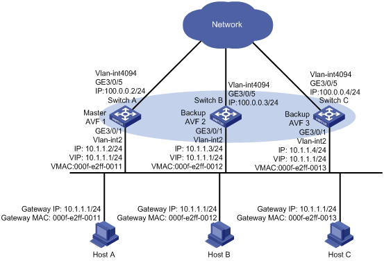
As shown in Figure 3, Switch A, Switch B, and Switch C form a load-balanced VRRP group and use the virtual IP address 10.1.1.1/24 to provide gateway service. Implement the following requirements:
· Switch A operates as the master of the VRRP group. When one of the switches in the VRRP group fails, the hosts can access the external network through other switches.
· Packets from the hosts are forwarded by different switches to reduce the burden of the master.
· When the upstream link of the active virtual forwarder (AVF) fails, the AVF can notify a listening virtual forwarder (LVF) to take over.
Requirements analysis
For the AVF to notify an LVF to take over its role when the upstream link of the AVF fails, configure VF tracking on each gateway to monitor the uplink. Use BFD to monitor the upstream link state of the VF owner, and use the tracking function to establish the collaboration between the VFs and BFD. When the upstream link fails, the state of the track entry changes to Negative, and the weights of the VFs (including the AVF) on the switch decrease by a specified value. The corresponding LVF with a higher priority on another switch becomes the AVF and forwards packets.
Software version used
This configuration example was created and verified on S12500-CMW520-R1825P01.
Configuration restrictions and guidelines
When you configure IPv4 VRRP load balancing mode, follow these restrictions and guidelines:
· To avoid affecting network performance, do not create VRRP groups in the VLAN interface on a super VLAN.
· In load balancing mode, the virtual IP address of a VRRP group can be any unassigned IP address of the subnet where the VRRP group resides, rather than the IP address of any interface in the VRRP group. No IP address owner can exist in a VRRP group.
· The virtual IP address assigned to the VRRP group must be a legal host address and in the same subnet as the interface IP address. The virtual IP address of a VRRP group cannot be 0.0.0.0, 255.255.255.255, loopback addresses, non-class A/B/C addresses or other illegal IP addresses such as 0.0.0.1.
· The virtual IP addresses of a VRRP group and the IP address of the interface where the VRRP group is configured must be in the same subnet. Otherwise, hosts on the subnet cannot access external networks.
Configuration procedures
Configuring Switch A
# Configure VLAN 2.
<SwitchA> system-view
[SwitchA] vlan 2
[SwitchA-vlan2] port Gigabitethernet 3/0/1
[SwitchA-vlan2] quit
[SwitchA] interface GigabitEthernet 3/0/1
[SwitchA-GigabitEthernet3/0/1] undo shutdown
[SwitchA-GigabitEthernet3/0/1] quit
# Configure VLAN 4094.
[SwitchA] vlan 4094
[SwitchA-vlan4094] port Gigabitethernet 3/0/5
[SwitchA-vlan4094] quit
[SwitchA] interface GigabitEthernet 3/0/5
[SwitchA-GigabitEthernet3/0/5] undo shutdown
[SwitchA-GigabitEthernet3/0/5] quit
# Configure VRRP to work in the load balancing mode.
[SwitchA] vrrp mode load-balance
# Create VRRP group 1, and set the virtual IP address for the group to 10.1.1.1.
[SwitchA] interface vlan-interface 2
[SwitchA-Vlan-interface2] ip address 10.1.1.2 24
[SwitchA-Vlan-interface2] vrrp vrid 1 virtual-ip 10.1.1.1
# Set the priority of Switch A in VRRP group 1 to 120.
[SwitchA-Vlan-interface2] vrrp vrid 1 priority 120
# Configure VRRP tracking for the VF.
[SwitchA-Vlan-interface2] vrrp vrid 1 weight track 1 reduced 255
[SwitchA–Vlan-interface2] undo shutdown
[SwitchA-Vlan-interface2] quit
# Configure the uplink interface, BFD parameters, and the track entry.
[SwitchA] bfd echo-source-ip 45.45.45.45
[SwitchA] track 1 bfd echo interface Vlan-interface4094 remote ip 100.0.0.1 local ip 100.0.0.2
[SwitchA] interface vlan-interface 4094
[SwitchA-Vlan-interface4094] ip address 100.0.0.2 24
[SwitchA-Vlan-interface4094] bfd min-echo-receive-interval 100
[SwitchA-Vlan-interface4094] bfd detect-multiplier 3
[SwitchA–Vlan-interface4094] undo shutdown
Configuring Switch B
# Configure VLAN 2.
<SwitchB> system-view
[SwitchB] vlan 2
[SwitchB-vlan2] port Gigabitethernet 3/0/1
[SwitchB-vlan2] quit
[SwitchB] interface GigabitEthernet 3/0/1
[SwitchB-GigabitEthernet3/0/1] undo shutdown
[SwitchB-GigabitEthernet3/0/1] quit
# Configure VLAN 4094.
[SwitchB] vlan 4094
[SwitchB-vlan4094] port Gigabitethernet 3/0/5
[SwitchB-vlan4094] quit
[SwitchB] interface GigabitEthernet 3/0/5
[SwitchB-GigabitEthernet3/0/5] undo shutdown
[SwitchB-GigabitEthernet3/0/5] quit
# Configure VRRP to work in the load balancing mode.
[SwitchB] vrrp mode load-balance
# Create VRRP group 1, and set the virtual IP address for the group to 10.1.1.1.
[SwitchB] interface vlan-interface 2
[SwitchB-Vlan-interface2] ip address 10.1.1.3 24
[SwitchB-Vlan-interface2] vrrp vrid 1 virtual-ip 10.1.1.1
# Set the priority of Switch A in VRRP group 1 to 110.
[SwitchB-Vlan-interface2] vrrp vrid 1 priority 110
# Configure VRRP tracking for the VF.
[SwitchB-Vlan-interface2] vrrp vrid 1 weight track 1 reduced 255
[SwitchB–Vlan-interface2] undo shutdown
[SwitchB-Vlan-interface2] quit
# Configure the uplink interface, BFD parameters, and the track entry.
[SwitchB] bfd echo-source-ip 56.56.56.56
[SwitchB] track 1 bfd echo interface Vlan-interface4094 remote ip 100.0.0.1 local ip 100.0.0.3
[SwitchB] interface vlan-interface 4094
[SwitchB-Vlan-interface4094] ip address 100.0.0.3 24
[SwitchB-Vlan-interface4094] bfd min-echo-receive-interval 100
[SwitchB-Vlan-interface4094] bfd detect-multiplier 3
[SwitchB–Vlan-interface4094] undo shutdown
Configuring Switch C
# Configure VLAN 2.
<SwitchC> system-view
[SwitchC] vlan 2
[SwitchC-vlan2] port Gigabitethernet 3/0/1
[SwitchC-vlan2] quit
[SwitchC] interface GigabitEthernet 3/0/1
[SwitchC-GigabitEthernet3/0/1] undo shutdown
[SwitchC-GigabitEthernet3/0/1] quit
# Configure VLAN 4094.
[SwitchC] vlan 4094
[SwitchC-vlan4094] port Gigabitethernet 3/0/5
[SwitchC-vlan4094] quit
[SwitchC] interface GigabitEthernet 3/0/5
[SwitchC-GigabitEthernet3/0/5] undo shutdown
[SwitchC-GigabitEthernet3/0/5] quit
# Configure VRRP to work in the load balancing mode.
[SwitchC] vrrp mode load-balance
# Create VRRP group 1, and set the virtual IP address for the group to 10.1.1.1.
[SwitchC] interface vlan-interface 2
[SwitchC-Vlan-interface2] ip address 10.1.1.4 24
[SwitchC-Vlan-interface2] vrrp vrid 1 virtual-ip 10.1.1.1
# Configure VRRP tracking for the VF.
[SwitchC-Vlan-interface2] vrrp vrid 1 weight track 1 reduced 255
[SwitchC-Vlan-interface2] undo shutdown
[SwitchC-Vlan-interface2] quit
# Configure the uplink interface, BFD parameters, and the track entry.
[SwitchC] bfd echo-source-ip 67.67.67.67
[SwitchC] track 1 bfd echo interface Vlan-interface4094 remote ip 100.0.0.1 local ip 100.0.0.4
[SwitchC] interface vlan-interface 4094
[SwitchC-Vlan-interface4094] ip address 100.0.0.4 24
[SwitchC-Vlan-interface4094] bfd min-echo-receive-interval 100
[SwitchC-Vlan-interface4094] bfd detect-multiplier 3
[SwitchC-Vlan-interface4094] undo shutdown
Verifying the configuration
# Verify that Host A, Host B, and Host C can access external networks. (Details not shown.)
# Display detailed information about VRRP group 1 on Switch A.
[SwitchA] display vrrp verbose
IPv4 Virtual Router Information:
Running Mode : Load Balance
Total number of virtual routers : 1
Interface Vlan-interface2
VRID : 1 Adver Timer : 1
Admin Status : Up State : Master
Config Pri : 120 Running Pri : 120
Preempt Mode : Yes Delay Time : 0
Auth Type : None
Virtual IP : 10.1.1.1
Master IP : 10.1.1.2
Forwarder Information: 3 Forwarders 1 Active
Config Weight : 255
Running Weight : 255
Forwarder 01
State : Active
Virtual MAC : 000f-e2ff-0011 (Owner)
Owner ID : 6697-1250-0100
Priority : 255
Active : local
Forwarder 02
State : Listening
Virtual MAC : 000f-e2ff-0012 (Learnt)
Owner ID : 00e0-6405-3100
Priority : 127
Active : 10.1.1.3
Forwarder 03
State : Listening
Virtual MAC : 000f-e2ff-0013 (Learnt)
Owner ID : 0001-0002-0103
Priority : 127
Active : 10.1.1.4
Forwarder Weight Track Information:
Track Object : 1 State : Positive Weight Reduced : 255
# Display detailed information about VRRP group 1 on Switch B.
[SwitchB] display vrrp verbose
IPv4 Virtual Router Information:
Running Mode : Load Balance
Total number of virtual routers : 1
Interface Vlan-interface2
VRID : 1 Adver Timer : 1
Admin Status : Up State : Backup
Config Pri : 110 Running Pri : 110
Preempt Mode : Yes Delay Time : 0
Auth Type : None
Virtual IP : 10.1.1.1
Master IP : 10.1.1.2
Forwarder Information: 3 Forwarders 1 Active
Config Weight : 255
Running Weight : 255
Forwarder 01
State : Listening
Virtual MAC : 000f-e2ff-0011 (Learnt)
Owner ID : 6697-1250-0100
Priority : 127
Active : 10.1.1.2
Forwarder 02
State : Active
Virtual MAC : 000f-e2ff-0012 (Owner)
Owner ID : 00e0-6405-3100
Priority : 255
Active : local
Forwarder 03
State : Listening
Virtual MAC : 000f-e2ff-0013 (Learnt)
Owner ID : 0001-0002-0103
Priority : 127
Active : 10.1.1.4
Forwarder Weight Track Information:
Track Object : 1 State : Positive Weight Reduced : 255
# Display detailed information about VRRP group 1 on Switch C.
[SwitchC] display vrrp verbose
IPv4 Virtual Router Information:
Running Mode : Load Balance
Total number of virtual routers : 1
Interface Vlan-interface2
VRID : 1 Adver Timer : 1
Admin Status : Up State : Backup
Config Pri : 100 Running Pri : 100
Preempt Mode : Yes Delay Time : 0
Auth Type : None
Virtual IP : 10.1.1.1
Master IP : 10.1.1.2
Forwarder Information: 3 Forwarders 1 Active
Config Weight : 255
Running Weight : 255
Forwarder 01
State : Listening
Virtual MAC : 000f-e2ff-0011 (Learnt)
Owner ID : 6697-1250-0100
Priority : 127
Active : 10.1.1.2
Forwarder 02
State : Listening
Virtual MAC : 000f-e2ff-0012 (Learnt)
Owner ID : 00e0-6405-3100
Priority : 127
Active : 10.1.1.3
Forwarder 03
State : Active
Virtual MAC : 000f-e2ff-0013 (Owner)
Owner ID : 0001-0002-0103
Priority : 255
Active : local
Forwarder Weight Track Information:
Track Object : 1 State : Positive Weight Reduced : 255
The output shows that in VRRP group 1, Switch A is the master and Switch B and Switch C are the backups. An active VF and two listening VFs exist on each switch.
# When Switch A fails, use the display vrrp verbose command to display detailed information about the VRRP group on Switch C.
[SwitchC] display vrrp verbose
IPv4 Virtual Router Information:
Running Mode : Load Balance
Total number of virtual routers : 1
Interface Vlan-interface2
VRID : 1 Adver Timer : 1
Admin Status : Up State : Backup
Config Pri : 100 Running Pri : 100
Preempt Mode : Yes Delay Time : 0
Auth Type : None
Virtual IP : 10.1.1.1
Master IP : 10.1.1.3
Forwarder Information: 3 Forwarders 2 Active
Config Weight : 255
Running Weight : 255
Forwarder 01
State : Active
Virtual MAC : 000f-e2ff-0011 (Take Over)
Owner ID : 6697-1250-0100
Priority : 85
Active : local
Redirect Time : 588 secs
Time-out Time : 1788 secs
Forwarder 02
State : Listening
Virtual MAC : 000f-e2ff-0012 (Learnt)
Owner ID : 00e0-6405-3100
Priority : 85
Active : 10.1.1.3
Forwarder 03
State : Active
Virtual MAC : 000f-e2ff-0013 (Owner)
Owner ID : 0001-0002-0103
Priority : 255
Active : local
Forwarder Weight Track Information:
Track Object : 1 State : Positive Weight Reduced : 255
The output shows that Switch B becomes the master after Switch A fails; Switch C becomes an AVF with virtual MAC address 000f-e2ff-0011 mapped to it and forwards packets sent by Host A.
Configuration files
· Switch A:
#
vlan 2
#
vlan 4094
#
vrrp mode load-balance
#
bfd echo-source-ip 45.45.45.45
#
interface Vlan-interface2
ip address 10.1.1.2 255.255.255.0
vrrp vrid 1 virtual-ip 10.1.1.1
vrrp vrid 1 priority 120
vrrp vrid 1 weight track 1 reduced 255
#
interface Vlan-interface4094
ip address 100.0.0.2 255.255.255.0
bfd min-echo-receive-interval 100
bfd detect-multiplier 3
#
interface GigabitEthernet3/0/1
port access vlan 2
#
#
interface GigabitEthernet3/0/5
port access vlan 4094
#
track 1 bfd echo interface Vlan-interface4094 remote ip 100.0.0.1 local ip 100.0.0.2
#
· Switch B:
#
vlan 2
#
vlan 4094
#
vrrp mode load-balance
#
bfd echo-source-ip 56.56.56.56
#
interface Vlan-interface2
ip address 10.1.1.3 255.255.255.0
vrrp vrid 1 virtual-ip 10.1.1.1
vrrp vrid 1 priority 110
vrrp vrid 1 weight track 1 reduced 255
#
interface Vlan-interface4094
ip address 100.0.0.3 255.255.255.0
bfd min-echo-receive-interval 100
bfd detect-multiplier 3
#
interface GigabitEthernet3/0/1
port access vlan 2
#
#
interface GigabitEthernet3/0/5
port access vlan 4094
#
track 1 bfd echo interface Vlan-interface4094 remote ip 100.0.0.1 local ip 100.0.0.3
#
· Switch C:
#
vlan 2
#
vlan 4094
#
vrrp mode load-balance
#
bfd echo-source-ip 67.67.67.67
#
interface Vlan-interface2
ip address 10.1.1.4 255.255.255.0
vrrp vrid 1 virtual-ip 10.1.1.1
vrrp vrid 1 weight track 1 reduced 255
#
interface Vlan-interface4094
ip address 100.0.0.4 255.255.255.0
bfd min-echo-receive-interval 100
bfd detect-multiplier 3
#
interface GigabitEthernet3/0/1
port access vlan 2
#
#
interface GigabitEthernet3/0/5
port access vlan 4094
#
track 1 bfd echo interface Vlan-interface4094 remote ip 100.0.0.1 local ip 100.0.0.4
#
Example: Configuring a single IPv6 VRRP group
Network requirements
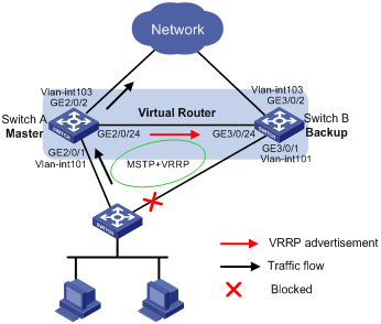
As shown in Figure 4, configure a VRRP group on Switch A and Switch B as the gateway for the hosts, and implement the following requirements:
· Switch A operates as the master to forward packets from the hosts to the external network. When Switch A fails, Switch B takes over to forward packets for the hosts.
· When the uplink interface of Switch A fails, hosts can access the external network through Switch B.
· To avoid loops between Switch A, Switch B, and the Layer 2 switch, enable MSTP on them, and specify the master as the root bridge.
Requirements analysis
To make sure Switch B can become the master when Switch A fails, configure a track entry on Switch B to monitor Switch A.
To make sure hosts can access the external network when the uplink interface of Switch A fails, configure VRRP tracking on Switch A. When the uplink interface of Switch A is down or removed, Switch A decreases its priority and Switch B takes over to forward packets from the hosts.
Software version used
This configuration example was created and verified on S12500-CMW520-R1825P01.
Configuration restrictions and guidelines
When you configure a single IPv6 VRRP group, follow these restrictions and guidelines:
· To make sure H3C S12500 switches can forward IPv6 packets correctly, enable IPv6 packet forwarding first. (This function is disabled by default.)
· Configure the same virtual IP addresses for each switch in one VRRP group, and make sure the number of virtual IP addresses assigned to them is also the same.
· To avoid affecting network performance, do not create VRRP groups in the VLAN interface on a super VLAN.
Configuration procedures
Configuring Switch A
# Enable IPv6 packet forwarding.
<SwitchA> system-view
[SwitchA] ipv6
# Configure VLAN 101 and VLAN 103.
[SwitchA] vlan 101
[SwitchA-vlan101] port Gigabitethernet 2/0/1
[SwitchA-vlan101] port Gigabitethernet 2/0/24
[SwitchA-vlan101] quit
[SwitchA] vlan 103
[SwitchA-vlan103] port Gigabitethernet 2/0/2
[SwitchA-vlan103] quit
[SwitchA] interface GigabitEthernet 2/0/1
[SwitchA-GigabitEthernet2/0/1] undo shutdown
[SwitchA-GigabitEthernet2/0/1] quit
[SwitchA] interface GigabitEthernet 2/0/2
[SwitchA-GigabitEthernet2/0/2] undo shutdown
[SwitchA-GigabitEthernet2/0/2] quit
[SwitchA] interface GigabitEthernet 2/0/24
[SwitchA-GigabitEthernet2/0/24] undo shutdown
[SwitchA-GigabitEthernet2/0/24] quit
# Configure the uplink interface.
[SwitchA] interface vlan-interface 103
[SwitchA-Vlan-interface103] undo shutdown
[SwitchA-Vlan-interface103] ipv6 address 2003::2 64
[SwitchA-Vlan-interface103] quit
# Create VRRP group 1.
[SwitchA] interface vlan-interface 101
[SwitchA-Vlan-interface101] undo shutdown
[SwitchA-Vlan-interface101] ipv6 address 2001::2 64
[SwitchA-Vlan-interface101] vrrp ipv6 vrid 1 virtual-ip FE80::1 link-local
[SwitchA-Vlan-interface101] vrrp ipv6 vrid 1 virtual-ip 2001::1
# Configure an IP address for VLAN-interface 101. This interface is configured for BFD implementation.
[SwitchA-Vlan-interface101] ip address 10.0.0.2 24
# Set the priority of Switch A in VRRP group 1 to 120.
[SwitchA-Vlan-interface101] vrrp ipv6 vrid 1 priority 120
# Configure uplink interface tracking.
[SwitchA-Vlan-interface101] vrrp ipv6 vrid 1 track interface Vlan-interface103 reduced 255
[SwitchA-Vlan-interface101] quit
# Configure MSTP.
[SwitchA] stp region-configuration
[SwitchA-mst-region] region-name vrrp
[SwitchA-mst-region] instance 1 vlan 101
[SwitchA-mst-region] active region-configuration
[SwitchA-mst-region] quit
[SwitchA] stp instance 1 root primary
[SwitchA] stp enable
[SwitchA] interface GigabitEthernet 2/0/2
[SwitchA-GigabitEthernet2/0/2] stp disable
Configuring Switch B
# Enable IPv6 packet forwarding.
<SwitchB> system-view
[SwitchB] ipv6
# Configure the source IP address of BFD echo packets as any IP address other than the IP addresses of the interfaces on Switch B.
[SwitchB] bfd echo-source-ip 10.10.10.10
# Configure VLAN 101 and VLAN 103.
[SwitchB] vlan 101
[SwitchB-vlan101] port Gigabitethernet 3/0/1
[SwitchB-vlan101] port Gigabitethernet 3/0/24
[SwitchB-vlan101] quit
[SwitchB] vlan 103
[SwitchB-vlan103] port Gigabitethernet 3/0/2
[SwitchB-vlan103] quit
[SwitchB] interface GigabitEthernet 3/0/1
[SwitchB-GigabitEthernet3/0/1] undo shutdown
[SwitchB-GigabitEthernet3/0/1] quit
[SwitchB] interface GigabitEthernet 3/0/2
[SwitchB-GigabitEthernet3/0/2] undo shutdown
[SwitchB-GigabitEthernet3/0/2] quit
[SwitchB] interface GigabitEthernet 3/0/24
[SwitchB-GigabitEthernet3/0/24] undo shutdown
[SwitchB-GigabitEthernet3/0/24] quit
# Configure the uplink interface.
[SwitchB] interface vlan-interface 103
[SwitchB-Vlan-interface103] undo shutdown
[SwitchB-Vlan-interface103] ipv6 address 2003::3 64
[SwitchB-Vlan-interface103] quit
# Create VRRP group 1.
[SwitchB] interface vlan-interface 101
[SwitchB-Vlan-interface101] undo shutdown
[SwitchB-Vlan-interface101] ipv6 address 2001::3 64
[SwitchB-Vlan-interface101] vrrp ipv6 vrid 1 virtual-ip FE80::1 link-local
[SwitchB-Vlan-interface101] vrrp ipv6 vrid 1 virtual-ip 2001::1
[SwitchB–Vlan-interface101] vrrp ipv6 vrid 1 track 1 switchover
# Configure an IP address for VLAN-interface 101. This interface is configured for BFD implementation.
[SwitchB-Vlan-interface101] ip address 10.0.0.3 24
# Configure the minimum interval for receiving BFD echo packets on the interface.
[SwitchB–Vlan-interface101] bfd min-echo-receive-interval 10
[SwitchB–Vlan-interface101] bfd detect-multiplier 3
[SwitchB–Vlan-interface101] quit
# Create a track entry.
[SwitchB] track 1 bfd echo interface vlan-interface 101 remote ip 10.0.0.2 local ip 10.0.0.3
# Configure MSTP.
[SwitchB] stp region-configuration
[SwitchB-mst-region] region-name vrrp
[SwitchB-mst-region] instance 1 vlan 101
[SwitchB-mst-region] active region-configuration
[SwitchB-mst-region] quit
[SwitchB] stp enable
[SwitchB] interface GigabitEthernet 3/0/2
[SwitchB-GigabitEthernet3/0/2] stp disable
Configuring the Layer 2 Switch
Configure MSTP on the Layer 2 switch in the way MSTP is configured on Switch B.
Verifying the configuration
# Verify that the hosts can ping the external network. (Details not shown.)
# Display detailed information about VRRP group 1 on Switch A.
[SwitchA] display vrrp ipv6 verbose
IPv6 Standby Information:
Run Mode : Standard
Run Method : Virtual MAC
Total number of virtual routers : 1
Interface Vlan-interface101
VRID : 1 Adver Timer : 100
Admin Status : Up State : Master
Config Pri : 120 Running Pri : 120
Preempt Mode : Yes Delay Time : 0
Auth Type : None
Virtual IP : FE80::1
2001::1
Virtual MAC : 0000-5e00-0201
Master IP : FE80::2E0:64FF:FE05:3100
VRRP Track Information:
Track Interface: Vlan103 State : Up Pri Reduced : 255
# Display detailed information about VRRP group 1 on Switch B.
[SwitchB] display vrrp ipv6 verbose
IPv6 Standby Information:
Run Mode : Standard
Run Method : Virtual MAC
Total number of virtual routers : 1
Interface Vlan-interface101
VRID : 1 Adver Timer : 100
Admin Status : Up State : Backup
Config Pri : 100 Running Pri : 100
Preempt Mode : Yes Delay Time : 0
Auth Type : None
Virtual IP : FE80::1
2001::1
Master IP : FE80::2E0:64FF:FE05:3100
VRRP Track Information:
Track Object : 1 State : Positive Switchover
# Display the MSTP status on the Layer 2 switch.
[SwitchB]display stp instance 1 brief
MSTID Port Role STP State Protection
1 GigabitEthernet3/0/1 ALTE DISCARDING NONE
1 GigabitEthernet3/0/24 ROOT FORWARDING NONE
The output shows that the interface connecting to the backup device is blocked.
# When Switch A fails or the uplink VLAN interface under monitoring is down, use the display vrrp ipv6 verbose command to display detailed information about the VRRP group on Switch B.
[SwitchB] display vrrp ipv6 verbose
IPv6 Standby Information:
Run Mode : Standard
Run Method : Virtual MAC
Total number of virtual routers : 1
Interface Vlan-interface101
VRID : 1 Adver Timer : 100
Admin Status : Up State : Master
Config Pri : 100 Running Pri : 100
Preempt Mode : Yes Delay Time : 0
Auth Type : None
Virtual IP : FE80::1
2001::1
Virtual MAC : 0000-5e00-0201
Master IP : FE80::6697:12FF:FE50:100
VRRP Track Information:
Track Object : 1 State : Negative Switchover
The output shows that Switch B becomes the master of VRRP group 1.
Configuration files
· Switch A:
#
ipv6
#
vlan 101
#
vlan 103
#
stp region-configuration
region-name vrrp
instance 1 vlan 101
active region-configuration
#
stp instance 1 root primary
stp enable
#
interface Vlan-interface101
ipv6 address 2001::2/64
ip address 10.0.0.2 255.255.255.0
vrrp ipv6 vrid 1 virtual-ip FE80::1 link-local
vrrp ipv6 vrid 1 virtual-ip 2001::1
vrrp ipv6 vrid 1 priority 120
vrrp ipv6 vrid 1 track interface Vlan-interface103 reduced 255
#
interface Vlan-interface103
ipv6 address 2003::2/64
#
interface GigabitEthernet2/0/1
port link-mode bridge
port access vlan 101
#
interface GigabitEthernet2/0/2
port link-mode bridge
port access vlan 103
stp disable
#
interface GigabitEthernet2/0/24
port link-mode bridge
port access vlan 101
#
· Switch B:
#
ipv6
#
bfd echo-source-ip 10.10.10.10
#
vlan 101
#
vlan 103
#
stp region-configuration
region-name vrrp
instance 1 vlan 101
active region-configuration
#
stp instance 1 root primary
stp enable
#
interface Vlan-interface101
ipv6 address 2001::3/64
ip address 10.0.0.3 255.255.255.0
bfd min-echo-receive-interval 10
bfd detect-multiplier 3
vrrp ipv6 vrid 1 virtual-ip FE80::1 link-local
vrrp ipv6 vrid 1 virtual-ip 2001::1
vrrp ipv6 vrid 1 track 1 switchover
#
interface Vlan-interface103
ipv6 address 2003::3/64
#
interface GigabitEthernet3/0/1
port link-mode bridge
port access vlan 101
#
interface GigabitEthernet3/0/24
port link-mode bridge
port access vlan 101
#
interface GigabitEthernet3/0/2
port link-mode bridge
port access vlan 103
stp disable
#
track 1 bfd echo interface vlan-interface 101 remote ip 10.0.0.2 local ip 10.0.0.3
#
Example: Configuring multiple IPv6 VRRP groups
Network requirements
As shown in Figure 5, Switch A and Switch B form two VRRP groups. Implement the following requirements:
· Switch A operates as the master of VRRP group 1 to forward packets from Area A, and Switch B operates as the master of VRRP group 2 to forward packets from Area B. When one of the switches fails, the other switch provides gateway service for both areas.
· When the uplink interface of one switch fails, hosts can access the external network through the other switch.
· To avoid loops between Switch A, Switch B, and the Layer 2 switch, enable MSTP on them, and specify the masters as the root bridges.
Requirements analysis
To make sure one gateway can become the master when the other gateway fails, configure a track entry on the backups in the two VRRP groups to monitor the masters.
To make sure the hosts can access the external network when the uplink interface of the master in a VRRP group fails, configure VRRP tracking on the master. When the uplink interface of the master is down or removed, the master decreases its priority and the backup takes over to forward packets from the hosts.
Software version used
This configuration example was created and verified on S12500-CMW520-R1825P01.
Configuration restrictions and guidelines
When you configure multiple IPv6 VRRP groups, follow these restrictions and guidelines:
· To make sure H3C S12500 switches can forward IPv6 packets correctly, enable IPv6 packet forwarding first. (This function is disabled by default.)
· Configure the same virtual IP addresses for each switch in one VRRP group, and make sure the number of virtual IP addresses assigned to them is also the same.
· To avoid affecting network performance, do not create VRRP groups in the VLAN interface on a super VLAN.
Configuration procedures
Configuring Switch A
# Enable IPv6 packet forwarding.
<SwitchA> system-view
[SwitchA] ipv6
# Configure the source IP address of BFD echo packets as any IP address other than the IP addresses of the interfaces on Switch A.
[SwitchA] bfd echo-source-ip 11.11.11.11
# Configure VLAN 101, VLAN 102, and VLAN 103. Configure GigabitEthernet 2/0/24 as a trunk port to allow packets of VLAN 101 and VLAN 102 to pass.
[SwitchA] vlan 101
[SwitchA-vlan101] port Gigabitethernet 2/0/1
[SwitchA-vlan101] quit
[SwitchA] vlan 102
[SwitchA-vlan102] port Gigabitethernet 2/0/3
[SwitchA-vlan102] quit
[SwitchA] vlan 103
[SwitchA-vlan103] port Gigabitethernet 2/0/2
[SwitchA-vlan103] quit
[SwitchA] interface GigabitEthernet 2/0/1
[SwitchA-GigabitEthernet3/0/1] undo shutdown
[SwitchA-GigabitEthernet3/0/1] quit
[SwitchA] interface GigabitEthernet 2/0/2
[SwitchA-GigabitEthernet2/0/2] undo shutdown
[SwitchA-GigabitEthernet2/0/2] quit
[SwitchA] interface GigabitEthernet 2/0/3
[SwitchA-GigabitEthernet2/0/3] undo shutdown
[SwitchA-GigabitEthernet2/0/3] quit
[SwitchA] interface GigabitEthernet2/0/24
[SwitchA-GigabitEthernet2/0/24] undo shutdown
[SwitchA-GigabitEthernet2/0/24] port link-type trunk
[SwitchA-GigabitEthernet2/0/24] undo port trunk permit vlan 1
[SwitchA-GigabitEthernet2/0/24] port trunk permit vlan 101 to 102
[SwitchA-GigabitEthernet2/0/24] port trunk pvid vlan 101
[SwitchA-GigabitEthernet2/0/24] quit
# Configure the uplink interface.
[SwitchA] interface vlan-interface 103
[SwitchA-Vlan-interface103] undo shutdown
[SwitchA-Vlan-interface103] ipv6 address 2003::2 64
[SwitchA-Vlan-interface103] quit
# Create VRRP group 1.
[SwitchA] interface vlan-interface 101
[SwitchA-Vlan-interface101] undo shutdown
[SwitchA-Vlan-interface101] ipv6 address 2001::2 64
[SwitchA-Vlan-interface101] vrrp ipv6 vrid 1 virtual-ip FE80::1 link-local
[SwitchA-Vlan-interface101] vrrp ipv6 vrid 1 virtual-ip 2001::1
# Set the priority for VRRP group 1 to 120.
[SwitchA-Vlan-interface101] vrrp ipv6 vrid 1 priority 120
# Configure uplink interface tracking.
[SwitchA-Vlan-interface101] vrrp ipv6 vrid 1 track interface Vlan-interface103 reduced 255
[SwitchA-Vlan-interface101] quit
# Create VRRP group 2.
[SwitchA] interface vlan-interface 102
[SwitchA-Vlan-interface102] undo shutdown
[SwitchA-Vlan-interface102] ipv6 address 2002::2 64
[SwitchA-Vlan-interface102] vrrp ipv6 vrid 1 virtual-ip FE80::1 link-local
[SwitchA-Vlan-interface102] vrrp ipv6 vrid 1 virtual-ip 2002::1
[SwitchA–Vlan-interface102] vrrp ipv6 vrid 1 track 1 switchover
# Configure an IP address for VLAN-interface 102. This interface is configured for BFD implementation.
[SwitchA-Vlan-interface102] ip address 11.0.0.2 24
# Configure the minimum interval for receiving BFD echo packets on the interface.
[SwitchA–Vlan-interface102] bfd min-echo-receive-interval 10
[SwitchA–Vlan-interface102] bfd detect-multiplier 3
[SwitchA–Vlan-interface102] quit
# Create a track entry.
[SwitchA] track 1 bfd echo interface vlan-interface 101 remote ip 11.0.0.3 local ip 11.0.0.2
# Configure MSTP.
[SwitchA] stp region-configuration
[SwitchA-mst-region] region-name vrrp
[SwitchA-mst-region] instance 1 vlan 101
[SwitchA-mst-region] instance 2 vlan 102
[SwitchA-mst-region] active region-configuration
[SwitchA-mst-region] quit
[SwitchA] stp instance 1 root primary
[SwitchA] stp enable
[SwitchA] interface GigabitEthernet 2/0/2
[SwitchA-GigabitEthernet2/0/2] stp disable
Configuring Switch B
# Enable IPv6 packet forwarding.
<SwitchB> system-view
[SwitchB] ipv6
# Configure the source IP address of BFD echo packets as any IP address other than the IP addresses of the interfaces on Switch B.
[SwitchB] bfd echo-source-ip 10.10.10.10
# Configure VLAN 101, VLAN 102, and VLAN 103. Configure GigabitEthernet 3/0/24 as a trunk port to allow packets of VLAN 101 and VLAN 102 to pass.
[SwitchB] vlan 101
[SwitchB-vlan101] port Gigabitethernet 3/0/1
[SwitchB-vlan101] quit
[SwitchB] vlan 102
[SwitchB-vlan102] port Gigabitethernet 3/0/3
[SwitchB-vlan102] quit
[SwitchB] vlan 103
[SwitchB-vlan103] port Gigabitethernet 3/0/2
[SwitchB-vlan103] quit
[SwitchB] interface GigabitEthernet 3/0/1
[SwitchB-GigabitEthernet3/0/1] undo shutdown
[SwitchB-GigabitEthernet3/0/1] quit
[SwitchB] interface GigabitEthernet 3/0/2
[SwitchB-GigabitEthernet3/0/2] undo shutdown
[SwitchB-GigabitEthernet3/0/2] quit
[SwitchB] interface GigabitEthernet 3/0/3
[SwitchB-GigabitEthernet3/0/3] undo shutdown
[SwitchB-GigabitEthernet3/0/3] quit
[SwitchB] interface GigabitEthernet3/0/24
[SwitchB-GigabitEthernet3/0/24] undo shutdown
[SwitchB-GigabitEthernet3/0/24] port link-type trunk
[SwitchB-GigabitEthernet3/0/24] undo port trunk permit vlan 1
[SwitchB-GigabitEthernet3/0/24] port trunk permit vlan 101 to 102
[SwitchB-GigabitEthernet3/0/24] port trunk pvid vlan 101
[SwitchB-GigabitEthernet3/0/24] quit
# Configure the uplink interface.
[SwitchB] interface vlan-interface 103
[SwitchB-Vlan-interface103] undo shutdown
[SwitchB-Vlan-interface103] ipv6 address 2003::3 64
[SwitchB-Vlan-interface103] quit
# Create VRRP group 1.
[SwitchB] interface vlan-interface 101
[SwitchB-Vlan-interface101] undo shutdown
[SwitchB-Vlan-interface101] ipv6 address 2001::3 64
[SwitchB-Vlan-interface101] vrrp ipv6 vrid 1 virtual-ip FE80::1 link-local
[SwitchB-Vlan-interface101] vrrp ipv6 vrid 1 virtual-ip 2001::1
[SwitchB–Vlan-interface101] vrrp ipv6 vrid 1 track 1 switchover
# Configure an IP address for VLAN-interface 101. This interface is configured for BFD implementation.
[SwitchB-Vlan-interface101] ip address 10.0.0.3 24
# Configure the minimum interval for receiving BFD echo packets on the interface.
[SwitchB–Vlan-interface101] bfd min-echo-receive-interval 10
[SwitchB–Vlan-interface101] bfd detect-multiplier 3
[SwitchB–Vlan-interface101] quit
# Create a track entry.
[SwitchB] track 1 bfd echo interface vlan-interface 101 remote ip 10.0.0.2 local ip 10.0.0.3
# Create VRRP group 2.
[SwitchB] interface vlan-interface 102
[SwitchB-Vlan-interface102] undo shutdown
[SwitchB-Vlan-interface102] ipv6 address 2002::3 64
[SwitchB-Vlan-interface102] vrrp ipv6 vrid 1 virtual-ip FE80::1 link-local
[SwitchB-Vlan-interface102] vrrp ipv6 vrid 1 virtual-ip 2002::1
# Set the priority for VRRP group 2 to 120.
[SwitchB-Vlan-interface102] vrrp ipv6 vrid 1 priority 120
# Configure uplink interface tracking.
[SwitchB-Vlan-interface102] vrrp ipv6 vrid 1 track interface Vlan-interface103 reduced 255
[SwitchB-Vlan-interface102] quit
# Configure MSTP.
[SwitchB] stp region-configuration
[SwitchB-mst-region] region-name vrrp
[SwitchB-mst-region] instance 1 vlan 101
[SwitchB-mst-region] instance 2 vlan 102
[SwitchB-mst-region] active region-configuration
[SwitchB-mst-region] quit
[SwitchB] stp instance 2 root primary
[SwitchB] stp enable
[SwitchB] interface GigabitEthernet 3/0/2
[SwitchB-GigabitEthernet3/0/2] stp disable
Configuring the Layer 2 Switch
Configure MSTP on the Layer 2 switch in the way MSTP is configured on Switch B.
Verifying the configuration
# Verify that the hosts can ping the external network. (Details not shown.)
# Display detailed information about VRRP group 1 on Switch A.
[SwitchA] display vrrp ipv6 verbose
IPv6 Standby Information:
Run Mode : Standard
Run Method : Virtual MAC
Total number of virtual routers : 2
Interface Vlan-interface101
VRID : 1 Adver Timer : 100
Admin Status : Up State : Master
Config Pri : 120 Running Pri : 120
Preempt Mode : Yes Delay Time : 0
Auth Type : None
Virtual IP : FE80::1
2001::1
Virtual MAC : 0000-5e00-0201
Master IP : FE80::2E0:64FF:FE05:3100
VRRP Track Information:
Track Interface: Vlan103 State : Up Pri Reduced : 255
Interface Vlan-interface102
VRID : 1 Adver Timer : 100
Admin Status : Up State : Backup
Config Pri : 100 Running Pri : 100
Preempt Mode : Yes Delay Time : 0
Auth Type : None
Virtual IP : FE80::1
2002::1
Master IP : FE80::6697:12FF:FE50:100
VRRP Track Information:
Track Object : 1 State : Positive Switchover
# Display detailed information about VRRP group 1 on Switch B.
[SwitchB] display vrrp ipv6 verbose
IPv6 Standby Information:
Run Mode : Standard
Run Method : Virtual MAC
Total number of virtual routers : 2
Interface Vlan-interface101
VRID : 1 Adver Timer : 100
Admin Status : Up State : Backup
Config Pri : 100 Running Pri : 100
Preempt Mode : Yes Delay Time : 0
Auth Type : None
Virtual IP : FE80::1
2001::1
Master IP : FE80::2E0:64FF:FE05:3100
VRRP Track Information:
Track Object : 1 State : Positive Switchover
Interface Vlan-interface102
VRID : 1 Adver Timer : 100
Admin Status : Up State : Master
Config Pri : 120 Running Pri : 120
Preempt Mode : Yes Delay Time : 0
Auth Type : None
Virtual IP : FE80::1
2002::1
Virtual MAC : 0000-5e00-0201
Master IP : FE80::6697:12FF:FE50:100
VRRP Track Information:
Track Interface: Vlan103 State : Up Pri Reduced : 255
# Display the MSTP status.
[SwitchA] display stp brief
MSTID Port Role STP State Protection
0 GigabitEthernet2/0/1 DESI FORWARDING NONE
0 GigabitEthernet2/0/3 ROOT FORWARDING NONE
0 GigabitEthernet2/0/24 DESI FORWARDING NONE
1 GigabitEthernet2/0/1 DESI FORWARDING NONE
1 GigabitEthernet2/0/24 DESI FORWARDING NONE
2 GigabitEthernet2/0/3 ALTE DISCARDING NONE
2 GigabitEthernet2/0/24 ROOT FORWARDING NONE
[SwitchB] display stp brief
MSTID Port Role STP State Protection
0 GigabitEthernet3/0/1 DESI FORWARDING NONE
0 GigabitEthernet3/0/3 ROOT FORWARDING NONE
0 GigabitEthernet3/0/24 ALTE DISCARDING NONE
1 GigabitEthernet3/0/1 ALTE DISCARDING NONE
1 GigabitEthernet3/0/24 ROOT FORWARDING NONE
2 GigabitEthernet3/0/3 DESI FORWARDING NONE
2 GigabitEthernet3/0/24 DESI FORWARDING NONE
# When Switch A fails or the uplink VLAN interface under monitoring is down, use the display vrrp ipv6 verbose command to display detailed information about the VRRP group on Switch B.
[SwitchB] display vrrp ipv6 verbose
IPv6 Standby Information:
Run Mode : Standard
Run Method : Virtual MAC
Total number of virtual routers : 2
Interface Vlan-interface101
VRID : 1 Adver Timer : 100
Admin Status : Up State : Master
Config Pri : 100 Running Pri : 100
Preempt Mode : Yes Delay Time : 0
Auth Type : None
Virtual IP : FE80::1
2001::1
Virtual MAC : 0000-5e00-0201
Master IP : FE80::6697:12FF:FE50:100
VRRP Track Information:
Track Object : 1 State : Negative Switchover
Interface Vlan-interface102
VRID : 1 Adver Timer : 100
Admin Status : Up State : Master
Config Pri : 120 Running Pri : 120
Preempt Mode : Yes Delay Time : 0
Auth Type : None
Virtual IP : FE80::1
2002::1
Virtual MAC : 0000-5e00-0201
Master IP : FE80::6697:12FF:FE50:100
VRRP Track Information:
Track Interface: Vlan103 State : Up Pri Reduced : 255
The output shows that Switch B becomes the master of VRRP group 1.
Configuration files
· Switch A:
#
ipv6
#
bfd echo-source-ip 11.11.11.11
#
vlan 101 to 103
#
stp region-configuration
region-name vrrp
instance 1 vlan 101
instance 2 vlan 102
active region-configuration
#
stp instance 1 root primary
stp enable
#
interface Vlan-interface101
ipv6 address 2001::2/64
vrrp ipv6 vrid 1 virtual-ip FE80::1 link-local
vrrp ipv6 vrid 1 virtual-ip 2001::1
vrrp ipv6 vrid 1 priority 120
vrrp ipv6 vrid 1 track interface Vlan-interface103 reduced 255
#
interface Vlan-interface102
ipv6 address 2002::2/64
ip address 11.0.0.2 255.255.255.0
bfd min-echo-receive-interval 10
bfd detect-multiplier 3
vrrp ipv6 vrid 1 virtual-ip FE80::1 link-local
vrrp ipv6 vrid 1 virtual-ip 2002::1
vrrp ipv6 vrid 1 track 1 switchover
#
interface Vlan-interface103
ipv6 address 2003::2/64
#
interface GigabitEthernet2/0/1
port link-mode bridge
port access vlan 101
#
interface GigabitEthernet2/0/2
port link-mode bridge
port access vlan 103
stp disable
#
interface GigabitEthernet2/0/3
port link-mode bridge
port access vlan 102
#
interface GigabitEthernet2/0/24
port link-mode bridge
port link-type trunk
undo port trunk permit vlan 1
port trunk permit vlan 101 to 102
port trunk pvid vlan 101
#
track 1 bfd echo interface vlan-interface 101 remote ip 11.0.0.3 local ip 11.0.0.2
#
· Switch B:
#
ipv6
#
bfd echo-source-ip 10.10.10.10
#
vlan 101 to 103
#
stp region-configuration
region-name vrrp
instance 1 vlan 101
instance 2 vlan 102
active region-configuration
#
stp instance 2 root primary
stp enable
#
interface Vlan-interface101
ipv6 address 2001::3/64
ip address 10.0.0.3 255.255.255.0
bfd min-echo-receive-interval 10
bfd detect-multiplier 3
vrrp ipv6 vrid 1 virtual-ip FE80::1 link-local
vrrp ipv6 vrid 1 virtual-ip 2001::1
vrrp ipv6 vrid 1 track 1 switchover
#
interface Vlan-interface102
ipv6 address 2002::3/64
vrrp ipv6 vrid 1 virtual-ip FE80::1 link-local
vrrp ipv6 vrid 1 virtual-ip 2002::1
vrrp ipv6 vrid 1 priority 120
vrrp ipv6 vrid 1 track interface Vlan-interface103 reduced 255
#
interface Vlan-interface103
ipv6 address 2003::3/64
#
interface GigabitEthernet3/0/1
port link-mode bridge
port access vlan 101
#
interface GigabitEthernet3/0/2
port link-mode bridge
port access vlan 103
stp disable
#
interface GigabitEthernet3/0/3
port link-mode bridge
port access vlan 102
#
interface GigabitEthernet3/0/24
port link-mode bridge
port link-type trunk
undo port trunk permit vlan 1
port trunk permit vlan 101 to 102
port trunk pvid vlan 101
#
track 1 bfd echo interface vlan-interface 101 remote ip 10.0.0.2 local ip 10.0.0.3
#
Example: Configuring IPv6 VRRP load balancing mode
Network requirements
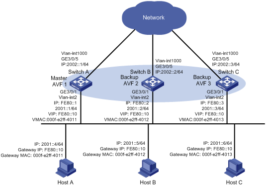
As shown in Figure 6, Switch A, Switch B, and Switch C form a load-balanced VRRP group and use the virtual IPv6 address FE80::10 to provide gateway service. Implement the following requirements:
· Switch A operates as the master of the VRRP group. When one of the switches in the VRRP group fails, the hosts can access the external network through other switches.
· Packets from the hosts are forwarded by different switches to reduce the burden of the master.
· When the upstream link of the AVF fails, the AVF can notify an LVF to take over.
Requirements analysis
For the AVF to notify an LVF to take over the AVF role when the upstream link of the AVF fails, configure VF tracking on each gateway to monitor the uplink.
Software version used
This configuration example was created and verified on S12500-CMW520-R1825P01.
Configuration restrictions and guidelines
When you configure IPv6 VRRP load balancing mode, follow these restrictions and guidelines:
· To make sure H3C S12500 switches can forward IPv6 packets correctly, enable IPv6 packet forwarding first. (This function is disabled by default.)
· To avoid affecting network performance, do not create VRRP groups in the VLAN interface on a super VLAN.
· In load balancing mode, the virtual IP address of a VRRP group cannot be the same as the IP address of any interface in the VRRP group.
Configuration procedures
Configuring Switch A
# Enable IPv6 packet forwarding.
<SwitchA> system-view
[SwitchA] ipv6
# Configure VLAN 2.
[SwitchA] vlan 2
[SwitchA-vlan2] port Gigabitethernet 3/0/1
[SwitchA-vlan2] quit
[SwitchA] interface GigabitEthernet 3/0/1
[SwitchA-GigabitEthernet3/0/1] undo shutdown
[SwitchA-GigabitEthernet3/0/1] quit
# Configure VRRP to operate in load balancing mode.
[SwitchA] vrrp mode load-balance
# Create VRRP group 1 and set its virtual IP address to FE80::10.
[SwitchA] interface vlan-interface 2
[SwitchA-Vlan-interface2] undo shutdown
[SwitchA-Vlan-interface2] ipv6 address fe80::1 link-local
[SwitchA-Vlan-interface2] ipv6 address 2001::1 64
[SwitchA-Vlan-interface2] vrrp ipv6 vrid 1 virtual-ip fe80::10 link-local
[SwitchA-Vlan-interface2] vrrp ipv6 vrid 1 virtual-ip 2001::10
# Set the priority of Switch A in VRRP group 1 to 120.
[SwitchA-Vlan-interface2] vrrp ipv6 vrid 1 priority 120
# Enable Switch A to send RA messages.
[SwitchA-Vlan-interface2] undo ipv6 nd ra halt
# Configure VRRP tracking for the VF and uplink interface tracking.
[SwitchA-Vlan-interface2] vrrp ipv6 vrid 1 weight track 1 reduced 255
[SwitchA-Vlan-interface2] quit
# Configure the uplink interface and the track entry.
[SwitchA] vlan 1000
[SwitchA-vlan1000] port Gigabitethernet 3/0/5
[SwitchA-vlan1000] quit
[SwitchA] interface GigabitEthernet 3/0/5
[SwitchA-GigabitEthernet3/0/5] undo shutdown
[SwitchA-GigabitEthernet3/0/5] quit
[SwitchA] interface vlan-interface 1000
[SwitchA-Vlan-interface1000] ipv6 address 2002::1/64
[SwitchA-Vlan-interface1000] undo shutdown
[SwitchA-Vlan-interface1000] quit
[SwitchA] track 1 interface Vlan-interface 1000 protocol ipv6
Configuring Switch B
# Enable IPv6 packet forwarding.
<SwitchB> system-view
[SwitchB] ipv6
# Configure VLAN 2.
[SwitchB] vlan 2
[SwitchB-vlan2] port Gigabitethernet 3/0/1
[SwitchB-vlan2] quit
[SwitchB] interface GigabitEthernet 3/0/1
[SwitchB-GigabitEthernet3/0/1] undo shutdown
[SwitchB-GigabitEthernet3/0/1] quit
# Configure VRRP to operate in load balancing mode.
[SwitchB] vrrp mode load-balance
# Create VRRP group 1 and set its virtual IP address to FE80::10.
[SwitchB] interface vlan-interface 2
[SwitchB-Vlan-interface2] undo shutdown
[SwitchB-Vlan-interface2] ipv6 address fe80::2 link-local
[SwitchB-Vlan-interface2] ipv6 address 2001::2 64
[SwitchB-Vlan-interface2] vrrp ipv6 vrid 1 virtual-ip fe80::10 link-local
[SwitchB-Vlan-interface2] vrrp ipv6 vrid 1 virtual-ip 2001::10
# Set the priority of Switch B in VRRP group 1 to 110.
[SwitchB-Vlan-interface2] vrrp ipv6 vrid 1 priority 110
# Enable Switch B to send RA messages.
[SwitchB-Vlan-interface2] undo ipv6 nd ra halt
# Configure VRRP tracking for the VF and uplink interface tracking.
[SwitchB-Vlan-interface2] vrrp ipv6 vrid 1 weight track 1 reduced 255
[SwitchB-Vlan-interface2] quit
# Configure the uplink interface and the track entry.
[SwitchB] vlan 1000
[SwitchB-vlan1000] port Gigabitethernet 3/0/5
[SwitchB-vlan1000] quit
[SwitchB] interface GigabitEthernet 3/0/5
[SwitchB-GigabitEthernet3/0/5] undo shutdown
[SwitchB-GigabitEthernet3/0/5] quit
[SwitchB] interface vlan-interface 1000
[SwitchB-Vlan-interface1000] ipv6 address 2002::2/64
[SwitchB-Vlan-interface1000] undo shutdown
[SwitchB-Vlan-interface1000] quit
[SwitchB] track 1 interface Vlan-interface 1000 protocol ipv6
Configuring Switch C
# Enable IPv6 packet forwarding.
<SwitchC> system-view
[SwitchC] ipv6
# Configure VLAN 2.
[SwitchC] vlan 2
[SwitchC-vlan2] port Gigabitethernet 3/0/5
[SwitchC-vlan2] quit
[SwitchC] interface GigabitEthernet 3/0/1
[SwitchC-GigabitEthernet3/0/1] undo shutdown
[SwitchC-GigabitEthernet3/0/1] quit
# Configure VRRP to operate in load balancing mode.
[SwitchC] vrrp mode load-balance
# Create VRRP group 1 and set its virtual IP address to FE80::10.
[SwitchC] interface vlan-interface 2
[SwitchC-Vlan-interface2] undo shutdown
[SwitchC-Vlan-interface2] ipv6 address fe80::3 link-local
[SwitchC-Vlan-interface2] ipv6 address 2001::3 64
[SwitchC-Vlan-interface2] vrrp ipv6 vrid 1 virtual-ip fe80::10 link-local
[SwitchC-Vlan-interface2] vrrp ipv6 vrid 1 virtual-ip 2001::10
# Enable Switch C to send RA messages.
[SwitchC-Vlan-interface2] undo ipv6 nd ra halt
# Configure VRRP tracking for the VF and uplink interface tracking.
[SwitchC-Vlan-interface2] vrrp ipv6 vrid 1 weight track 1 reduced 255
[SwitchC-Vlan-interface2] quit
# Configure the uplink interface and the track entry.
[SwitchC] vlan 1000
[SwitchC-vlan1000] port Gigabitethernet 3/0/5
[SwitchC-vlan1000] quit
[SwitchC] interface GigabitEthernet 3/0/5
[SwitchC-GigabitEthernet3/0/5] undo shutdown
[SwitchC-GigabitEthernet3/0/5] quit
[SwitchC] interface vlan-interface 1000
[SwitchC-Vlan-interface1000] ipv6 address 2002::3/64
[SwitchC-Vlan-interface1000] undo shutdown
[SwitchC-Vlan-interface1000] quit
[SwitchC] track 1 interface Vlan-interface 1000 protocol ipv6
Verifying the configuration
# Verify that the hosts can ping the external network. (Details not shown.)
# Display detailed information about VRRP group 1 on Switch A.
[SwitchA-Vlan-interface2] display vrrp ipv6 verbose
IPv6 Standby Information:
Run Mode : Load Balance
Run Method : Virtual MAC
Total number of virtual routers : 1
Interface Vlan-interface2
VRID : 1 Adver Timer : 100
Admin Status : Up State : Master
Config Pri : 120 Running Pri : 120
Preempt Mode : Yes Delay Time : 0
Auth Type : None
Virtual IP : FE80::10
2001::10
Member IP List : FE80::1 (Local, Master)
FE80::3 (Backup)
FE80::2 (Backup)
Forwarder Information: 3 Forwarders 1 Active
Config Weight : 255
Running Weight : 255
Forwarder 01
State : Active
Virtual MAC : 000f-e2ff-4011 (Owner)
Owner ID : 6697-1250-0100
Priority : 255
Active : local
Forwarder 02
State : Listening
Virtual MAC : 000f-e2ff-4012 (Learnt)
Owner ID : 00e0-6405-3100
Priority : 127
Active : FE80::2
Forwarder 03
State : Listening
Virtual MAC : 000f-e2ff-4013 (Learnt)
Owner ID : 00e0-3948-0100
Priority : 127
Active : FE80::3
Forwarder Weight Track Information:
Track Object : 1 State : Positive Weight Reduced : 255
# Display detailed information about VRRP group 1 on Switch B.
[SwitchB] display vrrp ipv6 verbose
IPv6 Standby Information:
Run Mode : Load Balance
Run Method : Virtual MAC
Total number of virtual routers : 1
Interface Vlan-interface2
VRID : 1 Adver Timer : 100
Admin Status : Up State : Backup
Config Pri : 110 Running Pri : 110
Preempt Mode : Yes Delay Time : 0
Auth Type : None
Virtual IP : FE80::10
2001::10
Member IP List : FE80::2 (Local, Backup)
FE80::3 (Backup)
FE80::1 (Master)
Forwarder Information: 3 Forwarders 1 Active
Config Weight : 255
Running Weight : 255
Forwarder 01
State : Listening
Virtual MAC : 000f-e2ff-4011 (Learnt)
Owner ID : 6697-1250-0100
Priority : 127
Active : FE80::1
Forwarder 02
State : Active
Virtual MAC : 000f-e2ff-4012 (Owner)
Owner ID : 00e0-6405-3100
Priority : 255
Active : local
Forwarder 03
State : Listening
Virtual MAC : 000f-e2ff-4013 (Learnt)
Owner ID : 00e0-3948-0100
Priority : 127
Active : FE80::3
Forwarder Weight Track Information:
Track Object : 1 State : Positive Weight Reduced : 255
# Display detailed information about VRRP group 1 on Switch C.
IPv6 Standby Information:
Run Mode : Load Balance
Run Method : Virtual MAC
Total number of virtual routers : 1
Interface Vlan-interface2
VRID : 1 Adver Timer : 100
Admin Status : Up State : Backup
Config Pri : 100 Running Pri : 100
Preempt Mode : Yes Delay Time : 0
Auth Type : None
Virtual IP : FE80::10
2001::10
Member IP List : FE80::3 (Local, Backup)
FE80::1 (Master)
FE80::2 (Backup)
Forwarder Information: 3 Forwarders 1 Active
Config Weight : 255
Running Weight : 255
Forwarder 01
State : Listening
Virtual MAC : 000f-e2ff-4011 (Learnt)
Owner ID : 6697-1250-0100
Priority : 127
Active : FE80::1
Forwarder 02
State : Listening
Virtual MAC : 000f-e2ff-4012 (Learnt)
Owner ID : 00e0-6405-3100
Priority : 127
Active : FE80::2
Forwarder 03
State : Active
Virtual MAC : 000f-e2ff-4013 (Owner)
Owner ID : 00e0-3948-0100
Priority : 255
Active : local
Forwarder Weight Track Information:
Track Object : 1 State : Positive Weight Reduced : 255
The output shows that in VRRP group 1, Switch A is the master and Switch B and Switch C are the backups. An active VF and two listening VFs exist on each switch.
# When Switch A fails, use the display vrrp ipv6 verbose command to display detailed information about the VRRP group on Switch C.
[SwitchC] display vrrp ipv6 verbose
IPv6 Standby Information:
Run Mode : Load Balance
Run Method : Virtual MAC
Total number of virtual routers : 1
Interface Vlan-interface2
VRID : 1 Adver Timer : 100
Admin Status : Up State : Backup
Config Pri : 100 Running Pri : 100
Preempt Mode : Yes Delay Time : 0
Auth Type : None
Virtual IP : FE80::10
2001::10
Member IP List : FE80::3 (Local, Backup)
FE80::2 (Master)
Forwarder Information: 3 Forwarders 2 Active
Config Weight : 255
Running Weight : 255
Forwarder 01
State : Active
Virtual MAC : 000f-e2ff-4011 (Take Over)
Owner ID : 6697-1250-0100
Priority : 85
Active : local
Redirect Time : 549 secs
Time-out Time : 1749 secs
Forwarder 02
State : Listening
Virtual MAC : 000f-e2ff-4012 (Learnt)
Owner ID : 00e0-6405-3100
Priority : 85
Active : FE80::2
Forwarder 03
State : Active
Virtual MAC : 000f-e2ff-4013 (Owner)
Owner ID : 00e0-3948-0100
Priority : 255
Active : local
Forwarder Weight Track Information:
Track Object : 1 State : Positive Weight Reduced : 255
The output shows that Switch B becomes the master after Switch A fails. Switch C becomes an active VF with virtual MAC address 000F-E2FF-4011 mapped to it and forwards packets sent by Host A.
Configuration files
· Switch A:
#
ipv6
#
vrrp mode load-balance
#
vlan 2
#
vlan 1000
#
interface Vlan-interface2
ipv6 address 2001::1/64
ipv6 address FE80::1 link-local
vrrp ipv6 vrid 1 virtual-ip FE80::10 link-local
vrrp ipv6 vrid 1 virtual-ip 2001::10
vrrp ipv6 vrid 1 priority 120
vrrp ipv6 vrid 1 weight track 1 reduced 255
undo ipv6 nd ra halt
#
interface Vlan-interface1000
ipv6 address 2002::1/64
#
interface GigabitEthernet3/0/1
port link-mode bridge
port access vlan 2
#
interface GigabitEthernet3/0/5
port link-mode bridge
port access vlan 1000
#
track 1 interface Vlan-interface1000 protocol ipv6
#
· Switch B:
#
ipv6
#
vrrp mode load-balance
#
vlan 2
#
vlan 1000
#
interface Vlan-interface2
ipv6 address 2001::2/64
ipv6 address FE80::2 link-local
vrrp ipv6 vrid 1 virtual-ip FE80::10 link-local
vrrp ipv6 vrid 1 virtual-ip 2001::10
vrrp ipv6 vrid 1 priority 110
vrrp ipv6 vrid 1 weight track 1 reduced 255
undo ipv6 nd ra halt
#
interface Vlan-interface1000
ipv6 address 2002::2/64
#
interface GigabitEthernet3/0/1
port link-mode bridge
port access vlan 2
#
interface GigabitEthernet3/0/5
port link-mode bridge
port access vlan 1000
#
track 1 interface Vlan-interface1000 protocol ipv6
#
· Switch C:
#
ipv6
#
vrrp mode load-balance
#
vlan 2
#
vlan 1000
#
interface Vlan-interface2
ipv6 address 2001::3/64
ipv6 address FE80::3 link-local
vrrp ipv6 vrid 1 virtual-ip FE80::10 link-local
vrrp ipv6 vrid 1 virtual-ip 2001::10
vrrp ipv6 vrid 1 weight track 1 reduced 255
undo ipv6 nd ra halt
#
interface Vlan-interface1000
ipv6 address 2002::3/64
#
interface GigabitEthernet3/0/1
port link-mode bridge
port access vlan 2
#
interface GigabitEthernet3/0/5
port link-mode bridge
port access vlan 1000
#
track 1 interface Vlan-interface1000 protocol ipv6
#
Related documentation
· H3C S12500 Routing Switch Series High Availability Configuration Guide
· H3C S12500 Routing Switch Series High Availability Command Reference
· H3C S12500 Routing Switch Series Layer 2—LAN Switching Configuration Guide
· H3C S12500 Routing Switch Series Layer 2—LAN Switching Command Reference