- Table of Contents
-
- 13-Network Management and Monitoring Configuration Guide
- 00-Preface
- 01-System Maintenance and Debugging Configuration
- 02-NQA Configuration
- 03-NTP Configuration
- 04-Clock Monitoring Configuration
- 05-IPC Configuration
- 06-SNMP Configuration
- 07-RMON Configuration
- 08-CWMP Configuration
- 09-Sampler Configuration
- 10-Mirroring Configuration
- 11-Protocol Packet Statistics Configuration
- 12-sFlow Configuration
- 13-Information Center Configuration
- Related Documents
-
| Title | Size | Download |
|---|---|---|
| 08-CWMP Configuration | 613.15 KB |
Configuring ACS parameters through DHCP
Configuring the ACS username and password
Configuring the CPE username and password
Configuring the CWMP connection interface
Configuring the maximum number of attempts made to retry a connection
Configuring the close-wait timer of the CPE
Configuring the CPE working mode
Specifying an SSL client policy for HTTPS connection to ACS
Displaying and maintaining CWMP
Overview
The CPE WAN Management Protocol (CWMP), also called “TR-069,” is a DSL Forum technical specification for remote management of home network devices. It defines the general framework, message format, management method, and data model for managing and configuring home network devices.
CWMP is mainly applied to DSL access networks, which are hard to manage because end-user devices are dispersed and large in number. CWMP makes the management easier by using an auto-configuration server (ACS) to perform remote centralized management of customer premises equipment (CPE).
CWMP network framework
Figure 1 shows a basic CWMP network framework.
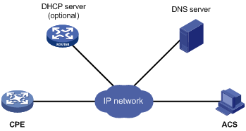
The basic CWMP network elements include:
· ACS—Auto-configuration server, the management device in the network.
· CPE—Customer premises equipment, the managed device in the network.
· DNS server—Domain name system server. CWMP defines that an ACS and a CPE use URLs to identify and access each other. DNS is used to resolve the URLs.
· DHCP server—Dynamic Host Configuration Protocol server, which assigns IP addresses to CPEs, and uses the options filed in the DHCP packet to provide configuration parameters to the CPE.
The switch can work as the CPE but not the ACS.
You can use the management Ethernet interface, a VLAN interface, a Layer 3 Ethernet interface or a Layer 3 Ethernet subinterface as the CWMP connection interface for communication between the switch and the ACS.
Basic CWMP functions
Auto-connection between ACS and CPE
A CPE can connect to an ACS automatically by sending an Inform message. The following conditions may trigger an auto-connection establishment:
· A CPE is started up. A CPE can find the corresponding ACS according to the acquired URL, and automatically initiates a connection to the ACS.
· A CPE is configured to send Inform messages periodically. The CPE will automatically send an Inform message at the configured interval (One hour for example) to establish connections.
· A CPE is configured to send an Inform message at a specific time. The CPE will automatically send an Inform message at the configured time to establish a connection.
An ACS can initiate a connection request to a CPE at any time, and can establish a connection with the CPE after passing CPE authentication.
Auto-configuration
When a CPE logs in to an ACS, the ACS can automatically apply some configurations to the CPE for it to perform auto configuration. Auto-configuration parameters supported by the ACS include (but are not limited to) the following:
· Configuration file (ConfigFile)
· ACS address (URL)
· ACS username (Username)
· ACS password (Password)
· PeriodicInformEnable
· PeriodicInformInterval
· PeriodicInformTime
· CPE username (ConnectionRequestUsername)
· CPE password (ConnectionRequestPassword)
CPE system software image file and configuration file management
The network administrator can save CPE system software image files and configuration files on the ACS and configure the ACS to automatically ask the CPE to download any update made to these files. After the CPE receives an update request, it automatically downloads the updated file from the file server according to the filename and server address in the ACS request. After downloading the file, the CPE checks the file validity and reports the download result (success or failure) to the ACS.
|
|
NOTE: · The device can download only system software images (in .bin format) and configuration files from the ACS, and does not support digital signatures. · When the device downloads a system software image file, it updates the old main software image file with the content of the new file but keeps the old file name unchanged. · If the root directory for the main system software image file is set as CF:/, but no main system software image file is found on the CF card, the device downloads the new system software image file to Flash. To use the file, you must re-specify the new file as the main system software image file for the device to boot from Flash. |
To backup important data, a CPE can upload the current configuration file to the specified server according to the requirement of an ACS. Currently, the device only supports uploading the vendor configuration file or log file.
CPE status and performance monitoring
An ACS can monitor the parameters of a CPE connected to it. Different CPEs have different performances and functionalities. Therefore the ACS must be able to identify each type of CPE and monitor the current configuration and configuration changes of each CPE. CWMP also allows the administrator to define monitor parameters and get the parameter values through an ACS, so as to get the CPE status and statistics information.
The status and performance that can be monitored by an ACS include:
· Manufacture name (Manufacturer)
· ManufacturerOUI
· SerialNumber
· HardwareVersion
· SoftwareVersion
· DeviceStatus
· UpTime
· Configuration file (ConfigFile)
· ACS address (URL)
· ACS username (Username)
· ACS password (Password)
· PeriodicInformEnable
· PeriodicInformInterval
· PeriodicInformTime
· CPE address (ConnectionRequestURL)
· CPE username (ConnectionRequestUsername)
· CPE password (ConnectionRequestPassword)
CWMP mechanism
RPC methods
CWMP provides the following major remote procedure call (RPC) methods for an ACS to manage or monitor a CPE:
· Get—The ACS gets the value of one or more parameters from the CPE.
· Set—The ACS sets the value of one or more parameters on the CPE.
· Inform—The CPE sends an Inform message to an ACS whenever the CPE initiates a connection to the ACS, or the CPE’s underlying configuration changes, or the CPE periodically sends its local information to the ACS.
· Download—The ACS requires a CPE to download a specific file from the specified URL, ensuring upgrading of CPE software and auto download of the vendor configuration file.
· Upload—The ACS requires a CPE to upload a specific file to the specified location.
· Reboot—The ACS remotely reboots the CPE when the CPE encounters a failure or completes a software upgrade.
How CWMP works
The following example illustrates how CWMP works. The scenario: There are two ACSs, main and backup in an area. The main ACS needs to restart for system upgrade. To ensure a continuous monitoring of the CPE, the main ACS needs to let all CPEs in the area connect to the backup ACS.
Figure 2 Example of the CWMP message interaction
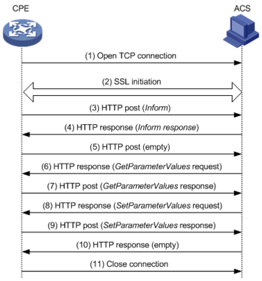
The whole process is as follows:
1. Establish a TCP connection.
2. SSL initialization, and establish a security connection.
3. The CPE sends an Inform request message to initiate a CWMP connection. The Inform message carries the reason for sending this message in the Eventcode field. In this example, the reason is “6 CONNECTION REQUEST”, indicating that the ACS requires the CPE to establish a connection.
4. If the CPE passes the authentication of the ACS, the ACS returns an Inform response, and the connection is established.
5. Receiving the Inform response, the CPE sends an empty message, if it has no other requests. The CPE does this in order to comply with the request/reply interaction model of HTTP/HTTPS, in which CWMP messages are conveyed.
6. The ACS queries the value of the ACS URL set on the CPE.
7. The CPE replies to the ACS with the obtained value of the ACS URL.
8. The ACS finds that its local URL value is the same as the value of the ACS URL on the CPE. Therefore, the ACS sends a Set request to the CPE to modify the ACS URL value of the CPE to the URL of the backup ACS.
9. The setting succeeds and the CPE sends a response.
10. The ACS sends an empty message to notify the CPE that it has no other requests.
11. The CPE closes the connection.
After this, the CPE will initiate a connection to the backup ACS.
CWMP configuration approaches
The CWMP parameters can be configured in three modes: ACS, DHCP, and command line interface (CLI). Support for these configuration modes varies with the parameters. For details, see Table 1.
Configuring CWMP through ACS
An ACS performs auto-configuration of a CPE through remote management. For the primary configurable parameters, see “Auto-configuration.”
Configuring ACS parameters through DHCP
You can configure ACS parameters for the CPE on the DHCP server by using DHCP Option 43. When accessed by the CPE, the DHCP server sends the ACS parameters in DHCP Option 43 to the CPE. If the DHCP server is an H3C device that supports DHCP Option 43, you can configure the ACS parameters at the CLI with the command option 43 hex 01length URL username password, where:
· length is a hexadecimal string that indicates the total length of the URL username password arguments. No space is allowed between the 01 keyword and the length value.
· URL is the ACS address.
· username is the ACS username.
· password is the ACS password.
When you configure the ACS URL, username and password, follow these guidelines:
· The three arguments take the hexadecimal format and the ACS URL and username must each end with a space (20 in hexadecimal format) for separation.
· The three arguments must be input in 2-digit, 4-digit, 6-digit, or 8-digit segments, each separated by a space.
For example, to set the ACS address to http://169.254.76.31:7547/acs, username to 1234, and password to 5678, you can configure as follows:
<Sysname> system-view
[Sysname] dhcp server ip-pool 0
[Sysname-dhcp-pool-0] option 43 hex 0127 68747470 3A2F2F31 36392E32 35342E37 362E3331 3A373534 372F6163 73203132 33342035 3637 38
In the option 43 hex command:
· 27 indicates that the length of the subsequent hexadecimal strings is 39 characters.
· 68747470 3A2F2F31 36392E32 35342E37 362E3331 3A373534 372F6163 73 corresponds to the ACS address http://169.254.76.31/acs.
· 3132 3334 corresponds to the username 1234.
· 35 3637 38 corresponds to the password 5678.
· 20 is the end delimiter.
|
|
NOTE: For more information about DHCP, DHCP Option 43, and the option command, see Layer 3—IP Services Configuration Guide. |
Configuring CWMP at the CLI
You can set CWMP parameters on your device (the CPE) at the CLI.
Complete these tasks to configure CWMP:
Table 1 CWMP configuration task list
|
Task |
Remarks |
|
|
Required. |
||
|
Required. Supports configuration through ACS, DHCP, and CLI. |
||
|
Optional. Supports configuration through ACS, DHCP, and CLI. |
||
|
Optional. Supports configuration through ACS and CLI. |
||
|
Optional. Supports configuration through CLI only. |
||
|
Optional. Supports configuration through ACS and CLI. |
||
|
Configuring the maximum number of attempts made to retry a connection |
Optional. Supports configuration through CLI only. |
|
|
Optional. Supports configuration through CLI only. |
||
|
Optional. Supports configuration through CLI only. |
||
|
Optional. Supports configuration through CLI only. |
||
Enabling CWMP
CWMP configurations can take effect only after you enable CWMP.
To enable CWMP:
|
Step |
Command |
Remarks |
|
1. Enter system view. |
system-view |
N/A |
|
2. Enter CWMP view. |
cwmp |
N/A |
|
3. Enable CWMP. |
cwmp enable |
Optional. By default, CWMP is enabled. |
Configuring ACS attributes
Configuring the ACS URL
You can assign only one ACS for a CPE and the ACS URL you configured overwrites the old one, if any.
To configure the ACS URL:
|
Step |
Command |
Remarks |
|
system-view |
N/A |
|
|
2. Enter CWMP view. |
cwmp |
N/A |
|
3. Configure the ACS URL. |
cwmp acs url url |
By default, no ACS URL is configured. |
Configuring the ACS username and password
To pass ACS authentication, make sure that the configured username and password are the same as those configured for the CPE on the ACS.
To configure the ACS username and password:
|
Step |
Command |
Remarks |
|
1. Enter system view. |
system-view |
N/A |
|
2. Enter CWMP view. |
cwmp |
N/A |
|
3. Configure the ACS username for connection to the ACS. |
cwmp acs username username |
By default, no ACS username is configured for connection to the ACS. |
|
4. Configure the ACS password for connection to the ACS. |
cwmp acs password password |
Optional. You can specify a username without a password for authentication, but must make sure that the ACS has the same authentication setting as the CPE. By default, no ACS password is configured for connection to the ACS. |
Configuring CPE attributes
Configuring the CPE username and password
To configure the CPE username and password:
|
Step |
Command |
Remarks |
|
1. Enter system view. |
system-view |
N/A |
|
2. Enter CWMP view. |
cwmp |
N/A |
|
3. Configure the CPE username for connection to the CPE. |
cwmp cpe username username |
By default, no CPE username is configured for connection to the CPE. |
|
4. Configure the CPE password for connection to the CPE. |
cwmp cpe password password |
Optional. You can specify a username without a password for authentication, but must make sure that the ACS has the same authentication setting as the CPE. By default, no CPE password is configured for connection to the CPE. |
Configuring the CWMP connection interface
The CWMP connection interface is the interface that the CPE uses to communicate with the ACS. The CPE sends the IP address of this interface in the Inform messages and the ACS replies to this IP address for setting up a CWMP connection.
If the interface that connects the CPE to the ACS is the only Layer 3 interface that has an IP address on the switch, you do not need to specify the CWMP connection interface. If multiple Layer 3 interfaces are configured, specify the CWMP connection interface to make sure that the IP address of the interface connects to the ACS is sent to the ACS for setting up CWMP connection.
To configure a CWMP connection interface:
|
Step |
Command |
|
1. Enter system view. |
system-view |
|
2. Enter CWMP view. |
cwmp |
|
3. Set the interface that connects the CPE to the ACS. |
cwmp cpe connect interface interface-type interface-number |
Sending Inform messages
Inform messages need to be sent during the connection establishment between a CPE and an ACS. You can configure the Inform message sending parameter to trigger the CPE to initiate a connection to the ACS.
Sending an Inform message periodically
To configure the CPE to periodically send Inform messages:
|
Step |
Command |
Remarks |
|
1. Enter system view. |
system-view |
N/A |
|
2. Enter CWMP view. |
cwmp |
N/A |
|
3. Enable the periodical sending of Inform messages. |
cwmp cpe inform interval enable |
By default, the function is disabled. |
|
4. Configure the interval between sending the Inform messages. |
cwmp cpe inform interval seconds |
Optional. By default, the CPE sends an Inform message every 600 seconds. |
Sending an Inform message at a specific time
To configure the CPE to send an Inform message at a specific time:
|
Step |
Command |
Remarks |
|
1. Enter system view. |
system-view |
N/A |
|
2. Enter CWMP view. |
cwmp |
N/A |
|
3. Configure the CPE to send an Inform message at a specific time. |
cwmp cpe inform time time |
By default, no time is set. The CPE is not configured to send an Inform message at a specific time. |
Configuring the maximum number of attempts made to retry a connection
If a CPE fails to establish a connection to an ACS, or the connection is interrupted during the session (the CPE does not receive a message indicating the normal close of the session), the CPE can automatically reinitiate a connection to the ACS.
To configure the maximum number of attempts that a CPE can make to retry a connection:
|
Step |
Command |
Remarks |
|
1. Enter system view. |
system-view |
N/A |
|
2. Enter CWMP view. |
cwmp |
N/A |
|
3. Configure the maximum number of attempts that a CPE can make to retry a connection. |
cwmp cpe connect retry times |
Optional. Infinity by default, that is, a CPE sends connection requests to the ACS at a specified interval all along. |
Configuring the close-wait timer of the CPE
The close-wait timer is used mainly in the following cases:
· During the establishment of a connection, if the CPE sends connection requests to the ACS, but the CPE does not receive a response within the configured close-wait timeout, the CPE will consider the connection failed.
· After a connection is established, if there is no packet interaction between the CPE and ACS within the configured close-wait timeout, the CPE will consider the connection invalid, and disconnect the connection.
To configure the close-wait timer for the CPE:
|
Step |
Command |
Remarks |
|
1. Enter system view. |
system-view |
N/A |
|
2. Enter CWMP view. |
cwmp |
N/A |
|
3. Set the CPE close-wait timer. |
cwmp cpe wait timeout seconds |
Optional. 30 seconds by default. |
Configuring the CPE working mode
Configure the device to work in one of the following CPE modes depending on its position in the network:
· Gateway mode—Enables the ACS to manage the device and any CPE attached to the device. Use this mode if the device is the egress to the WAN and has lower-level CPEs.
· Device mode—If no CPEs are attached to the device, configure the device to work in device mode.
Disable CWMP before you change the CPE working mode.
To configure the working mode of the CPE:
|
Step |
Command |
Remarks |
|
1. Enter system view. |
system-view |
N/A |
|
2. Enter CWMP view. |
cwmp |
N/A |
|
3. Configure the working mode of the CPE. |
cwmp device-type { device | gateway } |
Optional. By default, the device works in gateway mode. |
Specifying an SSL client policy for HTTPS connection to ACS
CWMP uses HTTP or HTTPS for data transmission. If the ACS uses HTTPS for secure access, its URL begins with https://. You must configure an SSL client policy for the CPE to authenticate the ACS for establishing an HTTPS connection. For more information about configuring SSL client policies, see Security Configuration Guide.
To specify an SSL client policy for the CPE to establish an HTTPS connection to the ACS:
|
Step |
Command |
Remarks |
|
1. Enter system view. |
system-view |
N/A |
|
2. Enter CWMP view. |
cwmp |
N/A |
|
3. Specify an SSL client policy. |
ssl client-policy policy-name |
By default, no SSL client policy is configured. |
Displaying and maintaining CWMP
|
Task |
Command |
Remarks |
|
Display CWMP configuration. |
display cwmp configuration [ | { begin | exclude | include } regular-expression ] |
Available in any view |
|
Display the current status of CWMP. |
display cwmp status [ | { begin | exclude | include } regular-expression ] |
Available in any view |
CWMP configuration example
|
|
NOTE: This example uses H3C iMC installed with the BIMS component to provide ACS service. The BIMS web interface might change along with software updates. |
Network requirements
A data center has two equipment rooms A and B. Both rooms require a great number of switches. There are ACS, DHCP, and DNS servers on the network. To improve deployment efficiency, use CWMP to deliver different configuration files to the switches in rooms A and B.
Figure 3 Network diagram
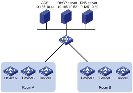
Table 2 Switches deployed in two equipment rooms
|
Equipment room |
Switch |
Serial ID |
|
A |
Device A |
210231A95YH10C0000045 |
|
Device B |
210235AOLNH12000010 |
|
|
Device C |
210235AOLNH12000015 |
|
|
B |
Device D |
210235AOLNH12000017 |
|
Device E |
210235AOLNH12000020 |
|
|
Device F |
210235AOLNH12000022 |
The network administrator has created two configuration files sys.a.cfg and sys_b.cfg for the switches in room A and room B. The username and password for accessing the ACS server is admin and 12345. The URL address of the ACS is http://10.185.10.41:8080/acs.
Configuration procedure
Configuring the ACS (IMC)
1. Log in to the ACS (iMC):
a. Launch a web browser, and enter the IP address and port number of IMC, for example, http://10.185.10.41:8080/imc, in the address bar of the browser.
b. Enter the username and password (admin by default) to log in to iMC.
2. Set a CPE username and password:
a. Select Service > BIMS > CPE Authentication Users from the navigation bar.
b. Click Add on the CPE authentication user page.
Figure 4 CPE authentication user page
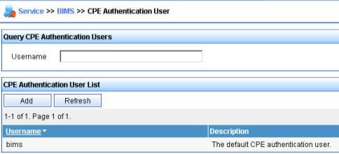
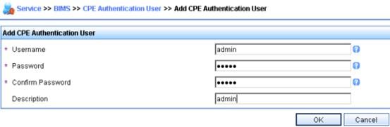
c. Set the CPE username, password, and description, and click OK.
Figure 5 Adding CPE authentication user page
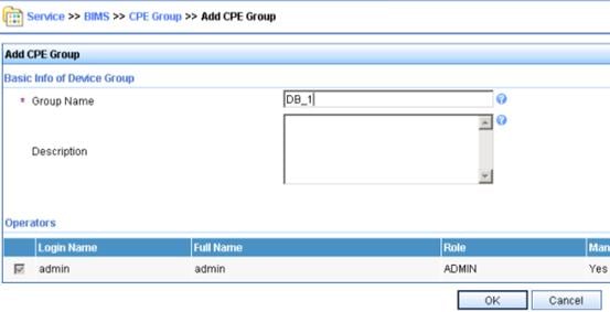
3. Add device groups and device classes for the switches in room A and room B. This procedure uses configuring the switches in room A as an example.
a. Select Service > BIMS > CPE Group from the navigation bar.
b. Click Add on the page that appears.
c. Set the group name (DB_1 in this example) and click OK.
Figure 6 Adding device group page
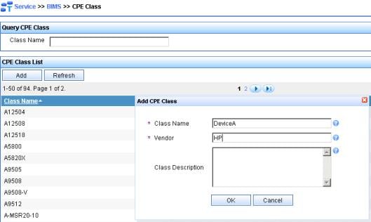
d. Select Service > BIMS > CPE Class from the navigation bar.
e. Click Add on the page that appears.
f. Set the CPE class on the page in Figure 7 and click OK.
Figure 7 Adding device class page
g. Select Service > BIMS > Add CPE from the navigation bar.
h. Configure information about one CPE in room A on the page in Figure 8 and click OK.
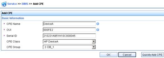
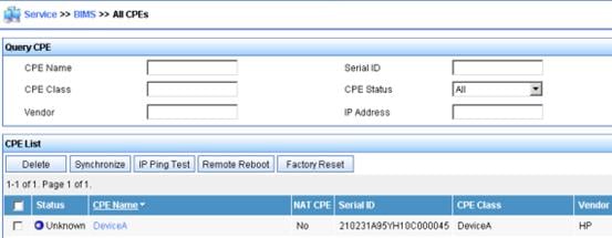
If the CPE is successfully added, the page in Figure 9 appears.
Figure 9 Adding device succeeded
i. Repeat the previous two steps to add all the switches in equipment room A to the ACS.
4. Set ACS parameters:
a. Select Service > BIMS > System Settings from the navigation bar.
b. Set each ACS parameter, including the ACS username and password in the CPE Access Parameters area, and click OK.
Figure 10 Setting system parameters

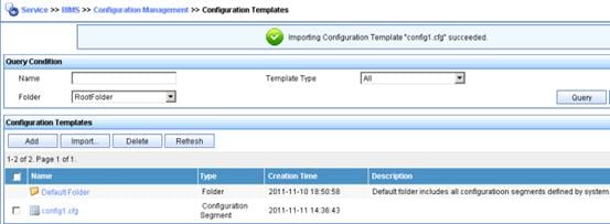
5. Configure the configuration file template and system software image deployment template for the CPEs:
a. Select Service > BIMS > Configuration Management > Configuration Templates from the navigation bar.
Figure 11 Configuring the configuration templates
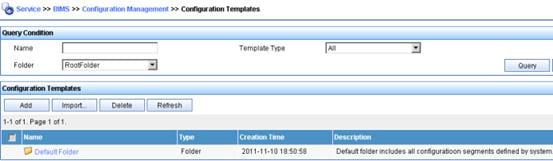
b. Click Import to enter the page for importing configuration templates.
c. Set the configuration template, including the source and destination files, as shown in Figure 12.
Figure 13 shows that the configuration template is successfully added.
Figure 12 Importing configuration templates
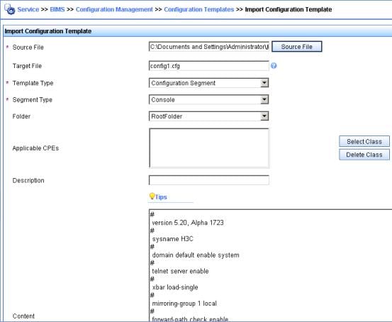
Figure 13 Configuration templates task succeeded
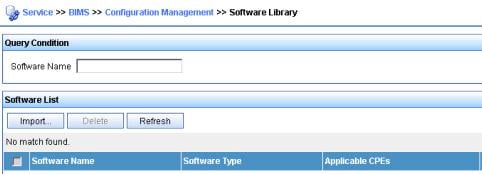
d. Select Service > BIMS > Configuration Management > Software Library from the navigation bar to enter the page for configuring CPE software.
e. Click Import on the page (Figure 14) that appears.
Figure 14 Configuring CPE software
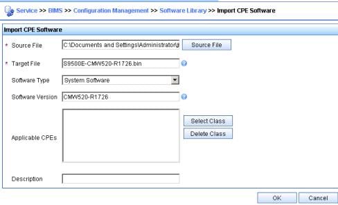
f. Set the software template as shown in Figure 15, and click OK.
Figure 15 Importing CPE software
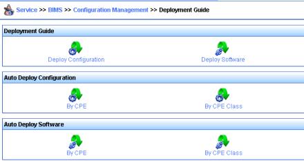
6. Configure auto-deployment of configuration files and system software images.
a. Select Service > BIMS > Configuration Management > Deployment Guide from the navigation bar.
b. In the Auto Deploy Configuration area, click By CPE Class.
Figure 16 Deployment guide page
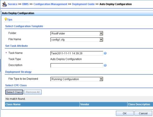
c. On the page in Figure 17, select the configuration template, set task attributes, select Running Configuration from the File Type to be Deployed list in the Deployment Strategy area, and click Select Class.
Figure 17 Auto deploy configuration page
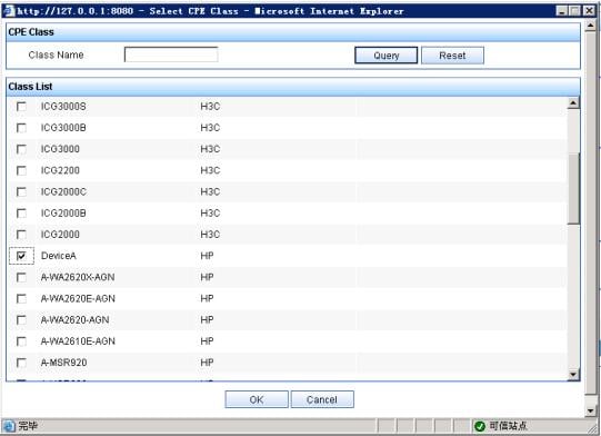
d. On the page (Figure 18) that appears, select the Device_A CPE class and click OK.
Figure 18 Selecting CPE class page
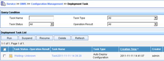
e. On the auto deploy configuration page, click OK to complete the task.
Figure 19 Deploying task succeeded
Configuring the DHCP server
|
|
NOTE: In this example, the DHCP server is an H3C switch that supports DHCP Option 43. If your DHCP server is not an H3C switch supporting the Option 43 function, see the user manual came with your server. |
1. Configure a DHCP address pool. Assign IP addresses to CPEs and the DNS server. In this example, the addresses are in the network segment 10.185.10.0/24.
# Enable DHCP.
<DHCP_server> system-view
[DHCP_server] dhcp enable
# Enable the DHCP server on VLAN-interface 1.
[DHCP_server] interface vlan-interface 1
[DHCP_server-Vlan-interface1] dhcp select server global-pool
[DHCP_server-Vlan-interface1] quit
# Exclude IP addresses (addresses of the DNS server and ACS server).
[DHCP_server] dhcp server forbidden-ip 10.185.10.41
[DHCP_server] dhcp server forbidden-ip 10.185.10.60
# Configure DHCP address pool 0 (subnet and DNS server address).
[DHCP_server] dhcp server ip-pool 0
[DHCP_server-dhcp-pool-0] network 10.185.10.0 mask 255.255.255.0
[DHCP_server-dhcp-pool-0] dns-list 10.185.10.60
2. Configure Option 43 to contain the ACS address, username, and password.
# Covert the ACS address, username, and password to ASCII code. The ASCII code of the URL address is 68 74 74 70 3A 2F 2F 61 63 73 2E 64 61 74 61 62 61 73 65 3A 39 30 39 30 2F 61 63 73, that of the username admin is 76 69 63 6B 79, and that of the password 12345 is 31 32 33 34 35.
[DHCP_server-dhcp-pool-0] option 43 hex 0140 68747470 3A2F2F61 63732E64 61746162 6173653A 39303930 2F616373 20766963 6B792031 32333435
Configuring the DNS server
Configure the mappings between the domain name and IP address, that is, create the mapping between the addresses http://acs.database:9090/acs and http://10.185.1.41:9090/acs. For how to create a mapping between addresses, see the user manual came with your DNS server.
Connecting the CPEs to the network
Connect the CPEs with network cables and power them on, the CPEs can obtain the IP address and other information for accessing the ACS through DHCP, and then automatically obtain configuration files from the ACS server.
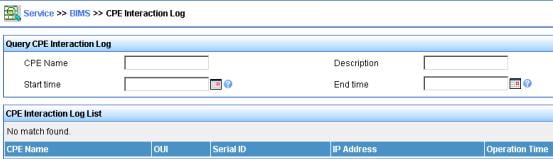
Verifying the configuration on the ACS server
Select Service > BIMS > CPE Interaction Log from the navigation tree to enter the page for querying device interaction records. You can view whether the deployment configuration of a switch is completed.
Figure 20 Device interaction log page