- Table of Contents
-
- 13-Network Management and Monitoring Configuration Guide
- 00-Preface
- 01-System Maintenance and Debugging Configuration
- 02-NQA Configuration
- 03-NTP Configuration
- 04-Clock Monitoring Configuration
- 05-IPC Configuration
- 06-SNMP Configuration
- 07-RMON Configuration
- 08-CWMP Configuration
- 09-Sampler Configuration
- 10-Mirroring Configuration
- 11-Protocol Packet Statistics Configuration
- 12-sFlow Configuration
- 13-Information Center Configuration
- Related Documents
-
| Title | Size | Download |
|---|---|---|
| 10-Mirroring Configuration | 341.61 KB |
Contents
Terminologies of port mirroring
Port mirroring classification and implementation
Configuring local port mirroring
Local port mirroring configuration task list
Creating a local mirroring group
Configuring source ports for the local mirroring group
Configuring source VLANs for the local mirroring group
Configuring the monitor port for the local mirroring group
Configuring Layer 2 remote port mirroring
Layer 2 remote port mirroring configuration task list with configurable reflector port available
Configuring a remote source group on the source device
Configuring a remote destination group on the destination device
Displaying and maintaining port mirroring
Port mirroring configuration examples
Local port mirroring configuration example (in source port mode)
Local port mirroring configuration example (in source VLAN mode)
Layer 2 remote port mirroring configuration example (reflector port configurable)
Traffic mirroring configuration task list
Configuring traffic mirroring of different types
Displaying and maintaining traffic mirroring
Traffic mirroring configuration example
|
|
NOTE: The switch operates in IRF or standalone (default) mode. For more information about the IRF mode, see IRF Configuration Guide. |
Introduction
Port mirroring refers to the process of copying the packets that pass through a port/VLAN (called a mirroring port/VLAN) to another port (called the monitor port) connected with a monitoring device for packet analysis.
You can select to port-mirror inbound, outbound, or bidirectional traffic on a port/VLAN as needed. The switch does not support sampling the mirrored outbound traffic of ports. For more information about packet sampling, see the chapter “Configuring samplers.”
|
|
NOTE: The number of monitor ports supported in each direction is: · One monitor port on a 24-port GE interface board; · Two monitor ports on a 48-port GE interface board (except LSR2GV48REB1), one for the first 24 ports, and the other for the remaining 24 ports; · One monitor port on an LSR2GV48REB1 interface board; · One monitor port for every two 10-GE ports (arranged by port number) on a 10-GE interface board (except LSR1XP16REB1); · Two monitor ports on an LSR1XP16REB1 interface board, one for the first eight 10-GE ports (arranged by port number), and one for the remaining eight 10-GE ports (arranged by port number). |
Terminologies of port mirroring
Mirroring source
The mirroring source can be one or more monitored ports, all ports in one or more VLANs. Packets (called mirrored packets) passing through them are copied to a port connecting to a monitoring device for packet analysis. Such a port/VLAN is called a source port/VLAN and the device where the port or CPU resides is called a source device.
Mirroring destination
The mirroring destination is the destination port (also known as the monitor port) of mirrored packets and connects to the data monitoring device. The device where the monitor port resides is called the destination device. The monitor port forwards mirrored packets to its connecting monitoring device.
|
|
NOTE: · A monitor port may receive multiple duplicates of a packet in some cases because it can monitor multiple mirroring sources. For example, assume that Port 1 is monitoring bidirectional traffic on Port 2 and Port 3 on the same device. If a packet travels from Port 2 to Port 3, two duplicates of the packet will be received on Port 1. · The switch in IRF mode does not support mirroring packets from specified source VLANs to the monitor port. · The switch does not port mirroring where the monitor port and source ports (or ports in the source VLANs) reside on different devices in IRF mode. |
Mirroring direction
The mirroring direction indicates that the inbound, outbound, or bidirectional traffic can be copied on a mirroring source:
· Inbound—Copies packets received on a mirroring source.
· Outbound—Copies packets sent out a mirroring source.
· Bidirectional—Copies packets both received and sent on a mirroring source.
Mirroring group
Port mirroring is implemented through mirroring groups, which fall into local, remote source, and remote destination mirroring groups. For more information about the mirroring groups, see “Port mirroring classification and implementation.”
Reflector port, egress port, and remote probe VLAN
A reflector port, remote probe VLAN, and an egress port are used for Layer 2 remote port mirroring. The remote probe VLAN specially transmits mirrored packets to the destination device. Both the reflector port and egress port reside on a source device and send mirrored packets to the remote probe VLAN. The egress port must belong to the remote probe VLAN while the reflector port may not. For more information about the source device, destination device, reflector port, egress port, and remote probe VLAN, see “Port mirroring classification and implementation.“
Port mirroring classification and implementation
According to the locations of the mirroring source and the mirroring destination, port mirroring falls into local port mirroring and remote port mirroring.
Local port mirroring
In local port mirroring, the mirroring source and the mirroring destination are on the same device. A mirroring group that contains the mirroring source and the mirroring destination on the device is called a local mirroring group.
Figure 1 Local port mirroring implementation
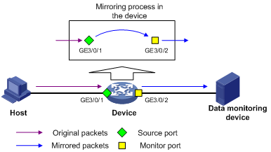
As shown in Figure 1, the source port GigabitEthernet 3/0/1 and monitor port GigabitEthernet 3/0/2 reside on the same device. Packets of GigabitEthernet 3/0/1 are copied to GigabitEthernet 3/0/2, which then forwards the packets to the data monitoring device for analysis.
Remote port mirroring
In remote port mirroring, the mirroring source and the mirroring destination reside on different devices and in different mirroring groups. The mirroring group that contains the mirroring source or the mirroring destination is called a remote source/destination group. The devices between the source devices and destination device are intermediate devices.
Remote port mirroring falls into Layer 2 and Layer 3 remote port mirroring:
· In Layer 2 remote port mirroring, the mirroring source and the mirroring destination are located on different devices on a same Layer 2 network.
· In Layer 3 remote port mirroring, the mirroring source and the mirroring destination are separated by IP networks. The switch does not support Layer 3 remote port mirroring.
The follow section describes Layer 2 remote port mirroring.
|
|
NOTE: Layer 2 remote port mirroring can be implemented when a fixed reflector port, configurable reflector port, or configurable egress port is available on the source device. The configuration method when either of the first two ports is available on the source device is called reflector port method. You must configure a reflector port on the source device that has a configurable reflector port. The switch only supports Layer 2 remote port mirroring with a configurable reflector port. |
Figure 2 Layer 2 remote port mirroring implementation (with a reflector port)
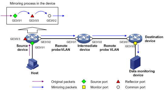
On the network shown in Figure 2, the source device copies the packets received on the source port GigabitEthernet 3/0/1 to the reflector port GigabitEthernet 3/0/3. GigabitEthernet 3/0/3 broadcasts the packets in the remote probe VLAN and the intermediate device in the VLAN transmits the packets to the destination device. When receiving these mirrored packets, the destination device compares their VLAN IDs to the ID of the remote probe VLAN configured in the remote destination group. If the VLAN IDs of these mirrored packets match the remote probe VLAN ID, the device forwards them to the data monitoring device through the monitor port.
|
|
NOTE: · Allow remote probe VLAN to pass through the intermediate devices to make sure that the source device and the destination device can communicate at Layer 2 in the remote probe VLAN. · For a mirrored packet to successfully arrive at the remote destination device, make sure the VLAN ID of the mirrored packet is not removed or changed. Otherwise, the Layer 2 remote port mirroring configuration will fail. · For the reflector port method, you can implement the local port mirroring function by assigning the other ports on the source device to the remote probe VLAN, because the source device broadcasts mirrored packets in the remote probe VLAN. · To monitor both the received and sent packets of a port in a mirroring group, you must make some special configurations on the intermediate devices. |
Configuring local port mirroring
Local port mirroring configuration task list
Configure a local mirroring group and then configure one or multiple source ports/VLANs/CPUs and a monitor port for the local mirroring group.
Complete these tasks to configure local port mirroring:
|
Task |
Remarks |
|
Required. |
|
|
Perform at least one of these operations. |
|
|
Required. |
Creating a local mirroring group
You can configure a sampler for a local mirroring group to sample packets. For more information about samplers, see the chapter “Configuring samplers.”
To create a local mirroring group:
|
Step |
Command |
Remarks |
|
1. Enter system view. |
system-view |
N/A |
|
2. Create a local mirroring group. |
mirroring-group group-id local [ sampler sampler-name ] |
No local mirroring group exists by default. |
|
|
NOTE: · A local mirroring group takes effect only after you configure a monitor port and source ports/VLANs for it. · To reference a sampler for a local mirroring group, you must first use the sampler command to create a sampler. The switch supports creating up to eight samplers. |
Configuring source ports for the local mirroring group
You can configure a list of source ports for a mirroring group at a time in system view, or assign only the current port to it as a source port in interface view. To assign multiple ports to the mirroring group as source ports in interface view, repeat the operation.
Configuring source ports in system view
To configure source ports for a local mirroring group in system view:
|
Step |
Command |
Remarks |
|
1. Enter system view. |
system-view |
N/A |
|
2. Configure source ports. |
mirroring-group group-id mirroring-port mirroring-port-list { both | inbound | outbound } |
By default, no source port is configured for a local mirroring group. |
Configuring a source port in interface view
To configure a source port for a local mirroring group in interface view:
|
Step |
Command |
Remarks |
|
1. Enter system view. |
system-view |
N/A |
|
2. Enter interface view. |
interface interface-type interface-number |
N/A |
|
3. Configure the current port as a source port |
[ mirroring-group group-id ] mirroring-port { both | inbound | outbound } |
By default, a port does not serve as a source port for any local mirroring group. |
|
|
NOTE: · A mirroring group can contain multiple source ports. · To make sure that the mirroring function works properly, do not assign a source port to a source VLAN. · Normally, a port can belong to only one mirroring group. On devices that support mirroring groups with multiple monitor ports, a port can serve as a source port for multiple mirroring groups, but cannot be a reflector port, egress port, or monitor port at the same time. · The source ports can only be Ethernet interfaces, but the monitor port can be either an Ethernet interface or a Layer 2 aggregate interface. |
Configuring source VLANs for the local mirroring group
Before configuring source VLANs, create static VLANs that will serve as the source VLANs for the local mirroring group.
To configure source VLANs for a local mirroring group:
|
Step |
Command |
Remarks |
|
1. Enter system view. |
system-view |
N/A |
|
2. Configure source VLANs. |
mirroring-group group-id mirroring-vlan mirroring-vlan-list { both | inbound | outbound } |
By default, no source VLAN is configured for a local mirroring group. |
|
|
NOTE: · A mirroring group can contain multiple source VLANs. · You cannot configure source VLANs for a local mirroring group on the base cards in intermixing mode. |
Configuring the monitor port for the local mirroring group
You can configure the monitor port for a mirroring group in system view, or assign the current port to a mirroring group as the monitor port in interface view. The two modes lead to the same result.
Configuring the monitor port in system view
To configure the monitor port of a local mirroring group in system view:
|
Step |
Command |
Remarks |
|
1. Enter system view. |
system-view |
N/A |
|
2. Configure the monitor port. |
mirroring-group group-id monitor-port monitor-port-id |
By default, no monitor port is configured for a local mirroring group. |
Configuring the monitor port in interface view
To configure the monitor port of a local mirroring group in interface view:
|
Step |
Command |
Remarks |
|
1. Enter system view. |
system-view |
N/A |
|
2. Enter interface view. |
interface interface-type interface-number |
N/A |
|
3. Configure the current port as the monitor port. |
[ mirroring-group group-id ] monitor-port |
By default, a port does not serve as the monitor port for any local mirroring group. |
|
|
NOTE: · A mirroring group contains only one monitor port. · To make sure that the mirroring function works properly, do not assign the monitor port to a source VLAN, or enable STP on the monitor port. · H3C recommends that you use a monitor port for port mirroring only. This is to make sure that the data monitoring device receives and analyzes only the mirrored traffic rather than a mix of mirrored traffic and normally forwarded traffic. · The monitor port can be either an Ethernet interface or a Layer 2 aggregate interface. |
Configuring Layer 2 remote port mirroring
Configuring Layer 2 remote port mirroring is to configure remote mirroring groups. When doing that, configure the remote source group on the source device and the cooperating remote destination group on the destination device. If intermediate devices exist, allow the remote probe VLAN to pass through the intermediate devices.
|
|
NOTE: H3C does not recommend enabling GARP VLAN Registration Protocol (GVRP). If GVRP is enabled, GVRP may register the remote probe VLAN to unexpected ports, resulting in undesired duplicates. For more information about GVRP, see Layer 2—LAN Switching Configuration Guide. |
Layer 2 remote port mirroring configuration task list with configurable reflector port available
First, configure the source ports/VLANs, the remote probe VLAN, and the reflector port for the remote source group on the source device; then, configure the remote probe VLAN and the monitor port for the remote destination group on the destination device.
Complete these tasks to configure Layer 2 remote port mirroring (reflector port configurable):
|
Task |
Remarks |
|
|
Configuring a remote source group |
Required. |
|
|
Perform at least one of these operations. |
||
|
Required. |
||
|
Configuring the remote probe VLAN for the remote source group |
Required. |
|
|
Configuring a remote destination group |
Required. |
|
|
Configuring the monitor port for the remote destination group |
Required |
|
|
Configuring the remote probe VLAN for the remote destination group |
Required. |
|
|
Required. |
||
Configuring a remote source group on the source device
Creating a remote source group
To create a remote source group:
|
Step |
Command |
Remarks |
|
1. Enter system view. |
system-view |
N/A |
|
2. Create a remote source group. |
mirroring-group group-id remote-source |
By default, no remote source group exists on a device. |
Configuring source ports for the remote source group
You can configure a list of source ports for a mirroring group at a time in system view, or assign only the current port to it as a source port in interface view. To assign multiple ports to the mirroring group as source ports in interface view, repeat the step.
· Configuring source ports in system view
To configure source ports for the remote source group in system view:
|
Step |
Command |
Remarks |
|
1. Enter system view. |
system-view |
N/A |
|
2. Configure source ports for the remote source group. |
mirroring-group group-id mirroring-port mirroring-port-list { both | inbound | outbound } |
By default, no source port is configured for a remote source group. |
· Configuring a source port in interface view
To configure a source port for the remote source group in interface view:
|
Step |
Command |
Remarks |
|
1. Enter system view. |
system-view |
N/A |
|
2. Enter interface view. |
interface interface-type interface-number |
N/A |
|
3. Configure the current port as a source port. |
[ mirroring-group group-id ] mirroring-port { both | inbound | outbound } |
By default, a port does not serve as a source port for any remote source group. |
|
|
NOTE: · A mirroring group can contain multiple source ports. · To make sure that the mirroring function works properly, do not assign a source port to a source VLAN or the remote probe VLAN. · Normally, a port can belong to only one mirroring group. On devices that support mirroring groups with multiple monitor ports, a port can serve as a source port for multiple mirroring groups, but cannot be a reflector port, egress port, or monitor port at the same time. |
Configuring source VLANs for the remote source group
Before configuring source VLANs, create static VLANs that will serve as the source VLANs for the remote source group.
To configure source VLANs for the remote source group:
|
Step |
Command |
Remarks |
|
1. Enter system view. |
system-view |
N/A |
|
2. Configure source VLANs. |
mirroring-group group-id mirroring-vlan mirroring-vlan-list { both | inbound | outbound } |
By default, no source VLAN is configured for a remote source group. |
|
|
NOTE: A mirroring group can contain multiple source VLANs. |
Configuring the reflector port for the remote source group
|
|
NOTE: Before configuring a reflector port, use the undo shutdown command to bring up the administrative state of the interface. If an interface is administratively down, unsuccessful configuration information is displayed. |
You can configure the reflector port for a mirroring group in system view, or assign the current port to it as the reflector port in interface view. The two configuration modes lead to the same result.
· Configuring the reflector port in system view
To configure the reflector port for the remote source group in system view:
|
Step |
Command |
Remarks |
|
1. Enter system view. |
system-view |
N/A |
|
2. Configure the reflector port for the remote source group. |
mirroring-group group-id reflector-port reflector-port |
By default, no reflector port is configured for a remote source group. |
· Configuring the reflector port in interface view
To configure the reflector port for the remote source group in interface view:
|
Step |
Command |
Remarks |
|
1. Enter system view. |
system-view |
N/A |
|
2. Enter interface view. |
interface interface-type interface-number |
N/A |
|
3. Configure the current port as the reflector port. |
mirroring-group group-id reflector-port |
By default, a port does not serve as the reflector port for any remote source group. |
|
|
NOTE: · A mirroring group contains only one reflector port. · To make sure that the mirroring function works properly, do not assign the reflector port to a source VLAN. · The reflector port must be an access port that belongs to the default VLAN. · The reflector port cannot be a source port in the current mirroring group or a monitor port for traffic mirroring. · On some devices, you can configure a port as a reflector port only when the port is operating with the default duplex mode, port rate, and MDI setting. In addition, you cannot change these settings after the port is configured as a reflector port. · To make sure that the mirroring function works properly, do not connect a network cable to the reflector port, and disable these functions on the port: STP, 802.1X, IGMP Snooping, static ARP, MAC address learning, QinQ, and port loopback. · You cannot configure reflector and source ports (or source VLAN interfaces) on different IRF member devices. |
Configuring the remote probe VLAN for the remote source group
Before configuring a remote probe VLAN, create a static VLAN that will serve as the remote probe VLAN for the remote source group.
To configure the remote probe VLAN for the remote source group:
|
Step |
Command |
Remarks |
|
1. Enter system view. |
system-view |
N/A |
|
2. Configure the remote probe VLAN. |
mirroring-group group-id remote-probe vlan rprobe-vlan-id |
By default, no remote probe VLAN is configured for a remote source group. |
|
|
NOTE: · When a VLAN is configured as a remote probe VLAN, use the remote probe VLAN for port mirroring exclusively. · The remote mirroring groups on the source device and destination device must use the same remote probe VLAN. |
Configuring a remote destination group on the destination device
Creating a remote destination group
To create a remote destination group:
|
Step |
Command |
Remarks |
|
1. Enter system view. |
system-view |
N/A |
|
2. Create a remote destination group. |
mirroring-group group-id remote-destination |
By default, no remote destination group exists on a device. |
Configuring the monitor port for the remote destination group
You can configure the monitor port for a mirroring group in system view, or assign the current port to a mirroring group as the monitor port in interface view. The two modes lead to the same result.
· Configuring the monitor port in system view
To configure the monitor port for the remote destination group in system view:
|
Step |
Command |
Remarks |
|
1. Enter system view. |
system-view |
N/A |
|
2. Configure the monitor port. |
mirroring-group group-id monitor-port monitor-port-id |
By default, no monitor port is configured for a remote destination group. |
· Configuring the monitor port in interface view
To configure the monitor port for the remote destination group in interface view:
|
Step |
Command |
Remarks |
|
1. Enter system view. |
system-view |
N/A |
|
2. Enter interface view. |
interface interface-type interface-number |
N/A |
|
3. Configure the current port as the monitor port. |
[ mirroring-group group-id ] monitor-port |
By default, a port does not serve as the monitor port for any remote destination group. |
|
|
NOTE: · A mirroring group contains only one monitor port. · To make sure that the mirroring function works properly, do not assign the monitor port to a source VLAN, or enable STP on the monitor port. · H3C recommends that you use a monitor port only for port mirroring. This is to make sure that the data monitoring device receives and analyzes only the mirrored traffic rather than a mix of mirrored traffic and normally forwarded traffic. |
Configuring the remote probe VLAN for the remote destination group
To configure the remote probe VLAN for the remote destination group:
|
Step |
Command |
Remarks |
|
1. Enter system view. |
system-view |
N/A |
|
2. Configure the remote probe VLAN. |
mirroring-group group-id remote-probe vlan rprobe-vlan-id |
By default, no remote probe VLAN is configured for a remote destination group. |
|
|
NOTE: When a VLAN is configured as a remote probe VLAN, use the remote probe VLAN for port mirroring exclusively. |
Assigning the monitor port to the remote probe VLAN
To assign the monitor port to the remote probe VLAN:
|
Step |
Command |
Remarks |
|
1. Enter system view. |
system-view |
N/A |
|
2. Enter the interface view of the monitor port. |
interface interface-type interface-number |
N/A |
|
3. Assign the port to the probe VLAN. |
·
For an access port: ·
For a trunk port: ·
For a hybrid port: |
Use one of the commands. |
|
|
NOTE: For more information about the port access vlan, port trunk permit vlan, and port hybrid vlan commands, see Layer 2—LAN Switching Command Reference. |
Displaying and maintaining port mirroring
|
Task |
Command |
Remarks |
|
Display the configuration of port mirroring groups. |
display mirroring-group { group-id | all | local | remote-destination | remote-source } [ | { begin | exclude | include } regular-expression ] |
Available in any view |
Port mirroring configuration examples
|
|
NOTE: By default, Ethernet, VLAN, and aggregate interfaces are in DOWN state. Before configuring these interfaces, use the undo shutdown command to bring them up. Otherwise, your configuration may fail. |
Local port mirroring configuration example (in source port mode)
Network requirements
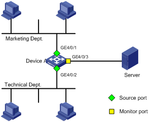
On a network shown in Figure 3,
· Device A connects to the marketing department through GigabitEthernet 4/0/1 and to the technical department through GigabitEthernet 4/0/2, and connects to the server through GigabitEthernet 4/0/3.
· Configure local port mirroring in source port mode to enable the server to monitor the bidirectional traffic of the marketing department and the technical department.
Configuration procedure
1. Configure a local mirroring group:
# Create a local mirroring group.
<Sysname> system-view
[Sysname] mirroring-group 1 local
# Configure ports GigabitEthernet 4/0/1 and GigabitEthernet 4/0/2 as mirroring ports and port GigabitEthernet 4/0/3 as the monitor port in the mirroring group.
[Sysname] mirroring-group 1 mirroring-port gigabitethernet 4/0/1 gigabitethernet 4/0/2 both
[Sysname] mirroring-group 1 monitor-port gigabitethernet 4/0/3
# Disable the spanning tree feature on the monitor port GigabitEthernet 4/0/3.
[DeviceA] interface Gigabitethernet 4/0/3
[DeviceA-Gigabitethernet4/0/3] undo stp enable
[DeviceA-Gigabitethernet4/0/3] quit
2. Verify the configuration:
# Display the configuration of all mirroring groups.
[DeviceA] display mirroring-group all
mirroring-group 1:
type: local
status: active
mirroring port:
Gigabitethernet4/0/1 both
Gigabitethernet4/0/2 both
mirroring vlan:
monitor port: Gigabitethernet4/0/3
After the configurations are completed, you can monitor all the packets received and sent by the marketing department and the technical department on the server.
Local port mirroring configuration example (in source VLAN mode)
Network requirements
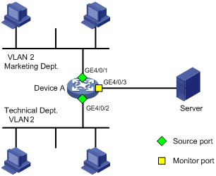
On a network shown in Figure 4:
· Device A connects to the marketing department through GigabitEthernet 4/0/1 and to the technical department through GigabitEthernet 4/0/2, and connects to the server through GigabitEthernet 4/0/3. GigabitEthernet 4/0/1 and GigabitEthernet 4/0/2 both belong to VLAN 2.
· Configure local port mirroring in source VLAN mode to enable the server to monitor the bidirectional traffic of the marketing department and the technical department.
Configuration procedure
1. Create a local mirroring group.
# Create local mirroring group 1
<DeviceA> system-view
[DeviceA] mirroring-group 1 local
# Create VLAN 2, and assign GigabitEthernet 4/0/1 and GigabitEthernet 4/0/2 to VLAN 2.
[DeviceA] vlan 2
[DeviceA-vlan2] port GigabitEthernet 4/0/1 GigabitEthernet 4/0/2
[DeviceA-vlan2] quit
# Configure VLAN 2 as a source VLAN and GigabitEthernet 4/0/3 as the monitor port.
[DeviceA] mirroring-group 1 mirroring-vlan 2 both
[DeviceA] mirroring-group 1 monitor-port GigabitEthernet 4/0/3
# Disable the spanning tree feature on the monitor port GigabitEthernet 4/0/3.
[DeviceA] interface GigabitEthernet 4/0/3
[DeviceA- GigabitEthernet4/0/3] undo stp enable
[DeviceA- GigabitEthernet4/0/3] quit
2. Verify the configuration.
# Display the configuration of all mirroring groups.
[DeviceA] display mirroring-group all
mirroring-group 1:
type: local
status: active
mirroring port:
mirroring vlan:
2 both
mirroring CPU:
monitor port: Gigabitethernet4/0/3
After the configurations are completed, you can monitor all the packets received and sent by the marketing department and the technical department on the server.
Layer 2 remote port mirroring configuration example (reflector port configurable)
Network requirements
As shown in Figure 5, Device A connects to the marketing department through GigabitEthernet 4/0/1, and to the trunk port GigabitEthernet 4/0/1 of Device B through the trunk port GigabitEthernet 4/0/2. Device C connects to the server through GigabitEthernet 4/0/2, and to the trunk port GigabitEthernet 4/0/2 of Device B through the trunk port GigabitEthernet 4/0/1. Device A supports configurable reflector port configuration.
Configure Layer 2 remote port mirroring to enable the server to monitor the bidirectional traffic of the marketing department.

Configuration procedure
1. Configure Device A (the source device):
# Create a remote source group.
<DeviceA> system-view
[DeviceA] mirroring-group 1 remote-source
# Create VLAN 2.
[DeviceA] vlan 2
[DeviceA-vlan2] quit
# Configure VLAN 2 as the remote probe VLAN, GigabitEthernet 4/0/1 as a source port, and GigabitEthernet 4/0/3 as the reflector port in the mirroring group.
[DeviceA] mirroring-group 1 remote-probe vlan 2
[DeviceA] mirroring-group 1 mirroring-port GigabitEthernet 4/0/1 both
[DeviceA] mirroring-group 1 reflector-port GigabitEthernet 4/0/3
# Configure GigabitEthernet 4/0/2 as a trunk port that permits the packets of VLAN 2 to pass through.
[DeviceA] interface GigabitEthernet 4/0/2
[DeviceA-GigabitEthernet 4/0/2] port link-type trunk
[DeviceA-GigabitEthernet 4/0/2] port trunk permit vlan 2
[DeviceA-GigabitEthernet 4/0/2] quit
# Disable the spanning tree feature on reflector port GigabitEthernet 4/0/3.
[DeviceA] interface GigabitEthernet 4/0/3
[DeviceA-GigabitEthernet 4/0/3] undo stp enable
[DeviceA-GigabitEthernet 4/0/3] quit
2. Configure Device B (the intermediate device):
# Create VLAN 2.
<DeviceB> system-view
[DeviceB] vlan 2
[DeviceB-vlan2] quit
# Configure GigabitEthernet 4/0/1 as a trunk port that permits the packets of VLAN 2 to pass through.
[DeviceB] interface GigabitEthernet 4/0/1
[DeviceB-GigabitEthernet 4/0/1] port link-type trunk
[DeviceB-GigabitEthernet 4/0/1] port trunk permit vlan 2
[DeviceB-GigabitEthernet 4/0/1] quit
# Configure GigabitEthernet 4/0/2 as a trunk port that permits the packets of VLAN 2 to pass through.
[DeviceB] interface GigabitEthernet 4/0/2
[DeviceB-GigabitEthernet 4/0/2] port link-type trunk
[DeviceB-GigabitEthernet 4/0/2] port trunk permit vlan 2
[DeviceB-GigabitEthernet 4/0/2] quit
3. Configure Device C (the destination device):
# Configure GigabitEthernet 4/0/1 as a trunk port that permits the packets of VLAN 2 to pass through.
<DeviceC> system-view
[DeviceC] interface GigabitEthernet 4/0/1
[DeviceC-GigabitEthernet 4/0/1] port link-type trunk
[DeviceC-GigabitEthernet 4/0/1] port trunk permit vlan 2
[DeviceC-GigabitEthernet 4/0/1] quit
# Create a remote destination group.
[DeviceC] mirroring-group 1 remote-destination
# Create VLAN 2.
[DeviceC] vlan 2
[DeviceC-vlan2] quit
# Configure VLAN 2 as the remote probe VLAN of the mirroring group and GigabitEthernet 4/0/2 as the monitor port of the mirroring group, disable the spanning tree feature on GigabitEthernet 4/0/2, and assign the port to VLAN 2.
[DeviceC] mirroring-group 1 remote-probe vlan 2
[DeviceC] interface GigabitEthernet 4/0/2
[DeviceC-GigabitEthernet 4/0/2] mirroring-group 1 monitor-port
[DeviceC-GigabitEthernet 4/0/2] undo stp enable
[DeviceC-GigabitEthernet 4/0/2] port access vlan 2
[DeviceC-GigabitEthernet 4/0/2] quit
4. Verify the configuration:
After the configurations are completed, you can monitor all the packets received and sent by the marketing department on the server.
Introduction
You can configure mirroring traffic to an interface, to a CPU, or to a VLAN.
· Mirroring traffic to an interface copies the matching packets to a destination interface.
· Mirroring traffic to a CPU copies the matching packets to a CPU (the CPU of the card where interfaces with traffic mirroring configured reside).
· Mirroring traffic to a VLAN copies the matching packets to a VLAN where the packets are broadcast.
|
|
NOTE: For more information about QoS policies, traffic classes, and traffic behaviors, see ACL and QoS Configuration Guide. |
Traffic mirroring configuration task list
Complete these tasks to configure traffic mirroring:
|
Task |
Remarks |
|
|
Required. |
||
|
Required. Perform one of these configurations. |
||
|
Required. |
||
|
Required. Select one application destination as needed. The base card supports both inbound and outbound traffic mirroring. The Ethernet interface card supports only inbound traffic mirroring. |
||
Configuring traffic mirroring
Configuration prerequisites
Before configuring traffic mirroring, configure ACLs first.
Configuring match criteria
To configure a packet match criterion:
|
Step |
Command |
Remarks |
|
1. Enter system view. |
system-view |
N/A |
|
2. Create a class and enter class view. |
traffic classifier tcl-name [ operator { and | or } ] |
By default, no traffic class exists. |
|
3. Configure the match criteria. |
if-match [ not ] match-criteria |
By default, no packet match criterion is configured in a traffic class. |
|
|
NOTE: For more information about the traffic classifier command and the if-match command, see ACL and QoS Command Reference. |
Configuring traffic mirroring of different types
|
|
NOTE: In a traffic behavior, the action of mirroring traffic to an interface, the action of mirroring traffic to a CPU, and the action of mirroring traffic to a VLAN are mutually exclusive. |
Mirroring traffic to an interface
To mirror traffic to an interface:
|
Step |
Command |
Remarks |
|
1. Enter system view. |
system-view |
N/A |
|
2. Create a behavior and enter behavior view. |
traffic behavior behavior-name |
By default, no traffic behavior exists. |
|
3. Specify the destination interface for traffic mirroring. |
mirror-to interface interface-type interface-number [ backup-interface interface-type interface-number ] |
By default, traffic mirroring is not configured in a traffic behavior. |
|
4. Configure a sampler referenced for traffic mirroring. |
mirror-to interface interface-type interface-number [ backup-interface interface-type interface-number ] sampler sampler-name |
Optional. Not configured by default. |
|
|
CAUTION: When you configure traffic mirroring to mirror traffic to a port of the OAA card, make sure that the port of the OAA card is in VLAN 1. |
|
|
NOTE: · For more information about the traffic behavior command, see ACL and QoS Command Reference. · For more information about samplers, see the chapter “Configuring samplers.” |
Mirroring traffic to a VLAN
To mirror traffic to a VLAN:
|
Step |
Command |
Remarks |
|
1. Enter system view. |
system-view |
N/A |
|
2. Create a behavior and enter behavior view. |
traffic behavior behavior-name |
By default, no traffic behavior exists. |
|
3. Mirror traffic to a VLAN. |
mirror-to vlan vlan-id |
By default, traffic mirroring is not configured in a traffic behavior. |
|
|
NOTE: · For more information about the traffic behavior command, see ACL and QoS Command Reference. · You can mirror traffic to a nonexistent VLAN. After you create the VLAN and assign some ports to it, traffic mirroring to the VLAN takes effect automatically. |
Mirroring traffic to the CPU
To mirror traffic to the CPU:
|
Step |
Command |
Remarks |
|
1. Enter system view. |
system-view |
N/A |
|
2. Create a behavior and enter behavior view. |
traffic behavior behavior-name |
By default, no traffic behavior exists. |
|
3. Mirror traffic to the CPU. |
mirror-to cpu |
By default, no traffic mirroring is configured in a traffic behavior. |
|
|
NOTE: · For more information about the traffic behavior command, see ACL and QoS Command Reference. · The CPU refers to the CPU of the card where interfaces with traffic mirroring configured reside. |
Configuring a QoS policy
To configure a QoS policy:
|
Step |
Command |
Remarks |
|
1. Enter system view. |
system-view |
N/A |
|
2. Create a policy and enter policy view. |
qos policy policy-name |
By default, no policy exists. |
|
3. Associate a class with a traffic behavior in the QoS policy. |
classifier tcl-name behavior behavior-name |
By default, no traffic behavior is associated with a class. |
|
|
NOTE: For more information about the qos policy and classifier behavior commands, see ACL and QoS Command Reference. |
Applying a QoS policy
|
|
NOTE: For more information about applying a QoS policy, see ACL and QoS Configuration Guide. |
Applying a QoS policy to an interface
By applying a QoS policy to an interface, you can regulate the traffic sent or received on the interface. A policy can be applied to multiple interfaces, but in one direction (inbound or outbound) of an interface, only one policy can be applied.
To apply a QoS policy to an interface:
|
Step |
Command |
Remarks |
|
1. Enter system view. |
system-view |
N/A |
|
2. Enter interface view. |
interface interface-type interface-number |
N/A |
|
3. Apply a QoS policy to the interface. |
qos apply policy policy-name { inbound | outbound } |
The outbound keyword is available only on the base card. |
|
|
NOTE: For more information about the qos apply policy command, see ACL and QoS Command Reference. |
Applying a QoS policy to a VLAN
You can apply a QoS policy to a VLAN to mirror the traffic in a specified direction on all ports.
To apply the QoS policy to a VLAN:
|
Step |
Command |
Remarks |
|
1. Enter system view. |
system-view |
N/A |
|
2. Apply a QoS policy to VLANs. |
qos vlan-policy policy-name vlan vlan-id-list { inbound | outbound } |
The outbound keyword is available only on the base card. |
|
|
NOTE: For more information about the qos vlan-policy command, see ACL and QoS Command Reference. |
Applying a QoS policy globally
You can apply a QoS policy globally to mirror the traffic in a specified direction on all ports.
To apply a QoS policy globally:
|
Step |
Command |
Remarks |
|
1. Enter system view. |
system-view |
N/A |
|
2. Apply a QoS policy globally. |
qos apply policy policy-name global { inbound | outbound } |
The outbound keyword is available only on the base card. |
|
|
NOTE: For more information about the qos apply policy command, see ACL and QoS Command Reference. |
Displaying and maintaining traffic mirroring
|
Task |
Command |
Remarks |
|
Display user-defined traffic behavior configuration information. |
display traffic behavior user-defined [ behavior-name ] [ | { begin | exclude | include } regular-expression ] |
Available in any view |
|
Display user-defined QoS policy configuration information. |
display qos policy user-defined [ policy-name [ classifier tcl-name ] ] [ | { begin | exclude | include } regular-expression ] |
Available in any view |
|
|
NOTE: For more information about the display traffic behavior and display qos policy commands, see ACL and QoS Command Reference. |
Traffic mirroring configuration example
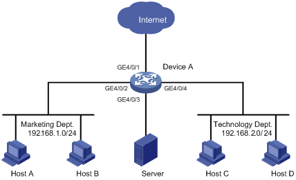
Network requirements
As shown in Figure 6, different departments of a company use IP addresses on different subnets. The marketing and technology departments use the IP addresses on subnets 192.168.1.0/24 and 192.168.2.0/24 respectively. The working hour of the company is from 8:00 to 18:00 on weekdays.
Configure traffic mirroring so that the server can monitor the traffic that the technology department sends to access the Internet, and IP traffic that the technology department sends to the marketing department.
Configuration procedure
1. Monitor the traffic sent by the technology department to access the Internet.
# Create ACL 3000 to allow packets from the technology department (on subnet 192.168.2.0/24) to access the Internet.
<DeviceA> system-view
[DeviceA] acl number 3000
[DeviceA-acl-adv-3000] rule permit tcp source 192.168.2.0 0.0.0.255 destination-port eq www
[DeviceA-acl-adv-3000] quit
# Create traffic class tech_c, and configure the match criterion as ACL 3000.
[DeviceA] traffic classifier tech_c
[DeviceA-classifier-tech_c] if-match acl 3000
[DeviceA-classifier-tech_c] quit
# Create traffic behavior tech_b, and configure the action of mirroring traffic to port GigabitEthernet 4/0/3.
[DeviceA] traffic behavior tech_b
[DeviceA-behavior-tech_b] mirror-to interface GigabitEthernet 4/0/3
[DeviceA-behavior-tech_b] quit
# Create QoS policy tech_p, and associate traffic class tech_c with traffic behavior tech_b in the QoS policy.
[DeviceA] qos policy tech_p
[DeviceA-qospolicy-tech_p] classifier tech_c behavior tech_b
[DeviceA-qospolicy-tech_p] quit
# Apply QoS policy tech_p to the incoming packets of GigabitEthernet 4/0/1.
[DeviceA] interface GigabitEthernet 4/0/1
[DeviceA-GigabitEthernet 4/0/1] qos apply policy tech_p inbound
[DeviceA-GigabitEthernet 4/0/1] quit
2. Monitor the traffic that the technology department sends to the marketing department.
# Configure a time range named work to cover the time from 8: 00 to 18: 00 in working days.
[DeviceA] time-range work 8:0 to 18:0 working-day
# Create ACL 3001 to allow packets sent from the technology department (on subnet 192.168.2.0/24) to the marketing department (on subnet 192.168.1.0/24).
[DeviceA] acl number 3001
[DeviceA-acl-adv-3001] rule permit ip source 192.168.2.0 0.0.0.255 destination 192.168.1.0 0.0.0.255 time-range work
[DeviceA-acl-adv-3001] quit
# Create traffic class mkt_c, and configure the match criterion as ACL 3001.
[DeviceA] traffic classifier mkt_c
[DeviceA-classifier-mkt_c] if-match acl 3001
[DeviceA-classifier-mkt_c] quit
# Create traffic behavior mkt_b, and configure the action of mirroring traffic to port GigabitEthernet 4/0/3.
[DeviceA] traffic behavior mkt_b
[DeviceA-behavior-mkt_b] mirror-to interface GigabitEthernet 4/0/3
[DeviceA-behavior-mkt_b] quit
# Create QoS policy mkt_p, and associate traffic class mkt_c with traffic behavior mkt_b in the QoS policy.
[DeviceA] qos policy mkt_p
[DeviceA-qospolicy-mkt_p] classifier mkt_c behavior mkt_b
[DeviceA-qospolicy-mkt_p] quit
# Apply QoS policy mkt_p to the incoming packets of GigabitEthernet 4/0/2.
[DeviceA] interface GigabitEthernet 4/0/2
[DeviceA-GigabitEthernet 4/0/2] qos apply policy mkt_p inbound
Verifying the configuration
After completing the configurations, through the server, you can monitor all traffic sent by the technology department to access the Internet and the IP traffic that the technology department sends to the marketing department during working hours.