- Table of Contents
- Related Documents
-
| Title | Size | Download |
|---|---|---|
| 02-HDLC Configuration | 168.47 KB |
Contents
HDLC frame format and frame type
Enabling HDLC encapsulation on an interface
Configuring an IP address for an interface
Configuring the link status polling interval
Configuring HDLC link bundling
Basic concepts of HDLC link bundling
Configuring an HDLC link bundle interface
Assigning an interface to an HDLC link bundle
Displaying and maintaining HDLC link bundling
HDLC link bundling configuration example
Introduction to HDLC
HDLC overview
High-level Data Link Control (HDLC) is a bit-oriented link layer protocol. Its most prominent feature is that it can transmit any types of bit stream transparently.
· HDLC supports point-to-point link only and does not support point-to-multipoint link.
· HDLC supports neither IP address negotiation nor authentication. It uses keepalive messages to check link status.
· HDLC works only on synchronous interfaces or synchronous/asynchronous interfaces in synchronous mode.
|
|
NOTE: The S9500E switch series supports HDLC encapsulation only on POS interfaces. |
HDLC frame format and frame type
There are three types of HDLC frames: information frame (I frame), supervision frame (S frame) and unnumbered frame (U frame).
· Information frame is responsible for transmitting useful data or information.
· Supervision frame is responsible for error control and flow control.
· Unnumbered frame is responsible for the link establishment, teardown, and so on.
An HDLC frame is composed of flag field, address field, control field, information field and checksum field.
· The flag field, 0111111, marks the beginning and end of an HDLC frame.
· The address field is eight bits; it identifies the source or destination where the frame is sent or received.
· The control field is eight bits; it identifies the control type and defines the frame type (control or data).
· The information field can be an arbitrary binary bit set. The minimum length can be zero and the maximum length is decided by the frame check sequence (FCS) field or the buffer size of the communicating node. Generally, the maximum length is between 1000 and 2000 bits.
· The checksum field can use a 16-bit cyclic redundancy check (CRC) to check the content of a frame.
Enabling HDLC encapsulation on an interface
To enable HDLC encapsulation on an interface:
|
Step |
Command |
Remarks |
|
1. Enter system view. |
system-view |
N/A |
|
2. Enter interface view. |
interface interface-type interface-number |
N/A |
|
3. Enable HDLC encapsulation on the interface. |
link-protocol hdlc |
PPP is the default. |
Configuring an IP address for an interface
To configure an IP address for an interface:
|
Step |
Command |
Remarks |
|
1. Enter system view. |
system-view |
N/A |
|
2. Enter interface view. |
interface interface-type interface-number |
N/A |
|
3. Configure an IP address for the interface. |
·
Assign an IP address to the interface: ·
Configure the interface as an IP unnumbered
interface to borrow the IP address of the specified interface: |
Use either approach. By default, no IP address is assigned to an interface, and an interface does not borrow the IP address of any other interface. |
Make sure that an IP unnumbered HDLC interface has a route to the remote end. When you configure the route, follow these guidelines:
· If you use a routing protocol, make sure that the learned route has a mask longer than the borrowed IP address, because route lookup is based on longest match.
· If you configure a static route, and the borrowed IP network mask is 32 bits long, the static route must use a mask shorter than the borrowed IP address.
· If you configure a static route, and the mask of the borrowed IP address is shorter than 32 bits, the static route must use a mask longer than the borrowed IP address.
|
|
NOTE: For more information about interface IP address configuration, see Layer 3—IP Services Configuration Guide. |
Configuring the link status polling interval
HDLC can regularly check link status. The link status polling interval is user configurable. It is a good practice to set the same interval for the two ends of a link. Setting the link status polling interval to 0 disables link status check. If the network has a long delay or is experiencing congestion, you can increase the polling interval to avoid network flappings.
To configure the link status polling interval:
|
Step |
Command |
Remarks |
|
1. Enter system view. |
system-view |
N/A |
|
2. Enter interface view. |
interface interface-type interface-number |
N/A |
|
3. Configure the link status polling interval. |
timer hold seconds |
Optional. The default interval is 10 seconds. |
HDLC configuration example
Network requirements
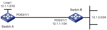
As shown in Figure 1, Switch A and Switch B are connected through their POS interfaces with HDLC enabled.
Configure POS 3/1/1 of Switch A to borrow the IP address of the local loopback interface, which has a 32-bit mask.
Configure Switch A to learn the routing information of Switch B through static routes, so that Switch A can reach the network segment 12.1.2.0/24.
Configuration procedure
1. Configure Switch A
<SwitchA> system-view
[SwitchA] interface LoopBack 1
[SwitchA-LoopBack1] ip address 12.1.1.2 32
[SwitchA-LoopBack1] quit
[SwitchA] interface Pos 3/1/1
[SwitchA-Pos3/1/1] link-protocol hdlc
[SwitchA-Pos3/1/1] ip address unnumbered interface LoopBack 1
[SwitchA-Pos3/1/1] quit
2. Configure Switch B
<SwitchB> system-view
[SwitchB] interface Pos 3/1/1
[SwitchB-Pos3/1/1] link-protocol hdlc
[SwitchB-Pos3/1/1] ip address 12.1.1.1 24
3. Configure two static routes on Switch A
[SwitchA] ip route-static 12.1.1.0 24 Pos 3/1/1
[SwitchA] ip route-static 12.1.2.0 24 12.1.1.1
4. Verify that Switch A can ping the network 12.1.2.0/24.
[SwitchA] ping 12.1.2.1
PING 12.1.2.1: 56 data bytes, press CTRL_C to break
Reply from 12.1.2.1: bytes=56 Sequence=1 ttl=255 time=35 ms
Reply from 12.1.2.1: bytes=56 Sequence=2 ttl=255 time=1 ms
Reply from 12.1.2.1: bytes=56 Sequence=3 ttl=255 time=10 ms
Reply from 12.1.2.1: bytes=56 Sequence=4 ttl=255 time=1 ms
Reply from 12.1.2.1: bytes=56 Sequence=5 ttl=255 time=1 ms
--- 12.1.2.1 ping statistics ---
5 packet(s) transmitted
5 packet(s) received
0.00% packet loss
round-trip min/avg/max = 1/9/35 ms
# Execute the display ip routing-table command on Switch A to view the routing table.
[SwitchA] display ip routing-table
Routing Tables: Public
Destinations : 5 Routes : 5
Destination/Mask Proto Pre Cost NextHop Interface
12.1.1.0/24 Static 60 0 12.1.1.2 POS3/1/1
12.1.1.2/32 Direct 0 0 127.0.0.1 InLoop0
12.1.2.0/24 Static 60 0 12.1.1.1 POS3/1/1
127.0.0.0/8 Direct 0 0 127.0.0.1 InLoop0
127.0.0.1/32 Direct 0 0 127.0.0.1 InLoop0
Overview
HDLC link bundling allows you to bundle multiple interfaces that use HDLC encapsulation together to form one logical link.
HDLC link bundling delivers the following benefits:
· Load balancing: Incoming/outgoing traffic is distributed across multiple member interfaces of the HDLC link bundle.
· Increased bandwidth: The bandwidth on the HDLC link bundle interface is the total bandwidth of all available member interfaces.
· Improved connection reliability: When a member interface goes down, the traffic on it automatically switches over to other available member interfaces. This avoids service interruption and improves the connection reliability of the whole HDLC link bundle.
Basic concepts of HDLC link bundling
HDLC link bundle interface
An HDLC link bundle interface is a logical interface corresponding to a bundle of HDLC links.
HDLC link bundle
An HDLC link bundle is a group of HDLC interfaces. When you create an HDLC link bundle interface, an HDLC link bundle numbered the same is automatically generated.
To bring up an HDLC link bundle, it must meet the requirements for the minimum number of selected links (if set) and minimum amount of bandwidth (if set).
Member interface
An interface assigned to an HDLC link bundle is called an HDLC link bundle member interface.
Only POS interfaces can be assigned to HDLC link bundles.
Bundling priority
When the number of active member interfaces in an HDLC link bundle is limited, only the higher-priority links within the bundle are active. A lower bundling priority value is a higher priority. Configure a higher priority on the link you want to configure as the active link.
States of member interfaces
An HDLC link bundle member interface can be in one of the following states:
· Initial—The member interface is down at the link layer.
· Negotiated—The member interface is up at the link layer, but does not meet the conditions for being a selected interface in the HDLC link bundle.
· Ready—The member interface is up at the link layer and meets the conditions for being a selected interface, but is not selected yet due to the limitation on the maximum number of selected member interfaces, the minimum number of selected member interfaces required to bring up the HDLC link bundle, or the minimum amount of bandwidth required to bring up the HDLC link bundle.
· Selected—The member interface is up at the link layer, meets the conditions for being a selected interface, and conforms to the restrictions mentioned above. Only member interfaces in this state can forward traffic. The switch allows interfaces with different rates to be selected at the same time. However, the transmission capability of each selected interface is that of the lowest-rate interface. For example, if you assign a 155-Mbps POS interface and a 622-Mbps POS interface to an HDLC link bundle, the transmission capability of the 622-Mbps POS interface is 155 Mbps, and the transmission capability of the HDLC link bundle is (150 + 150) = 310 Mbps, rather than (150 + 622) = 777 Mbps. H3C does not recommend assigning interfaces with different rates to the same HDLC link bundle.
For more information about how to determine the state of a member interface, see “How the switch determines the state of a member interface.”
How HDLC link bundling works
How the switch determines the state of a member interface
The states of HDLC link bundle member interfaces are determined as follows:
1. An interface is placed in initial state if its link layer protocol is down.
2. An interface is placed in negotiated state when its link layer protocol goes up.
3. An interface in negotiated state may transit to the selected or ready state after undergoing a selection process. Suppose M member interfaces are selected:
¡ If the number of selected member interfaces is not restricted, the M member interfaces enter the selected state.
¡ If the maximum number of selected member interfaces is N on the switch: when N is no smaller than M, all the M member interfaces enter the selected state; when N is smaller than M, the member interfaces are first sorted in the descending order of rates/baud rates, member interfaces with the same rate/baud rate are sorted in the descending order of bundling priorities, and member interfaces with the same bundling priority are sorted in the ascending order of index numbers. The first N member interfaces enter the selected state, and the remaining (M-N) member interfaces enter the ready state.
4. Suppose the number of member interfaces meet the above conditions for being selected is P. If the number of selected member interfaces required to bring up the HDLC link bundle is set to Q and P is smaller than Q, none of the P member interfaces will be selected. Instead, they all stay in the ready state. The same situation occurs when the sum of bandwidths of the P member interfaces is smaller than the minimum amount of bandwidth required to bring up the HDLC link bundle.
If an HDLC link bundle does not contain any selected member interfaces, the HDLC link bundle interface is brought down, and cannot forward traffic. It will not be brought up and forward traffic until selected member interfaces are detected in the HDLC link bundle. The bandwidth of an HDLC link bundle is the total bandwidth of all selected member interfaces.
|
|
NOTE: The maximum number of member interfaces that can be selected in a bundle is set by the bundle max-active links command. If the command is not set, a bundle can have a maximum of eight selected interfaces. |
Load balancing modes
An HDLC link bundle forwards traffic through its selected member interfaces. When multiple selected member interfaces exist in an HDLC link bundle, the switch chooses some of the selected member interfaces to forward traffic according to its load balancing mode. Two load balancing modes are available:
· Per-flow load balancing—Packets of the same flow are forwarded on the same selected member interface. A flow is identified by an IP quintuple of source IP address, destination IP address, protocol ID, source port, and destination port.
· Per-packet load balancing—Packets are distributed evenly across all selected member interfaces in a round-robin way.
|
|
NOTE: The S9500E switches support only per-flow load balancing. |
Configuring an HDLC link bundle interface
To configure an HDLC link bundle interface:
|
Step |
Command |
Remarks |
|
1. Enter system view. |
system-view |
N/A |
|
1. Create an HDLC link bundle interface and enter its view. |
interface hdlc-bundle bundle-id |
N/A |
|
2. Assign an IP address to the HDLC link bundle interface. |
ip address ip-address { mask | mask-length } [ sub ] |
By default, no IP address is assigned to an HDLC link bundle interface. |
|
3. Set the minimum number of selected member interfaces required to bring up the HDLC link bundle. |
bundle min-active links number |
Optional. Not specified by default. |
|
4. Limit the number of selected member interfaces in the HDLC link bundle. |
bundle max-active links number |
Optional. Not specified by default. |
|
5. Specify the minimum amount of bandwidth required to bring up the HDLC link bundle. |
bundle min-active bandwidth bandwidth |
Optional. Not specified by default. |
|
6. Configure a description for the HDLC link bundle interface. |
description text |
Optional. By default, the description of an HDLC link bundle interface is the interface name followed by the Interface string. |
|
7. Specify the MTU size on the HDLC link bundle interface. |
mtu size |
Optional. 1500 bytes by default. The MTU size specified here affects the fragmentation and reassembly of IP packets. Use this command to set a proper MTU size according to your network conditions. |
|
8. Restore the default settings for the HDLC link bundle interface. |
default |
Optional. |
|
9. Enable the HDLC link bundle interface. |
undo shutdown |
Optional. Enabled by default. Enabling/disabling an HDLC link bundle interface does not enable or disable any member interface in the HDLC link bundle but may affect the selected states of the member interfaces. |
|
|
CAUTION: · The number of selected member interfaces required to bring up an HDLC link bundle should be no bigger than the limit on the number of selected member interfaces in the HDLC link bundle. · To guarantee normal traffic transmission, on the HDLC link bundle interfaces on both ends of an HDLC link bundle, configure the same parameters, including the number of selected member interfaces required to bring up the HDLC link bundle, limit on the number of selected member interfaces in the HDLC link bundle, and minimum amount of bandwidth required to bring up the HDLC link bundle. · For more information about the ip address command, see Layer 3—IP Services Command Reference. |
Assigning an interface to an HDLC link bundle
To assign an interface to an HDLC link bundle:
|
Step |
Command |
Remarks |
|
1. Enter system view. |
system-view |
N/A |
|
2. Enter POS interface view. |
interface interface-type interface-number |
N/A |
|
3. Set the link layer protocol of the interface to HDLC. |
link-protocol hdlc |
PPP by default. |
|
4. Assign the interface to an HDLC link bundle. |
bundle id bundle-id |
N/A |
|
5. Set the bundling priority for the member interface. |
bundle member-priority priority |
Optional. The default setting is 32768. |
|
|
CAUTION: · You cannot assign interfaces configured with the following features to an HDLC link bundle: IPv4 addresses, IP unnumbered, IPv6 addresses, and URPF. After an interface is assigned to an HDLC link bundle, you cannot configure any of these features on the interface either. · An interface can belong to only one HDLC link bundle at any point in time. To assign an HDLC link bundle member interface to another HDLC link bundle, remove the interface from the current HDLC link bundle first. · The link layer protocol of an interface to be assigned to an HDLC link bundle can only be HDLC. After the interface is assigned to the HDLC link bundle, you are not allowed to change its link layer protocol. · You can assign interfaces to a nonexistent HDLC link bundle as members. · You can assign interfaces on different cards to the same HDLC link bundle. · If you change the bundling priority of a member interface after the HDLC link bundle configuration is finished, the switch will determine the state of each member interface in the HDLC link bundle again. · Before you assign an interface to an HDLC link bundle, do not configure Layer 3 features, such as MPLS and VPN, on the interface. If the interface has been configured with Layer 3 features, remove the Layer 3 feature configuration first. After you assign an interface to an HDLC link bundle, you can configure Layer 3 features only on the HDLC link bundle interface. If you mistakenly configure Layer 3 features on a member interface, remove the Layer 3 feature configuration from the member interface first, and then use the shutdown and undo shutdown commands on the HDLC link bundle interface to completely remove the configuration. · The peer interface directly connected to an HDLC link bundle member interface must also join the HDLC link bundle. · The bundle member-priority command and the bundle max-active links command usually need to be used in conjunction, so that interconnected interfaces on two different switches can be both selected at the same time and thus exchange traffic successfully. |
Displaying and maintaining HDLC link bundling
|
Task |
Command |
Remarks |
|
display bundle member hdlc-bundle [ bundle-id ] [ slot slot-number ] [ | { begin | exclude | include } regular-expression ] |
Available in any view |
|
|
Display information about an HDLC link bundle interface. |
display interface hdlc-bundle bundle-id [ brief ] [ | { begin | exclude | include } regular-expression ] display interface [ hdlc-bundle ] [ brief [ down ] ] [ | { begin | exclude | include } regular-expression ] |
Available in any view |
|
Clear statistics for an HDLC link bundle interface. |
reset counters interface [ hdlc-bundle [ bundle-id ] ] |
Available in user view |
HDLC link bundling configuration example
|
|
NOTE: By default, Ethernet, VLAN, and aggregate interfaces are in DOWN state. Before configuring these interfaces, use the undo shutdown command to bring them up. |
Network requirements
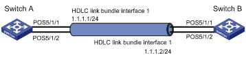
As shown in Figure 2, create an HDLC link bundle between Switch A and Switch B to increase bandwidth and enhance connection reliability between Switch A and Switch B.
Configuration procedure
1. Configure Switch A
# Create HDLC link bundle interface 1 and assign an IP address for it.
<SwitchA> system-view
[SwitchA] interface Hdlc-bundle 1
[SwitchA-Hdlc-bundle1] ip address 1.1.1.1 24
[SwitchA-Hdlc-bundle1] quit
# Assign POS interfaces POS 5/1/1 and POS 5/1/2 to HDLC link bundle 1. Configure the clock mode of these POS interfaces as master.
[SwitchA] interface Pos 5/1/1
[SwitchA-Pos5/1/1] clock master
[SwitchA-Pos5/1/1] link-protocol hdlc
[SwitchA-Pos5/1/1] bundle id 1
[SwitchA-Pos5/1/1] quit
[SwitchA] interface Pos 5/1/2
[SwitchA-Pos5/1/2] clock master
[SwitchA-Pos5/1/2] link-protocol hdlc
[SwitchA-Pos5/1/2] bundle id 1
[SwitchA-Pos5/1/2] quit
2. Configure Switch B
# Create HDLC link bundle interface 1 and assign an IP address for it.
<SwitchB> system-view
[SwitchB] interface Hdlc-bundle 1
[SwitchB-Hdlc-bundle1] ip address 1.1.1.2 24
[SwitchB-Hdlc-bundle1] quit
# Assign POS interfaces POS 5/1/1 and POS 5/1/2 to HDLC link bundle 1.
[SwitchB] interface Pos 5/1/1
[SwitchB-Pos5/1/1] link-protocol hdlc
[SwitchB-Pos5/1/1] bundle id 1
[SwitchB-Pos5/1/1] quit
[SwitchB] interface Pos 5/1/2
[SwitchB-Pos5/1/2] link-protocol hdlc
[SwitchB-Pos5/1/2] bundle id 1
[SwitchB-Pos5/1/2] quit
3. Verify the configuration
Use the display interface hdlc-bundle command on Switch A or Switch B to verify that the state of HDLC link bundle interface 1 is UP.
Take the output on Switch A for example.
[SwitchA] display interface Hdlc-bundle 1
Hdlc-bundle1 current state: UP
Line protocol current state: UP
Description: Hdlc-bundle1 Interface
The Maximum Transmit Unit is 1500
Internet Address is 1.1.1.1/24 Primary
Link layer protocol is HDLC
Physical is HDLC-BUNDLE, baudrate: 155520 kbps
Output queue : (Urgent queuing : Size/Length/Discards) 0/100/0
Output queue : (Protocol queuing : Size/Length/Discards) 0/500/0
Output queue : (FIFO queuing : Size/Length/Discards) 0/75/0
Last clearing of counters: Never
Last 300 seconds input rate: 0 bytes/sec, 0 bits/sec, 0 packets/sec
Last 300 seconds output rate: 0 bytes/sec, 0 bits/sec, 0 packets/sec
0 packets input, 0 bytes, 0 drops
0 packets output, 0 bytes, 0 drops
Verify that the HDLC link bundle interfaces on Switch A and Switch B can ping each other.
[SwitchA] ping –a 1.1.1.1 1.1.1.2
PING 1.1.1.2: 56 data bytes, press CTRL_C to break
Reply from 1.1.1.2: bytes=56 Sequence=1 ttl=255 time=6 ms
Reply from 1.1.1.2: bytes=56 Sequence=2 ttl=255 time=3 ms
Reply from 1.1.1.2: bytes=56 Sequence=3 ttl=255 time=3 ms
Reply from 1.1.1.2: bytes=56 Sequence=4 ttl=255 time=3 ms
Reply from 1.1.1.2: bytes=56 Sequence=5 ttl=255 time=3 ms
--- 1.1.1.2 ping statistics ---
5 packet(s) transmitted
5 packet(s) received
0.00% packet loss
round-trip min/avg/max = 3/3/6 ms