- Table of Contents
- Related Documents
-
| Title | Size | Download |
|---|---|---|
| 01-PPP Configuration | 233.08 KB |
Contents
Configuring PAP authentication
Configuring CHAP authentication
Configuring MS-CHAP or MS-CHAP-V2 authentication
One-way PAP authentication configuration example
Two-way PAP authentication configuration example
One-way CHAP authentication configuration example
Troubleshooting PPP configuration
A link cannot revert to the up state
A link remains down after IPv6CP negotiation fails
Introduction to PPP
Point-to-Point Protocol (PPP) is a link layer protocol that carries network layer packets over point-to-point links. It gains popularity because it provides user authentication, supports synchronous/asynchronous communication, and allows for easy extension.
PPP contains a set of protocols, including a link control protocol (LCP), a network control protocol (NCP), and authentication protocols such as Password Authentication Protocol (PAP), Challenge Handshake Authentication Protocol (CHAP), Microsoft CHAP (MS-CHAP), and Microsoft CHAP Version 2 (MS-CHAP-V2). Among these protocols,
· LCP establishes, tears down, and monitors data links.
· NCPs negotiate the formats and types of data packets transmitted on data links.
· PAP, CHAP, MS-CHAP, and MS-CHAP-V2 secure the network.
PAP authentication
PAP is a two-way handshake authentication protocol using plain text passwords. It operates as follows.
1. The requester sends its username and password to the authenticator.
2. The authenticator then checks the local user list to see if the username and password are correct and returns an acknowledgement or negative acknowledge.
Figure 1 PAP authentication
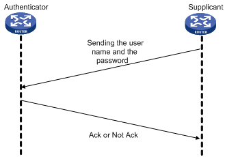
During PAP authentication, the password is transmitted on the link in plain text. In addition, the supplicant sends the username and the password repeatedly through the established PPP link until the authentication is over. Therefore, PAP is not a secure authentication protocol. It cannot prevent attacks.
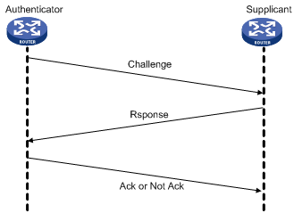
CHAP authentication
CHAP is a three-way handshake authentication protocol using cipher text password.
Currently, two types of CHAP authentication exist: one-way CHAP authentication and two-way CHAP authentication. By one-way CHAP authentication, one side of the link acts as the authenticator and the other acts as the supplicant. By two-way authentication, each side serves as both the authenticator and the supplicant. Normally, one-way CHAP authentication is adopted.
In one-way CHAP authentication, the authenticator may or may not be configured with a username. It is recommended that you configure a username for the authenticator, which makes it easier to identify the authenticator.
If the authenticator is configured with a username, CHAP authentication is performed as follows:
1. The authenticator initiates an authentication by sending a randomly-generated packet (Challenge) to the supplicant. The packet carries the local username with it in addition.
2. When the supplicant receives the authentication request, it searches the local user list for the password of the username carried in the received packet, encrypts the packet by using the MD5 algorithm, with the packet ID and the password as the parameters, and then sends the encrypted packet and the local username to the authenticator (Response).
3. The authenticator encrypts the original randomly-generated packet by using the MD5 algorithm, with the password of the supplicant it maintains as the parameter, compares the encrypted packet with the one received from the supplicant, and returns an Acknowledge or Not Acknowledge packet depending on the comparison result.
If the authenticator is not configured with a username, the CHAP authentication is performed as follows:
1. The authenticator initiates an authentication by sending a randomly-generated packet (Challenge) to the supplicant.
2. When the supplicant receives the authentication request, it encrypts the packet by using the MD5 algorithm, with the packet ID and the default CHAP password as the parameters, and then sends the encrypted packet and its own username to the authenticator (Response).
3. The authenticator encrypts the original randomly-generated packet by using the MD5 algorithm, with the password of the supplicant it maintains as the parameter, compares the encrypted packet with the one received from the supplicant, and returns an Acknowledge or Not Acknowledge packet depending on the comparison result.
Figure 2 CHAP authentication
MS-CHAP authentication
MS-CHAP is a three-way handshake authentication protocol using cipher text password.
Different from CHAP, MS-CHAP is enabled by negotiating CHAP Algorithm 0x80 in LCP option 3. Authentication Protocol, and MS-CHAP provides the authenticator-controlled authentication retry mechanism.
MS-CHAP authentication operates in the following workflow:
1. The authenticator initiates an authentication by sending a randomly-generated packet (Challenge) to the supplicant.
2. When the supplicant receives the authentication request, it encrypts the packet and its own password by using the 0x80 algorithm, and then sends the encrypted packet and its own username to the authenticator (Response).
3. When receiving the Response packet, the authenticator searches the local user list for the password of the username carried in the Response packet, encrypts the packet and the supplicant’s password by using the 0x80 algorithm, with the Challenge packet and the password as the parameters, compares the encrypted packet with the one received from the supplicant, and returns an Acknowledge or Not Acknowledge packet depending on the comparison result.
¡ If the authentication succeeds, the Acknowledge packet carries the greeting information.
¡ If the authentication fails, the Not Acknowledge packet carries errors, retry flag, and new randomly-generated packet (Challenge).
4. When the supplicant receives an Acknowledge packet, the authentication succeeds.
5. When the supplicant receives a Not Acknowledge packet that carries the retry (R) flag set to 1, the supplicant encrypts the Challenge packet and its own password by using the 0x80 algorithm, and sends the encrypted packet and its own username to the authenticator. The authenticator re-authenticates the Response packet. If the R flag in the packet is 0, the authentication fails and the authenticator disconnects from the supplicant. The authenticator allows the supplicant to retry for three times.
MS-CHAP-V2
MS-CHAP-V2 is a three-way handshake authentication protocol using cipher text password.
Different from CHAP, MS-CHAP-V2 is enabled by negotiating CHAP Algorithm 0x81 in LCP option 3, Authentication Protocol, provides mutual authentication between peers by piggybacking a peer challenge on the Response packet and an authenticator response on the Acknowledge packet, and supports the authentication retry and password changing mechanisms.
MS-CHAP-V2 authentication operates in the following workflow:
1. The authenticator initiates an authentication by sending a randomly-generated packet (Challenge) to the supplicant.
2. When the supplicant receives the authentication request, it encrypts the Challenge packet, its own randomly-generated packet (Peer-Challenge), its own username, and password by using the 0x81 algorithm, and then sends the encrypted packet and username to the authenticator (Response).
3. When receiving the Response packet, the authenticator encrypts the supplicant’s Peer-Challenge packet, the Challenge packet, and supplicant’s username and password by using the 0x81 algorithm. The authenticator compares the encrypted packet with the one received from the supplicant, and returns an Acknowledge or Not Acknowledge packet depending on the comparison result.
¡ If the authentication succeeds, the Acknowledge packet carries the encrypted packet from the supplicant for piggybacking authentication. The encrypted packet is generated by using the 0x81 algorithm, with the supplicant’s username and password, the encrypted packet received from the supplicant, the Peer-Challenge packet, and the Challenge packet as the parameters.
¡ If the authentication fails, the Not Acknowledge packet carries error code, retry flag, and new randomly-generated packet (Challenge).
4. When the supplicant receives an Acknowledge packet, it encrypts a packet by using the 0x81 algorithm, with its own username and password, the Challenge packet, Peer-Challenge packet, and the encrypted packet sent to the authenticator as the parameters. The supplicant compares the encrypted packet with the one sent to the authenticator. If they match each other, the authentication succeeds. If not, the link is disconnected.
5. When the supplicant receives a Not Acknowledge packet from the authenticator:
¡ If the error in the packet is due to password expiration, the supplicant encrypts a packet by using the 0x81 algorithm, with a new password, the Challenge packet, Peer-Challenge packet, and its own username as the parameters, and sends the encrypted packet and new password after encryption (change password) to the authenticator. The authenticator re-authenticates the supplicant by using the new password.
¡ If the R flag in the Not Acknowledge packet is 1, the supplicant encrypts a packet by using the 0x81 algorithm, with the Challenge packet, Peer-Challenge packet, its own username and password as the parameters, and sends the encrypted packet and its own username to the authenticator. The authenticator re-authenticates the supplicant by using the encrypted packet. If the R flag in the Not Acknowledge packet is 0, the link is disconnected. The authenticator allows the supplicant to retry for three times.
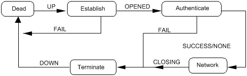
PPP link phases
Figure 3 illustrates the PPP operating mechanism with the following workflow:
1. A PPP link is in the Establish phase when it is about to be established. In this phase, LCP negotiation is performed, where LCP-related settings are determined, including operating mode (SP or MP), the authentication mode, and the Maximum Transmission Unit (MTU). If the negotiation is successful, the link enters the Opened state, indicating that the underlying layer link has been established.
2. If the authentication (the remote verifies the local or the local verifies the remote) is configured, the PPP link goes to the Authenticate phase, where PAP, CHAP, MS-CHAP, or MS-CHAP-V2 authentication is performed.
3. If the supplicant fails to pass the authentication, the link goes to the Terminate phase, where the link is torn down and LCP goes down. If the supplicant passes the authentication, the link goes to the Network phase. In this phase, NCP negotiation is performed, the LCP state remains Opened, and the state of the IP Control Protocol (IPCP) is changed from Initial to Request.
4. NCP negotiation supports the negotiation of IPCP, through which the IP addresses of both sides can be determined. NCP negotiation also determines and configures the network layer protocol to be used. A PPP link can carry a network layer protocol only after the NCP negotiation is successful.
5. After the NCP negotiation is performed, the PPP link remains active until an LCP or NCP frame close it explicitly or some external events take place (for example, the intervention of a user).
Figure 3 PPP operation flow chart
For more information about PPP, see RFC 1661.
Configuring PPP
|
|
NOTE: Only POS interfaces support PPP configuration. |
Configuration procedure
To configure PPP:
|
Step |
Command |
Remarks |
|
1. Enter system view. |
system-view |
N/A |
|
2. Enter interface view. |
interface interface-type interface-number |
N/A |
|
3. Configure the data link layer protocol. |
link-protocol { hdlc | ppp } |
Optional. By default, PPP is used. |
|
4. Set the polling interval. |
timer hold seconds |
Optional. 10 seconds by default |
|
5. Configure PPP authentication mode. |
·
Employ PAP: ·
Employ CHAP: ·
Employ MS-CHAP or MS-CHAP-V2: |
Optional. Use one approach. You can configure several authentication modes simultaneously. In LCP negotiation, the authenticator negotiates with the supplicant in the sequence of configured authentication modes until the LCP negotiation succeeds. If the response packet from the supplicant carries a recommended authentication mode, the authenticator directly uses the authentication mode if it finds the mode configured. PPP authentication is disabled by default. |
|
6. Configure PPP negotiation. |
See “Configuring PPP negotiation.” |
Optional. |
|
|
NOTE: This chapter only discusses local authentication. For more information about remote AAA authentication, see Security Configuration Guide. |
Configuring PAP authentication
Configuring the authenticator
To configure the authenticator:
|
Step |
Command |
Remarks |
|
1. Enter system view. |
system-view |
N/A |
|
2. Enter interface view. |
interface interface-type interface-number |
N/A |
|
3. Configure the local switch to authenticate the peer by using PAP. |
ppp authentication-mode pap [ [ call-in ] domain isp-name ] |
By default, PPP authentication is not performed. |
|
4. Return to system view. |
quit |
N/A |
|
5. Create a local user account for the supplicant and enter local user view. |
local-user username |
N/A |
|
6. Configure a password for the local user. |
password [ cipher | simple ] password |
N/A |
|
7. Configure the service type of the local user as PPP. |
service-type ppp |
N/A |
|
8. Return to system view. |
quit |
N/A |
|
9. Create an ISP domain or enter an existing ISP domain view. |
domain isp-name |
Optional. To configure the ppp authentication-mode command with an ISP domain specified which is not the default domain system, configure this command before configuring the ppp authentication-mode command. |
|
10. Configure local authentication for the PPP users. |
authentication ppp local |
Optional. |
|
|
NOTE: For more information about local user and domain configuration, see Security Configuration Guide. |
Configuring the supplicant
To configure the supplicant:
|
Step |
Command |
Remarks |
|
1. Enter system view. |
system-view |
N/A |
|
2. Enter interface view. |
interface interface-type interface-number |
N/A |
|
3. Configure the PAP username and password sent by the local switch to the peer when the local switch is authenticated by the peer by using PAP. |
ppp pap local-user username password { cipher | simple } password |
By default, when being authenticated by the peer by using PAP, the local switch sends null username and password to the peer. |
Configuring CHAP authentication
Depending on whether the authenticator is configured with a username or not, the configuration of CHAP authentication falls into the following two types:
· Configuring CHAP authentication when the authenticator name is configured
· Configuring CHAP authentication when no authenticator name is configured
Configuring CHAP authentication when the authenticator name is configured
1. Configuring the authenticator
To configure the authenticator:
|
Step |
Command |
Remarks |
|
1. Enter system view. |
system-view |
N/A |
|
2. Enter interface view. |
interface interface-type interface-number |
N/A |
|
3. Configure the local switch to authenticate the peer by using CHAP. |
ppp authentication-mode chap [ [ call-in ] domain isp-name ] |
By default, PPP authentication is disabled. |
|
4. Assign a username to the CHAP authenticator. |
ppp chap user username |
The username you assign to the authenticator here must be the same as the local username you assign to the authenticator on the supplicant. |
|
5. Return to system view. |
quit |
N/A |
|
6. Create a local user account for the supplicant and enter local user view. |
local-user username |
N/A |
|
7. Configure the password for the local user. |
password { cipher | simple } password |
The password configured on the authenticator must be the same as the one configured on the supplicant. |
|
8. Configure the service type of the local user as PPP. |
service-type ppp |
N/A |
|
9. Return to system view. |
quit |
N/A |
|
10. Create an ISP domain, or enter an existing ISP domain view. |
domain isp-name |
Optional. To configure the ppp authentication-mode command with an ISP domain specified which is not the default domain system, configure this command before configuring the ppp authentication-mode command. |
|
11. Configure local authentication for the PPP users. |
authentication ppp local |
Optional. |
|
|
NOTE: For more information about local user and domain configuration, see Security Configuration Guide. |
2. Configuring the supplicant
To configure the supplicant:
|
Step |
Command |
Remarks |
|
1. Enter system view. |
system-view |
N/A |
|
2. Enter interface view. |
interface interface-type interface-number |
N/A |
|
3. Assign a username to the CHAP supplicant. |
ppp chap user username |
The username you assign to the supplicant here must be the same as the local username you assign to the supplicant on the authenticator. |
|
4. Create a local user account for the authenticator and set the password. |
1.
Return to system view: 2.
Create a local user account for the
authenticator and enter local user view: 3.
Set the password: 4.
Configure the service type of the local
user as PPP: |
N/A |
|
|
NOTE: · For more information about local user configuration, see Security Configuration Guide. · If the authenticator name is configured, do not configure the ppp chap password command on the interface that connects the authenticatee. Otherwise, the authentication may fail. |
Configuring CHAP authentication when no authenticator name is configured
1. Configuring the authenticator
To configure the authenticator:
|
Step |
Command |
Remarks |
|
1. Enter system view. |
system-view |
N/A |
|
2. Enter interface view. |
interface interface-type interface-number |
N/A |
|
3. Configure the local switch to authenticate the peer by using CHAP. |
ppp authentication-mode chap [ [ call-in ] domain isp-name ] |
By default, PPP authentication is not performed. |
|
4. Return to system view. |
quit |
N/A |
|
5. Create a local user account for the supplicant and enter local user view. |
local-user username |
N/A |
|
6. Configure the password for the local user. |
password { cipher | simple } password |
N/A |
|
7. Configure the service type of the local user as PPP. |
service-type ppp |
N/A |
|
8. Return to system view. |
quit |
N/A |
|
9. Create an ISP domain, or enter an existing ISP domain view. |
domain isp-name |
Optional. To configure the ppp authentication-mode command with an ISP domain specified which is not the default domain system, configure this command before configuring the ppp authentication-mode command. |
|
10. Configure local authentication for the PPP users. |
authentication ppp local |
Optional. |
|
|
NOTE: For more information about local user and domain configuration, see Security Configuration Guide. |
2. Configuring the supplicant
To configure the supplicant:
|
Step |
Command |
Remarks |
|
1. Enter system view. |
system-view |
N/A |
|
2. Enter interface view. |
interface interface-type interface-number |
N/A |
|
3. Assign a username to the CHAP supplicant. |
ppp chap user username |
The username you assign to the supplicant here must be the same as the local username you assign to the supplicant on the authenticator. |
|
4. Set the default CHAP authentication password. |
ppp chap password { cipher | simple } password |
N/A |
Configuring MS-CHAP or MS-CHAP-V2 authentication
|
|
NOTE: · In MS-CHAP or MS-CHAP-V2 authentication, the authenticator must be an H3C device · Password change in MS-CHAP-V2 authentication does not support local authentication, but is used only in RADIUS authentication. |
To configure the authenticator for MS-CHAP or MS-CHAP-V2 authentication:
|
Step |
Command |
Remarks |
|
1. Enter system view. |
system-view |
N/A |
|
2. Enter interface view. |
interface interface-type interface-number |
N/A |
|
3. Configure the local device to authenticate the peer by using MS-CHAP or MS-CHAP-V2. |
ppp authentication-mode { ms-chap | ms-chap-v2 } [ [ call-in ] domain isp-name ] |
By default, PPP authentication is disabled. |
|
4. Return to system view. |
quit |
N/A |
|
5. Create a local user account for the authenticatee and enter local user view. |
local-user username |
N/A |
|
6. Set the password for the local user. |
password { cipher | simple } password |
N/A |
|
7. Set the service type of the local user to PPP. |
service-type ppp |
N/A |
|
8. Return to system view. |
quit |
N/A |
|
9. Create an ISP domain, or enter an existing ISP domain view. |
domain isp-name |
Optional. To configure the ppp authentication-mode command with an ISP domain specified which is not the default domain system, configure this command before configuring the ppp authentication-mode command. |
|
10. Configure local authentication for the PPP users. |
authentication ppp local |
Optional. |
|
|
NOTE: For how to create the local user and the ISP domain, and set their attributes, see Security Configuration Guide. |
Configuring PPP negotiation
Introduction to PPP negotiation parameters
PPP negotiation parameters that can be configured include:
· Negotiation timeout time
· IP address negotiation
1. Negotiation timeout time
Negotiation timeout time determines the interval for sending request packets. During PPP negotiation, if no response is received from the peer during a specific period after the local switch sends a packet, the switch sends the request packet again. The period is known as negotiation timeout time, which ranges from 1 to 10 seconds.
2. IP address negotiation
IP address negotiation can be implemented in the following modes:
¡ The switch operating as the client. You can configure the local interface to operate in this mode if it uses PPP as its link layer protocol but does not have an IP address, whereas the peer is configured with an IP address, after which the interface can receive an IP address allocated by its peer. This configuration applies to the situations where you access the Internet through ISP.
¡ The switch operating as the server. In this case, you need to configure a local IP address pool in domain view or system view to specify the range of the IP addresses to be allocated, and then bind the address pool to the interface.
Configuring the PPP negotiation timeout time
To configure PPP negotiation timeout time:
|
Step |
Command |
Remarks |
|
1. Enter system view. |
system-view |
N/A |
|
2. Enter interface view. |
interface interface-type interface-number |
N/A |
|
3. Configure the negotiation timeout time. |
ppp timer negotiate seconds |
Optional. 3 seconds by default. |
Configuring IP address negotiation
1. Configuring the local end as the client
To configure the local end as the client:
|
Step |
Command |
|
1. Enter system view. |
system-view |
|
2. Enter interface view. |
interface interface-type interface-number |
|
3. Enable IP address negotiation. |
ip address ppp-negotiate |
2. Configuring the local end as the server
To configure the local end as the server (when PPP authentication is not enabled):
|
Step |
Command |
Remarks |
|
1. Enter system view. |
system-view |
N/A |
|
2. Assign an IP address of a global address pool for the peer or specify the IP address to be allocated to the peer (use either method). |
1. Define a global address pool and bind it to the interface: a. ip pool pool-number low-ip-address [ high-ip-address ] b. interface interface-type interface-number c. remote address pool [ pool-number ] 2. Specify the IP address to be allocated to the peer a. interface interface-type interface-number b. remote address ip-address. |
As for the remote address pool command, if the pool-number argument is not provided, the global address pool numbered 0 is used. |
To configure the local end as the server (when PPP authentication is enabled):
|
Step |
Command |
Remarks |
|
1. Enter system view. |
system-view |
N/A |
|
2. Enter domain view. |
domain domain-name |
N/A |
|
3. Define domain address pool. |
ip pool pool-number low-ip-address [ high-ip-address ] |
N/A |
|
4. Return to system view. |
quit |
N/A |
|
5. Enter interface view. |
interface interface-type interface-number |
N/A |
|
6. Specify the address pool for IP address allocation. |
remote address pool [ pool-number ] |
If you execute the remote address pool command without providing the pool-number argument, all the address pools in the domain are used in turn for IP address allocation. |
|
7. Disable the peer end from using the locally configured IP address. |
ppp ipcp remote-address forced |
Optional. By default, the peer end is allowed to use the locally configured IP address. In this case, the local end does not allocate an IP address to the peer end if the latter already has an IP address. |
The domain used in defining the pool address is the domain specified when you perform PPP authentication.
PPP configuration examples
One-way PAP authentication configuration example
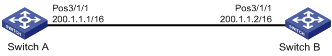
Network requirements
As shown in Figure 4, Switch A and Switch B are connected through their POS 3/1/1 interfaces. Configure Switch A to authenticate Switch B by using PAP, but Switch B not to authenticate Switch A.
Configuration procedure
1. Configure Switch A.
# Create a user account for Switch B.
<SwitchA> system-view
[SwitchA] local-user userb
# Set a password for the user account.
[SwitchA-luser-userb] password simple passb
# Set the service type of the user account to PPP.
[SwitchA-luser-userb] service-type ppp
[SwitchA-luser-userb] quit
[SwitchA] interface Pos 3/1/1
# Enable PPP encapsulation for POS 3/1/1.
[SwitchA-Pos3/1/1] link-protocol ppp
# Set the authentication mode to PAP.
[SwitchA-Pos3/1/1] ppp authentication-mode pap domain system
# Assign an IP address to POS 3/1/1.
[SwitchA-Pos3/1/1] ip address 200.1.1.1 16
[SwitchA-Pos3/1/1] quit
# Configure local authentication for the PPP users in the default ISP domain system.
[SwitchA] domain system
[SwitchA-isp-system] authentication ppp local
2. Configure Switch B.
# Enable PPP encapsulation for POS 3/1/1.
<SwitchB> system-view
[SwitchB] interface Pos 3/1/1
[SwitchB-Pos3/1/1] link-protocol ppp
# Configure the PAP username and password sent from Switch B to Switch A when Switch B is authenticated by Switch A by using PAP.
[SwitchB-Pos3/1/1] ppp pap local-user userb password simple passb
# Assign an IP address to POS 3/1/1 of Switch B.
[SwitchB-Pos3/1/1] ip address 200.1.1.2 16
3. Verify the configurations.
Use the display interface command to display information about POS 3/1/1. The physical layer status and link layer status of the interface are both up, and the states of LCP and IPCP are both Opened, indicating that PPP negotiation is successful. Switch A and Switch B can ping each other.
Two-way PAP authentication configuration example
Network requirements
As shown in 错误!未找到引用源。, Switch A and Switch B are connected through their POS 3/1/1 interfaces. Configure Switch A and Switch B to authenticate each other.
Configuration procedure
1. Configure Switch A.
# Create a user account for Switch B.
<SwitchA> system-view
[SwitchA] local-user userb
# Set a password for the user account.
[SwitchA-luser-userb] password simple passb
# Set the service type of the user account to PPP.
[SwitchA-luser-userb] service-type ppp
[SwitchA-luser-userb] quit
[SwitchA] interface Pos 3/1/1
# Enable PPP encapsulation for POS 3/1/1.
[SwitchA-Pos3/1/1] link-protocol ppp
# Set the authentication mode to PAP.
[SwitchA-Pos3/1/1] ppp authentication-mode pap domain system
# Configure the PAP username and password sent from Switch A to Switch B when Switch A is authenticated by Switch B by using PAP.
[SwitchA-Pos3/1/1] ppp pap local-user usera password simple passa
# Assign an IP address to POS 3/1/1 of Switch A.
[SwitchA-Pos3/1/1] ip address 200.1.1.1 16
[SwitchA-Pos3/1/1] quit
# Configure local authentication for the PPP users in the default ISP domain system.
[SwitchA] domain system
[SwitchA-isp-system] authentication ppp local
2. Configure Switch B.
# Create a user account for Switch A on Switch B.
<SwitchB> system-view
[SwitchB] local-user usera
# Set a password for the user account.
[SwitchB-luser-usera] password simple passa
# Set the service type of the user account to PPP.
[SwitchB-luser-usera] service-type ppp
[SwitchB-luser-usera] quit
[SwitchB] interface Pos 3/1/1
# Enable PPP encapsulation for POS 3/1/1.
[SwitchB-Pos3/1/1] link-protocol ppp
# Set the authentication mode to PAP.
[SwitchB-Pos3/1/1] ppp authentication-mode pap domain system
# Configure the PAP username and password sent from Switch B to Switch A when Switch B is authenticated by Switch A by using PAP.
[SwitchB-Pos3/1/1] ppp pap local-user userb password simple passb
# Assign an IP address to POS 3/1/1.
[SwitchB-Pos3/1/1] ip address 200.1.1.2 16
[SwitchB-Pos3/1/1] quit
# Configure local authentication for the PPP users in the default ISP domain system.
[SwitchB] domain system
[SwitchB-isp-system] authentication ppp local
3. Verify the configurations.
Use the display interface command to display information about POS 3/1/1. The physical layer status and link layer status of the interface are both up, and the states of LCP and IPCP are both Opened, indicating that PPP negotiation is successful. Switch A and Switch B can ping each other.
One-way CHAP authentication configuration example
Network requirements
As shown in 错误!未找到引用源。, use CHAP to authenticate Switch B on Switch A.
Configuration procedure
Approach I: The authenticator configured with a username authenticates the remote end by using CHAP
1. Configure Switch A.
# Create a user account for Switch B.
<SwitchA> system-view
[SwitchA] local-user userb
# Set a password for the user account.
[SwitchA-luser-userb] password simple hello
# Set the service type of the user account to PPP.
[SwitchA-luser-userb] service-type ppp
[SwitchA-luser-userb] quit
[SwitchA] interface Pos 3/1/1
# Enable PPP encapsulation for POS 3/1/1.
[SwitchA-Pos3/1/1] link-protocol ppp
# Configure the username for Switch A when Switch A authenticates Switch B.
[SwitchA-Pos3/1/1] ppp chap user usera
# Set the authentication mode to CHAP.
[SwitchA-Pos3/1/1] ppp authentication-mode chap domain system
# Assign an IP address to POS 3/1/1
[SwitchA-Pos3/1/1] ip address 200.1.1.1 16
[SwitchA-Pos3/1/1] quit
# Configure local authentication for the PPP users in the default ISP domain system.
[SwitchA] domain system
[SwitchA-isp-system] authentication ppp local
2. Configure Switch B.
# Create a user account for Switch A on Switch B.
<SwitchB> system-view
[SwitchB] local-user usera
# Set a password for the user account.
[SwitchB-luser-usera] password simple hello
# Set the service type of the user account to PPP.
[SwitchB-luser-usera] service-type ppp
[SwitchB-luser-usera] quit
[SwitchB] interface Pos 3/1/1
# Enable PPP encapsulation for POS 3/1/1.
[SwitchB-Pos3/1/1] link-protocol ppp
# Configure the username for Switch B when Switch B is authenticated.
[SwitchB-Pos3/1/1] ppp chap user userb
# Assign an IP address to POS 3/1/1 of Switch B.
[SwitchB-Pos3/1/1] ip address 200.1.1.2 16
Approach II: The authenticator with no username configured authenticates the remote end by using CHAP.
1. Configure Switch A.
# Create a user account for Switch B.
<SwitchA> system-view
[SwitchA] local-user userb
# Set a password for the user account.
[SwitchA-luser-userb] password simple hello
# Set the service type of the user account to PPP.
[SwitchA-luser-userb] service-type ppp
[SwitchA-luser-userb] quit
[SwitchA] interface Pos 3/1/1
# Set the authentication mode to CHAP.
[SwitchA-Pos3/1/1] ppp authentication-mode chap domain system
# Assign an IP address to POS 3/1/1.
[SwitchA-Pos3/1/1] ip address 200.1.1.1 16
[SwitchA-Pos3/1/1] quit
# Configure local authentication for the PPP users in the default ISP domain system.
[SwitchA] domain system
[SwitchA-isp-system] authentication ppp local
2. Configure Switch B.
# Configure the username of Switch B when Switch B is authenticated.
<SwitchB> system-view
[SwitchB] interface Pos 3/1/1
[SwitchB-Pos3/1/1] ppp chap user userb
# Set the default CHAP password.
[SwitchB-Pos3/1/1] ppp chap password simple hello
# Assign an IP address to POS 3/1/1.
[SwitchB-Pos3/1/1] ip address 200.1.1.2 16
3. Verify the configurations.
Use the display interface command to display information about POS 3/1/1. The physical layer status and link layer status of the interface are both up, and the states of LCP and IPCP are both Opened, indicating that PPP negotiation is successful. Switch A and Switch B can ping each other.
Troubleshooting PPP configuration
A link cannot revert to the up state
Symptom
PPP authentication always fails, preventing the link from going up.
Solution
This problem may occur if the authentication parameter settings are incorrect.
· Enable the debugging of PPP, and you can see the information describing that LCP went up upon a successful LCP negotiation but went down after PAP or CHAP negotiation.
· Check the PPP authentication settings at the local and peer ends to make sure that they are consistent.
A physical link remains down
Symptom
A physical link remains down.
Solution
Check the following items:
· The interface has been brought up.
· The interface is not administratively down.
· LCP negotiation has passed.
Execute the display interface serial command to check the state of the interface. The output information can be:
· Pos3/1/1 current state: DOWN (Administratively), Line protocol current state: DOWN, which indicates that the interface is shut down by the administrator.
· Pos3/1/1 current state: DOWN, Line protocol current state: DOWN, which indicates that the interface is not activated or the physical layer has not gone up yet.
· Pos3/1/1 current state: UP, Line protocol current state: UP, which indicates that LCP negotiation succeeded.
· Pos3/1/1 current state: UP, Line protocol current state: DOWN, which indicates that the interface is activated, but LCP negotiation failed.
A link remains down after IPv6CP negotiation fails
Symptom
Configure an IPv6 address on a PPP-encapsulated interface when IPv6 is disabled. The PPP link fails IPv6CP negotiation and cannot go up. After IPv6 is enabled, the interface still cannot go up.
Analysis
IPv6CP negotiation cannot succeed when IPv6 is disabled. As IPv6CP does not support re-negotiation, IPv6CP negotiation cannot succeed even if you enable IPv6 later.
Solution
To resolve the problem, do the following:
· Enable IPv6 before configuring an IPv6 address on a PPP link.
· If IPv6CP negotiation fails, shut down and then bring up the interface by using the shutdown and undo shutdown commands to re-enable IPv6CP negotiation.