- Table of Contents
-
- 01-Fundamentals Configuration Guide
- 00-Preface
- 01-CLI Configuration
- 02-Login Management Configuration
- 03-FTP and TFTP Configuration
- 04-File System Management
- 05-Configuration File Management Configuration
- 06-Software Upgrade Configuration
- 07-ISSU Configuration
- 08-Device Management Configuration
- 09-Automatic Configuration
- Related Documents
-
| Title | Size | Download |
|---|---|---|
| 02-Login Management Configuration | 1020.62 KB |
Contents
Logging in through the console or AUX port
Logging in to the switch from a Telnet client
Telnetting from the switch to another device
Logging in to the switch from an SSH client
Configuring the SSH client to log in to the SSH server
Logging in through the AUX port by using modems
Configurations on the administrator side
Setting up a configuration environment
Logging in to the web interface
Configuring source IP-based login control over web users
Configuring source IP-based login control over web users
Source IP-based login control over web users configuration example
Displaying and maintaining web login
Logging in through SNMP from an NMS
Logging in through CWMP from an ACS
User interface configuration task list
Configuring user interface attributes
Configuring asynchronous serial interface attributes
Configuring common settings for user interfaces
Configuring a command to be automatically executed
Configuring user privilege level under a user interface
Configuring access control on VTY user interfaces
Configuring supported protocols on VTY user interfaces
Configuring authentication mode
Configuring command authorization
Configuring command accounting
Defining shortcut keys for starting terminal sessions/aborting tasks
Sending messages to the specified user interfaces
Releasing the connection established on the user interfaces
Displaying and maintaining user interfaces
User interface configuration examples
User authentication configuration example
Command authorization configuration example
Command accounting configuration example
Configuring login control over Telnet users
Configuring source IP-based login control over Telnet users
Configuring source and destination IP-based login control over Telnet users
Configuring source MAC-based login control over Telnet users
Source MAC-based login control configuration example
Login methods
You can enter the command-line interface (CLI) of your switch in a variety of ways.
Table 1 Login methods
|
Login method |
Default settings |
|
|
By default, you can log in to your switch through the console or AUX port, the authentication mode is None (no username or password required), and the user privilege level is 3. |
||
|
By default, you cannot log in to your switch through Telnet. To do so, log in to your switch through the console port, and complete the following configurations: · Enable the Telnet server function of your switch. By default, the Telnet server function is disabled. · Configure the IP address of the network management port or VLAN interface of your switch, and make sure that your switch and the Telnet client can reach each other (by default, your switch does not have an IP address.). · Configure the authentication mode of VTY login users (password by default). · Configure the user privilege level of VTY login users (0 by default). |
||
|
By default, you cannot log in to your switch through SSH. To do so, log in to your switch through the console port, and complete the following configurations: · Enable the SSH server function of your switch. By default, the SSH server function is disabled. · Configure the IP address of the network management port or VLAN interface of your switch, and make sure that your switch and the SSH client can reach each other (by default, your switch does not have an IP address.). · Configure the authentication mode of VTY login users as scheme (password by default). · Configure the user privilege level of VTY login users (0 by default). |
||
|
By default, you cannot log in to your switch by using modem dial-in through the AUX port. To do so, log in to your switch through the console port, and complete the following configurations: · Configure the authentication mode of AUX login users (password by default). · Configure the user privilege level of AUX login users (0 by default). |
||
Logging in through the console or AUX port
Introduction
|
|
NOTE: The AUX port can be used as the backup of the console port. Using the AUX port for local login is the same as using the console port. The following uses the console port login as an example to describe the configuration and login procedure. |
Logging in through the console port is the most common way to log in to a switch. It is also the prerequisite to configure other login methods. By default, you can log in to the switch through its console port only.
To log in to the switch through its console port, the related configuration of the user terminal must be in accordance with that of the console port.
Table 2 Default settings of the console port
|
Setting |
Default |
|
Baud rate |
9600 bps |
|
Flow control |
Off |
|
Check mode |
No check bit |
|
Stop bits |
1 |
|
Data bits |
8 |
Configuration procedure
1. As shown in Figure 1, use a console cable to connect the serial port of your PC (or terminal) to the console port of your switch.
Figure 1 Setting up a configuration environment
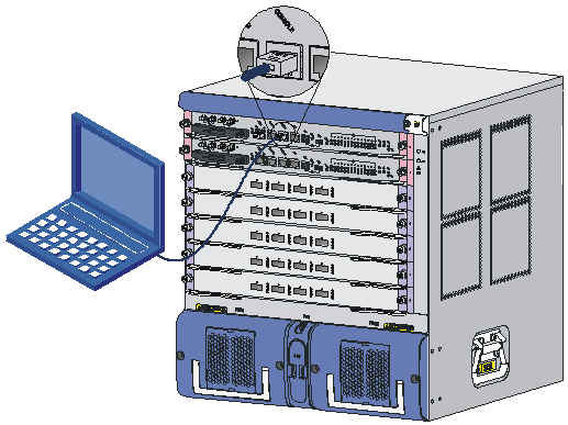
1. Connect the DB-9 connector of the console cable to the serial port of a PC or terminal.
2. Connect the RJ-45 connector of the console cable to the console port of the main board of the switch.
|
|
NOTE: · If two main boards are installed on the switch, log in through the console port on the active main board (AMB) (typically with a smaller slot number) for the first login. · When you remove the console cable, first unplug the RJ-45 end, and then the DB-9 end. |
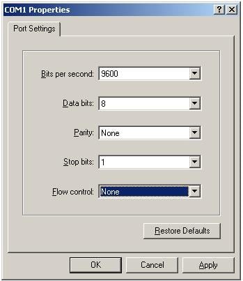
3. Launch a terminal emulation utility (such as HyperTerminal in Windows XP/Windows 2000), select a serial port to be connected to the switch, and set terminal parameters as follows: set Bits per second to 9600, Data bits to 8, Parity to None, Stop bits to 1, and Flow control to None, as shown in Figure 2 through Figure 4.
|
|
NOTE: If you use the Windows 2003 Server operating system on your PC, add a HyperTerminal, and then log in to and manage the switch as described in this document. If you use Windows 2008 Server, Windows 7, Windows Vista, or any other operating system on your PC, use the third party terminal software. For how to use the third party terminal software, see the user guide or online help of that software. |
Figure 2 Connection description
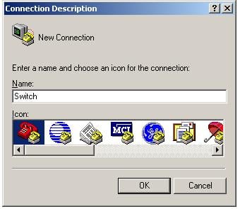
Figure 3 Specifying the serial port used to establish the connection
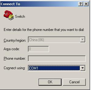
Figure 4 Setting the properties of the serial port
4. Turn on the switch. Press Enter if the switch successfully completes the power-on self test (POST). The following prompt appears when you press Enter:
<Sysname>
5. Execute commands to configure the switch or check the running status of the switch. To get help, enter ?.
After the steps above, you can enter the CLI to configure and manage your switch. By default, users that log in through the console port are not authenticated. For security, you are recommended to change the authentication mode of the console port. The following describes how to configure password authentication.
<Sysname> system-view
[Sysname] user-interface console 0
[Sysname-ui-console0] authentication-mode password
[Sysname-ui-console0] set authentication password cipher 123
After the configuration above, when users log in through the console port, they must enter authentication password 123 to pass authentication and then log in to the switch.
|
|
NOTE: · You can set the authentication mode of console login users to none or scheme (username and password authentication). For more information about authentication modes, see “Configuring authentication mode.” · After you log in through the console port, you can also set login parameters other than the authentication mode. For more information, see “Configuring user interface attributes.” |
Logging in through Telnet
Introduction
You can remotely manage and maintain your switch through Telnet.
To log in to your switch through Telnet, perform necessary configurations on both your switch and the Telnet client.
Table 3 Telnet login requirements
|
Device |
Requirement |
|
Telnet server |
· Configure the IP address of the Telnet server. · Make sure that the Telnet server and client can reach each other. · Enable the Telnet server. · Configure the authentication mode for Telnet login. |
|
Telnet client |
· Run the Telnet program · Obtain the IP address of the Telnet server to log in. |
The switch can either operate as a Telnet server or client.
· As a Telnet server
By default, the switch is disabled with the Telnet server function, and password authentication is adopted for Telnet login, but no login password is configured. Therefore, you cannot log in to the switch through Telnet by default.
To log in to the switch through Telnet, perform the following configuration first:
a. Log in to your switch through the console port, and configure the IP address of the network management interface or VLAN interface of the switch.
b. Enable the Telnet server function with the telnet server enable command.
c. Specify an authentication mode for Telnet login.
d. Configure user privilege level and common settings (optional). For more information, see “Configuring common settings for user interfaces.”
· As a Telnet client
By default, the switch is enabled with the Telnet client function, and you can log in to a Telnet server from the switch to perform operations on the server.
Logging in to the switch from a Telnet client
|
|
NOTE: This section uses a PC as the Telnet client. |
1. Log in to the switch through the console port, and configure the IP address of the network management port of the switch. For more information about how to log in to the switch through the console port, see “Logging in through the console or AUX port.”
|
|
IMPORTANT: You can Telnet to your switch through the network management port or any other Layer 3 interface (for example, Layer 3 Ethernet interfaces and VLAN interfaces). |
# Configure the IP address of the network management port as 202.38.160.92/24.
<Sysname> system-view
[Sysname] interface M-Ethernet 0/0/0
[Sysname-M-Ethernet0/0/0] ip address 202.38.160.92 255.255.255.0
2. Enable the Telnet server function of the switch.
|
Step |
Command |
Remarks |
|
1. Enter system view. |
system-view |
N/A |
|
2. Enable the Telnet server. |
telnet server enable |
Disabled by default. |
3. Enter VTY user interface view, and configure the authentication mode as needed. For more information, see “Configuring authentication mode.”
4. Configure the user privilege level. Users that telnet to the switch can only execute level 0 commands by default. For more information about command levels, see “Configuring user privilege level under a user interface.”
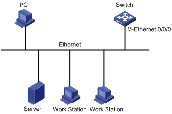
5. Set up a configuration environment as shown in Figure 5: Connect the Ethernet port of your PC to the network management port of your switch, and make sure that the PC and switch can reach each other.
Figure 5 Setting up a configuration environment
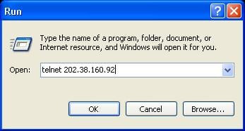
6. Telnet to the IP address of the management port of the switch, as shown in Figure 6.
Figure 6 Running the Telnet program
7. If the authentication mode is none, you can log in to the switch without any authentication. If the authentication mode is password, the terminal prompts you to enter the login password. If the authentication mode is scheme, you must enter the username and password to log in to the switch. After you enter the correct username and password, if the switch prompts you to enter another password of the specified type, you will be authenticated for the second time. In other words, to pass authentication, you must enter a correct password as prompted.
8. Execute commands to configure the switch, or check the running status of the switch. To get help, enter ?.
|
|
NOTE: · When configuring your switch through Telnet, do not delete or change the IP address of the network management port or VLAN interface corresponding to the Telnet connection. Otherwise, the Telnet connection will be terminated. · “All user interfaces are used, please try later!” means the number of concurrent Telnet login users exceed the upper limit. Please try later. |
Telnetting from the switch to another device
To telnet to another device from the local switch, follow these steps:
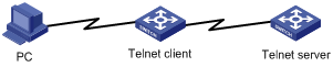
1. Set up a configuration environment as shown in Figure 7.
Figure 7 Telnetting from the switch (Telnet client) to another device (Telnet server)
|
|
NOTE: If the two switches are not in the same LAN, make sure that the two switches can reach each other. |
2. Configure the Telnet server.
a. Enable the Telnet server.
b. Configure the authentication mode on the Telnet server as needed.
3. Log in to the switch that operates as the Telnet client.
4. Execute the telnet command on the Telnet client to log in to the Telnet server:
|
Step |
Command |
Remarks |
|
1. Enter system view. |
system-view |
N/A |
|
2. Specify the source IPv4 address or source interface for sending Telnet packets when the switch serves as a Telnet client. |
telnet client source { interface interface-type interface-number | ip ip-address } |
Optional. By default, no source IPv4 address or source interface for sending Telnet packets is specified. The source IPv4 address is selected by routing. |
|
3. Exit to user view. |
quit |
N/A |
|
4. Telnet to the Telnet server. |
· telnet remote-host [ service-port ] [ [ vpn-instance vpn-instance-name ] | [ source { interface interface-type interface-number | ip ip-address } ] ] · telnet ipv6 remote-host [ -i interface-type interface-number ] [ port-number ] [ vpn-instance vpn-instance-name ] |
Use either approach. Available in user view. |
5. After login, a prompt appears (for example, <Sysname> ). If “All user interfaces are used, please try later!” appears, try again later.
6. Execute commands to configure the switch, or check the running status of the switch. To get help, enter ?.
Logging in through SSH
Introduction
Secure Shell (SSH) offers an approach to log in to a remote device securely. By providing encryption and strong authentication, it protects devices against attacks such as IP spoofing and plain text password interception. The switch supports SSH, and you can log in to the switch through SSH to remotely manage and maintain the switch, as shown in Figure 8.
The following table shows the configuration requirements of SSH login:
|
Object |
Requirements |
|
SSH server |
· Configure the IP address of the SSH server, and make sure the SSH server and client can reach each other. · Configure the authentication mode and other settings. |
|
SSH client |
· If the host operates as an SSH client, run the SSH client program on the host. · Obtain the IP address of the SSH server. |
The switch can operate as either an SSH server or client.
As an SSH server:
· You can perform configurations on the SSH server to control SSH client login.
· By default, the switch is disabled with the SSH server function. Therefore, before you can log in to the switch through SSH, you need to log in to the switch through the console port and configure the authentication mode, user level, and common settings.
As an SSH client:
· You can log in to an SSH sever from the client to perform operations on the server.
· By default, the switch is enabled with the SSH client function.
Logging in to the switch from an SSH client
Configuration prerequisites
Log in to the switch through the console port. For more information, see “Logging in through the console or AUX port.”
Configuration procedure
To configure the switch that serves as an SSH server:
|
Step |
Command |
Remarks |
|
1. Enter system view. |
system-view |
N/A |
|
2. Create local key pair(s). |
public-key local create { dsa | rsa } |
By default, no local key pair(s) are created. |
|
3. Enable SSH server. |
ssh server enable |
By default, SSH server is disabled. |
|
4. Exit to system view. |
quit |
N/A |
|
5. Enter one or more VTY user interface views. |
user-interface vty first-number [ last-number ] |
N/A |
|
6. Specify the scheme authentication mode. |
authentication-mode scheme |
By default, authentication mode for VTY user interfaces is password. |
|
7. Enable the current user interface to support either Telnet, SSH, or both of them. |
protocol inbound { all | ssh } |
Optional. By default, both protocols are supported. |
|
8. Exit to system view. |
quit |
N/A |
|
9. Configure the authentication mode. |
1.
Enter the default ISP domain view: 2.
Apply the specified AAA scheme to the domain: 3.
Exit to system view: |
Optional. By default, the AAA scheme is local. If you specify the local AAA scheme, perform the configuration concerning local user as well. If you specify an existing scheme by providing the radius-scheme-name argument, perform the following configuration as well: · For RADIUS and HWTACACS configuration, see Security Configuration Guide. · Configure the username and password on the AAA server. (For more information, see Security Configuration Guide.) |
|
10. Create a local user and enter local user view. |
local-user user-name |
By default, no local user exists. |
|
11. Set the local password. |
password { cipher | simple } password |
By default, no local password is set. |
|
12. Specify the command level of the local user. |
authorization-attribute level level |
Optional. By default, the command level is 0. |
|
13. Specify the service type for the local user. |
service-type ssh |
By default, no service type is specified. |
|
14. Return to system view. |
quit |
N/A |
|
15. Create an SSH user, and specify the authentication mode for the SSH user. |
ssh user username service-type stelnet authentication-type { password | { any | password-publickey | publickey } assign publickey keyname } |
Optional. By default, no SSH user exists, and no authentication mode is specified. |
|
16. Configure common settings for VTY user interfaces. |
N/A |
Optional. |
|
|
NOTE: This chapter describes how to configure an SSH client by using password authentication. For more information about SSH and how to configure an SSH client by using publickey, see Security Configuration Guide. |
After you enable command authorization or command accounting, you need to perform the following configuration to make the function take effect:
· Create an HWTACACS scheme, and specify the IP address of the authorization server and other authorization parameters.
· Reference the created HWTACACS scheme in the ISP domain.
For more information, see Security Configuration Guide.
When users adopt the scheme mode to log in to the switch, the level of the commands that the users can access depends on the user privilege level defined in the AAA scheme:
· When the AAA scheme is local, the user privilege level is defined by the authorization-attribute level level command.
· When the AAA scheme is RADIUS or HWTACACS, the user privilege level is configured on the RADIUS or HWTACACS server.
For more information about AAA, RADIUS, and HWTACACS, see Security Configuration Guide.
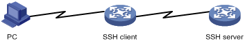
Configuring the SSH client to log in to the SSH server
Configuration prerequisites
Log in to the switch through the console port. For more information, see “Logging in through the console or AUX port.”
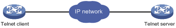
Figure 9 Logging in to another device from the current device
|
|
NOTE: If the Telnet client and the Telnet server are not in the same subnet, make sure that the two devices can reach each other. |
Configuration procedure
To configure the SSH client to log in to the SSH server:
|
Task |
Command |
Remarks |
|
Log in to an IPv4 SSH server. |
ssh2 server [ port-number ] [ vpn-instance vpn-instance-name ] [ identity-key { dsa | rsa } | prefer-ctos-cipher { 3des | aes128 | des } | prefer-ctos-hmac { md5 | md5-96 | sha1 | sha1-96 } | prefer-kex { dh-group-exchange | dh-group1 | dh-group14 } | prefer-stoc-cipher { 3des | aes128 | des } | prefer-stoc-hmac { md5 | md5-96 | sha1 | sha1-96 } ] * |
server is the IPv4 address or host name of the server. Available in user view. |
|
Log in to an IPv6 SSH server. |
ssh2 ipv6 server [ port-number ] [ vpn-instance vpn-instance-name ] [ identity-key { dsa | rsa } | prefer-ctos-cipher { 3des | aes128 | des } | prefer-ctos-hmac { md5 | md5-96 | sha1 | sha1-96 } | prefer-kex { dh-group-exchange | dh-group1 | dh-group14 } | prefer-stoc-cipher { 3des | aes128 | des } | prefer-stoc-hmac { md5 | md5-96 | sha1 | sha1-96 } ] * |
server is the IPv6 address or host name of the server. Available in user view. |
|
|
NOTE: You can configure other settings for the switch (SSH client) to work with the SSH server. For more information, see Security Configuration Guide. |
Logging in through the AUX port by using modems
Introduction
An administrator can use two modems and the Public Switched Telephone Network (PSTN) to remotely maintain a remote switch through its AUX port. When the network connection is broken, you can use this method to remotely configure a switch, query logs and alarms, and locate faults over the PSTN.
To use this method, perform necessary configurations at both the switch side and administrator side.
Table 4 Requirements of remote login through AUX port by using modem dial-in
|
Device |
Requirement |
|
Administrator side |
· The PC is correctly connected to the modem. · The modem is connected to a telephone cable that works normally. · The telephone number of the remote modem connected to the AUX port of the remote switch is obtained. |
|
Switch side |
· The AUX port is correctly connected to the modem. · Configurations have been configured on the modem. · The modem is connected to a telephone cable that works normally. · Authentication configuration has been completed on the remote switch. For more information, see “Configuring authentication mode.” |
Configurations on the administrator side
The PC and the modem are correctly connected, the modem is connected to a telephone cable that works normally, and the telephone number of the remote modem connected to the AUX port of the remote switch is obtained.
Configurations on the switch
Configuration on the modem that is directly connected to the switch
Perform the following configurations on the modem that is directly connected to the switch (no configuration is needed on the modem connected to the terminal):
AT&F ----------------------- Restore the factory defaults
ATS0=1 ----------------------- Configure auto-answer on first ring
AT&D ----------------------- Ignore data Terminal Ready signals
AT&K0 ----------------------- Disable local flow control
AT&R1 ----------------------- Ignore Data Flow Control signals
AT&S0 ----------------------- Force DSR to remain on
ATEQ1&W ----------------------- Disable the modem from response to commands and save the configuration
To verify your configuration, enter AT&V to show the configuration results.
|
|
NOTE: The configuration commands and the output for different modems may be different. For more information, see the user guide of your modem. |
Configuration on the switch
When configuring the switch, note the following guidelines:
· The transmission speed on the AUX port must be lower than that of the modem. Otherwise, packets may be lost.
· Other attributes (parity check, stop bits, and data bits) of the AUX port adopt the default values.
Setting up a configuration environment
1. Perform the following configurations on the modem that is directly connected to your switch:
AT&F ----------------------- Restore the factory defaults
ATS0=1 ----------------------- Configure auto-answer on first ring
AT&D ----------------------- Ignore data Terminal Ready signals
AT&K0 ----------------------- Disable local flow control
AT&R1 ----------------------- Ignore Data Flow Control signals
AT&S0 ----------------------- Force DSR to remain on
ATEQ1&W ----------------------- Disable the modem from response to commands and save the configuration
To verify your configuration, execute the AT&V command to display the configuration results.
2. Set up a configuration environment as shown in Figure 10: connect the serial port of the PC and the AUX port of the switch to a modem respectively.
Figure 10 Setting up a configuration environment

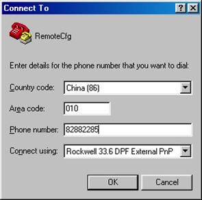
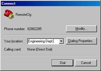
3. Dial the destination number (the number of the modem that is connected to the switch) on the PC to establish a connection with the switch, as shown in Figure 11 through Figure 13.
Figure 11 Connection Description
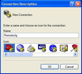
Figure 12 Entering the phone number
4. If the authentication mode is password, a prompt (for example, Sysname) appears after you enter the configured password. Then you can configure or manage the switch. To get help, enter ?.
Logging in to the web interface
Overview
The switch provides a built-in web server. It enables you to log in to the web interface of the switch from a PC. Web login is disabled by default.
To enable web login, log in to the switch via the console port, and perform the following configuration:
· Enable HTTP service
· Configure the IP address of the VLAN interface
· Configure a username and password
The switch supports logging in to the web interface through the Hypertext Transfer Protocol (HTTP). HTTP is used for transferring web page information across the Internet. It is an application-layer protocol in the TCP/IP protocol suite. The connection-oriented Transport Control Protocol (TCP) is adopted at the transport layer. Currently, the switch supports HTTP 1.0.
The following table shows the configuration requirements of web login:
|
Object |
Requirements |
|
Device |
· Configuring the IP address of the VLAN interface. Making sure the switch and the PC can reach each other. |
|
PC |
· Installing a web browser. · Obtaining the IP address of the VLAN interface of the switch. |
Configuring HTTP login
To configure HTTP login:
|
Step |
Command |
Remarks |
|
1. Specify a fixed verification code for web login. |
web captcha verification-code |
Optional. By default, a web user must enter the verification code indicated on the login page to log in. This command is available in user view. |
|
2. Enter system view. |
system-view |
N/A |
|
3. Enable the HTTP service. |
ip http enable |
Enabled by default. |
|
4. Configure the HTTP service port number. |
ip http port port-number |
Optional. 80 by default. If you execute the command multiple times, the last one takes effect. |
|
5. Associate the HTTP service with an ACL. |
ip http acl acl-number |
Optional. By default, the HTTP service is not associated with any ACL. Associating the HTTP service with an ACL enables the switch to allow only clients permitted by the ACL to access the switch. |
|
6. Create a local user and enter local user view. |
local-user user-name |
By default, no local user is configured. |
|
7. Configure a password for the local user. |
password { cipher | simple } password |
By default, no password is configured for the local user. |
|
8. Specify the command level of the local user. |
authorization-attribute level level |
No command level is configured for the local user. |
|
9. Specify the Telnet service type for the local user. |
service-type web |
By default, no service type is configured for the local user. |
|
10. Exit to system view. |
quit |
N/A |
|
11. Create a VLAN interface and enter its view. |
interface vlan-interface vlan-interface-id |
If the VLAN interface already exists, the command enters its view. |
|
12. Assign an IP address and subnet mask to the VLAN interface. |
ip address ip-address { mask | mask-length } |
By default, no IP address is assigned to the VLAN interface. |
Configuring source IP-based login control over web users
You can log in to the web management page of the switch through HTTP to remotely manage the switch. By using the ACL, you can control web user access to the switch.
Configuration preparation
Before configuration, determine the permitted or denied source IP addresses.
Configuring source IP-based login control over web users
Basic ACLs match the source IP addresses of packets, so you can use basic ACLs to implement source IP-based login control over web users. Basic ACLs are numbered from 2000 to 2999. For more information about ACL, see ACL and QoS Configuration Guide.
To configure source IP-based login control over web users:
|
Step |
Command |
Remarks |
|
1. Enter system view. |
system-view |
N/A |
|
2. Create a basic ACL and enter its view, or enter the view of an existing basic ACL. |
acl [ ipv6 ] number acl-number [ match-order { config | auto } ] |
By default, no basic ACL exists. |
|
3. Create rules for this ACL. |
rule [ rule-id ] { permit | deny } [ source { sour-addr sour-wildcard | any } | time-range time-name | fragment | logging ]* |
N/A |
|
Exit the basic ACL view. |
quit |
N/A |
|
5. Associate the HTTP service with the ACL. |
ip http acl acl-number |
N/A |
Logging off online web users
To log off online web users:
|
Task |
Command |
Remarks |
|
Log off online web users. |
free web-users { all | user-id user-id | user-name user-name } |
Available in user interface view |
Source IP-based login control over web users configuration example
Network requirements
As shown in Figure 14, configure the switch to allow only web users from Host B to access.
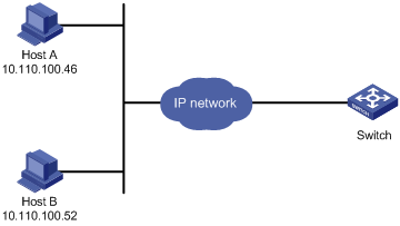
Configuration procedure
# Create ACL 2000, and configure rule 1 to permit packets sourced from Host B.
<Sysname> system-view
[Sysname] acl number 2030 match-order config
[Sysname-acl-basic-2030] rule 1 permit source 10.110.100.52 0
# Associate the ACL with the HTTP service so that only web users from Host B are allowed to access the switch.
[Sysname] ip http acl 2030
Displaying and maintaining web login
|
Task |
Command |
Remarks |
|
Display information about web users. |
display web users [ | { begin | exclude | include } regular-expression ] |
Available in any view |
|
Display HTTP state information. |
display ip http [ | { begin | exclude | include } regular-expression ] |
Available in any view |
Web login example
Network requirements
As shown in Figure 15, configure the switch to allow the PC to log in over the IP network.
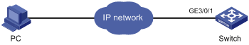
Configuration procedure
1. Configure the switch
# Create VLAN 999 and add interface GigabitEthernet 3/0/1 that connects the switch to the PC to the VLAN.
<Sysname> system-view
[Sysname] vlan 999
[Sysname-vlan999] port GigabitEthernet 3/0/1
[Sysname-vlan999] quit
# Specify the IP address and subnet mask of VLAN-interface 999 as 192.168.0.58 and 255.255.255.0.
[Sysname] interface vlan-interface 999
[Sysname-VLAN-interface999] ip address 192.168.0.58 255.255.255.0
[Sysname-VLAN-interface999] quit
# Create a local user named admin, and set the password to admin for the user. Specify the Telnet service type for the local user, and set the command level to 3 for this user.
[Sysname] local-user admin
[Sysname-luser-admin] service-type web
[Sysname-luser-admin] authorization-attribute level 3
[Sysname-luser-admin] password simple admin
2. Verify the configuration
# On the PC, run the web browser. Enter the IP address of the switch in the address bar. The web login page appears, as shown in Figure 16.
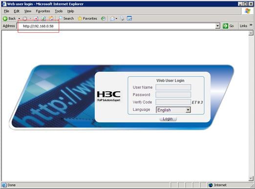
# Enter the user name, password, verify code, select English, and click Login. The homepage appears. After login, you can configure switch settings through the web interface.
Overview
A network management system (NMS) runs the SNMP client software. It offers a user-friendly interface to facilitate network management. An agent is a program that resides in the switch. It receives and handles requests from the NMS. An NMS is a manager in an SNMP enabled network, whereas agents are managed by the NMS. The NMS and agents exchange information through the SNMP protocol. The switch supports multiple NMS programs, such as iMC.
By default, you cannot log in to the switch through NMS. To enable NMS login, log in to the switch through the console port and make the configurations described in the following table.
The following table shows the requirements for NMS login:
|
Object |
Requirements |
|
Switch |
· Assign an IP address to a Layer 3 interface. Make sure the switch and the NMS can reach each other. Configure SNMP settings. |
|
NMS |
Configure the NMS. For more information, see the manual of your NMS. |
|
|
NOTE: The switch supports connecting to a NMS through the network management interface, a VLAN interface, a Layer 3 Ethernet interface, or a Layer 3 Ethernet subinterface. |
Configuring SNMP agent
Before configuring SNMP on the switch, connect the Ethernet port of the NMS host to an Ethernet port of VLAN 1 on the switch, and make sure that the NMS host and VLAN 1 interface can reach each other.
|
|
NOTE: The switch supports three SNMP versions: SNMPv1, SNMPv2c, and SNMPv3. For more information about SNMP, see Network Management and Monitoring Configuration Guide. |
To configure SNMPv3 agent:
|
Step |
Command |
Remarks |
|
1. Enter system view. |
system-view |
N/A |
|
2. Enable SNMP agent. |
snmp-agent |
Optional. Disabled by default. You can enable SNMP agent with this command or any command that begins with snmp-agent. |
|
3. Configure an SNMP group and specify its access right. |
snmp-agent group v3 group-name [ authentication | privacy ] [ read-view read-view ] [ write-view write-view ] [ notify-view notify-view ] [ acl acl-number ] |
By default, no SNMP group is configured. |
|
4. Add a user to the SNMP group. |
snmp-agent usm-user v3 user-name group-name [ [ cipher ] authentication-mode { md5 | sha } auth-password [ privacy-mode { 3des | aes128 | des56 } priv-password ] ] [ acl acl-number ] |
If the cipher keyword is specified, both auth-password and priv-password are cipher text passwords. |
To configure SNMPv1 or SNMPv2c agent:
|
Step |
Command |
Remarks |
|
1. Enter system view. |
system-view |
N/A |
|
2. Enable SNMP agent. |
snmp-agent |
Optional. Disabled by default. You can enable SNMP agent with this command or any command that begins with snmp-agent. |
|
3. Create or update MIB view information. |
snmp-agent mib-view { excluded | included } view-name oid-tree [ mask mask-value ] |
Optional. By default, the MIB view name is ViewDefault and OID is 1. |
|
4. Specify the SNMP NMS access right. |
·
(Approach 1) Specify the SNMP NMS access right
directly by configuring an SNMP community · (Approach 2) Specify the SNMP NMS access right indirectly a. Configure an SNMP group b. Add a user to the SNMP group |
Use either approach. The direct configuration approach is for SNMPv1 or SNMPv2c. The community name configured on the NMS should be consistent with the username configured on the agent. The indirect configuration approach is for SNMPv3. |
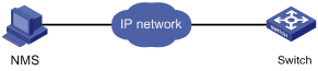
NMS login example
In this example, iMC is used as the NMS for illustration.
1. Configure the switch
# Assign IP address 13.13.13.111/24 to VLAN-interface 1. Make sure the switch and the NMS host can reach each other. (Details not shown)
# Enter system view.
<Sysname> system-view
# Enable the SNMP agent.
[Sysname] snmp-agent
# Create an SNMP community and assign access rights.
[Sysname] snmp-agent sys-info version all
[Sysname] snmp-agent community read public
[Sysname] snmp-agent community write private
# Configure an SNMP group.
[Sysname] snmp-agent group v3 managev3group
# Add a user to the SNMP group.
[Sysname] snmp-agent usm-user v3 managev3user managev3group
2. Configure the iMC system
a. On the PC, launch a browser, and enter http://192.168.4.112:8080/imc in the address bar (suppose that the IP address of the iMC is 192.168.4.112).
b. On the login page, enter the username and password, and then click Login.
The iMC homepage appears.
c. Configure the switch in the iMC system. (Details not shown)
For more information about iMC, see the manuals for iMC.
|
|
NOTE: · The settings of the switch in the iMC system must match those of the switch. For more information about NMS and SNMP agent configuration on the iMC and switch, see Network Management and Monitoring Configuration Guide. · When you log in to the iMC system for the first time, you can use the default account with the username admin and password admin. Be sure to change the password immediately after login. For how to change the password, see the manuals for iMC, such as H3C Intelligent Management Center Getting Started Guide. · You can also add accounts with different rights for operators and perform other operations in the iMC system. For more information, see the online help of iMC. |
You can launch a browser on a PC to log in to an auto-configuration server (ACS), and use the server to access and manage customer premises equipment (CPE) through the CPE WAN Management Protocol (CWMP).
CWMP is intended for management and configuration of home network devices in DSL access networks. The H3C implementation of the ACS system is the iMC branch intelligent management system (BIMS) component, which runs on the iMC platform.
To log in to an ACS running BIMS from a PC, follow these steps:
1. Launch a browser on the PC.
2. Enter http:// 0.185.10.41:8080/imc in the address bar (suppose that the ACS uses the IP address 10.185.10.41 and the port 8080).
3. Enter the login username and password, which are the same as those used for logging in to iMC.
|
|
NOTE: · When you log in to the iMC system for the first time, you can use the default account with the username admin and password admin. Be sure to change the password immediately after login. For how to change the password, see the manuals for iMC, such as H3C Intelligent Management Center Getting Started Guide. · You can also add accounts with different rights for operators and perform other operations in the iMC system. For more information, see the online help of iMC. · For more information about ACS, see Network Management and Monitoring Configuration Guide. · For more information about iMC BIMS, see the manuals for iMC BIMS. |
Overview
A user interface (also called a line) allows you to manage and monitor sessions between the terminal and switch when you are using the console port, AUX port, and asynchronous serial interfaces to log in to the switch by Telnet or SSH.
Asynchronous serial interfaces include the following two types:
· Synchronous/asynchronous serial interface operating in asynchronous mode, whose interface index begins with Serial.
· Dedicated asynchronous serial interface, whose interface index begins with Async.
One user interface corresponds to one user interface view where you can configure a set of parameters, such as whether to authenticate users at login, whether to redirect the requests to another device, and the user level after login. When the user logs in through a user interface, the connection follows these parameter settings, thus implementing centralized management of various sessions.
At present, the system supports the following CLI configuration modes:
· Local configuration via the console port
· Local/Remote configuration via the AUX port (Auxiliary port)
· Local/Remote configuration via the asynchronous serial port
· Local/Remote configuration through Telnet or SSH
The four modes correspond to three types of user interfaces. They are:
· Console user interface—Manages and monitors users that log in via the console port. Console port is a line device port. The switch provides console ports of EIA/TIA-232 DCE type.
· AUX user interface—Manages and monitors users that log in via the AUX port. AUX port is also a line device port. The switch provides AUX ports of EIA/TIA-232 DTE type. The port is usually used for dialup access via modem.
· VTY (virtual type terminal) user interface—Manages and monitors users logging in via VTY. VTY port is a logical terminal line used when you access the switch through Telnet or SSH. At present, the switch supports at most 16 concurrent VTY users.
Users and user interfaces
At a time, only one user can use the user interface. The user interface configuration applies to any user that has logged in. For example, if user A uses the console port to log in, the configuration in user interface view of the console port applies to user A; if user A logs in through VTY 1, the configuration in user interface view of VTY 1 applies.
The switch can support multiple console ports, AUX ports, and thus multiple user interfaces are supported. These user interfaces do not associate with specific users. When the user initiates a connection request, based on the login type the system automatically assigns a type of idle user interface with the smallest number to the user. During the login, the configuration in the user interface view takes effect. The user interface varies depending on the login type and the login time.
Numbering user interfaces
User interfaces can be numbered in two ways: absolute numbering and relative numbering.
Absolute numbering
Absolute numbering allows you to uniquely specify a user interface or a group of user interfaces. The stand alone mode has a different absolute numbering mechanism from the IRF mode.
· Standalone mode
The numbering approach numbers the four types of user interfaces in the sequence of console, AUX, and VTY. The numbering system starts from number 0 with a step of 1. The console port and AUX port each use two numbers, and the VTY user interface uses numbers 20 through 35. To view all user interfaces currently supported and their absolute number, use the display user-interface command without any parameters.
· IRF mode
The numbering approach numbers the four types of user interfaces in the sequence of console, AUX, and VTY. The numbering system starts from number 0 with a step of 1. The user interfaces of the master are numbered the first, and then the slave. The console port and AUX port each use four numbers, and the VTY user interface uses numbers 24 through 39. To view all user interfaces currently supported and their absolute numbers, use the display user-interface command without any parameters.
Relative numbering
Relative numbering specifies a user interface or a group of user interfaces of a specific type. The number is valid only when used under that type of user interface. It is invalid when used under other types of user interfaces.
Relative numbering numbers a user interface in the form of “user interface type + number”. The rules of relative numbering are as follows:
· Console ports are numbered from 0 in the ascending order, with a step of 1.
· AUX ports are numbered from 0 in the ascending order, with a step of 1.
· VTYs are numbered from 0 in the ascending order, with a step of 1.
User interface configuration task list
Complete these tasks to configure a user interface:
|
Task |
Remarks |
|
Optional |
|
|
Optional |
|
|
Optional |
|
|
Optional |
|
|
Optional |
|
|
Optional |
|
|
Optional |
|
|
Optional |
|
|
Optional |
|
|
Defining shortcut keys for starting terminal sessions/aborting tasks |
Optional |
|
Optional |
|
|
Optional |
Configuring user interface attributes
Configuring asynchronous serial interface attributes
For users to telnet to Device B from Device A, you can connect Device A to Device B through the asynchronous serial interfaces, and configure the redirect enable and redirect listen-port port-number commands on Device A. Then, users can use the telnet DeviceA’s-IP-address port-number command to log in to Device B. To facilitate the user login operation, you can associate the Telnet redirect listening port with Device A’s IP address by using the ip alias ip-address port-number command, so that users only need to enter telnet IP-address to log in to Device B.
To configure asynchronous attributes of a serial interface (AUX port or console port):
|
Step |
Command |
Remarks |
|
1. Enter system view. |
system-view |
N/A |
|
2. Enter user interface view. |
user-interface { first-num1 [ last-num1 ] | { aux | console } first-num2 [ last-num2 ] } |
N/A |
|
3. Configure the transmission rate. |
speed speed-value |
Optional. 9600 bps by default. |
|
4. Configure the data bits for each character. |
databits { 5 | 6 | 7 | 8 } |
Optional. The setting depends on the contexts to be transmitted, For example, you can set it to 7 if standard ASCII characters are to be sent; set it to 8 if extended ASCII characters are to be sent. 8 by default. |
|
5. Configure a parity check method. |
parity { even | mark | none | odd | space } |
Optional. None by default. |
|
6. Configure the number of stop bits transmitted per byte. |
stopbits { 1 | 1.5 | 2 } |
Optional. 1 by default. |
|
7. Detect the stop bits. |
stopbit-error intolerance |
Optional. By default, stop bits are not detected. |
|
8. Configure the flow control mode. |
flow-control { hardware | software | none } |
Optional. By default, the flow control mode is none. The switch does not support the hardware and software keywords. |
|
9. Associate the Telnet redirect listening port with an IP address. |
ip alias ip-address port-number |
Optional. By default, no IP address is associated with the Telnet redirect listening port. |
Configuring common settings for user interfaces
To configure user interface attributes:
|
Step |
Command |
Remarks |
|
1. Enter system view. |
system-view |
N/A |
|
2. Enter user interface view. |
user-interface { first-num1 [ last-num1 ] | { aux | console | vty } first-num2 [ last-num2 ] } |
N/A |
|
3. Start the terminal service. |
shell |
Optional. The terminal service is enabled on all user interfaces by default. |
|
4. Set the idle-timeout disconnection function for terminal users. |
idle-timeout minutes [ seconds ] |
Optional. 10 minutes by default. |
|
5. Set the maximum number of lines on a screen. |
screen-length screen-length |
Optional. By default, up to 24 lines of data are displayed on a screen. |
|
6. Set the display type of the current user terminal. |
terminal type { ansi | vt100 } |
Optional. ANSI by default. |
|
7. Set the size of the history command buffer of the user interface. |
history-command max-size size-value |
Optional. The history buffer can store 10 commands by default. |
|
8. Return to user view. |
return |
N/A |
|
9. Lock the user interface to prevent unauthorized users from using this interface. |
lock |
Optional. Disabled by default. |
Configuring a command to be automatically executed
The system automatically executes a command when a user logs in by using the user interface where auto-execute command is configured. The system ends the user connection after the command completes. If the auto-execution command command triggers another task or connection, the system does not end the user connection until the task completes or the triggered connection breaks down.
A good example is configuring the auto-execute command telnet command to let users automatically telnet to the specified host.
To configure auto-execute command:
|
Step |
Command |
Remarks |
|
1. Enter system view. |
system-view |
N/A |
|
2. Enter user interface view. |
user-interface { first-num1 [ last-num1 ] | { aux | vty } first-num2 [ last-num2 ] } |
N/A The console port does not support this command. |
|
3. Configure the command to be automatically executed. |
auto-execute command command |
By default, no command is set to be automatically executed. The system automatically executes the specified command when a user logs in to the user interface, and terminates the user connection after the command completes. If the command triggers another task, the system does not terminate the user connection until that task completes. |
|
|
CAUTION: The auto-execute command command may disable you from configuring the system through the user interface to which the command is applied. Therefore, before configuring the command and saving the configuration (by using the save command), make sure that you can access the switch by other user interfaces to remove the configuration in case a problem occurs. |
Configuring user privilege level under a user interface
User privilege level restricts the access rights of different users to the switch:
· If the authentication mode is scheme when a user logs in, which means username and password are needed, and SSH public key authentication is adopted, the privilege level of the user is the user interface level, which is configured in user interface view. The default user interface level is 0.
· If the authentication mode is none or password when a user logs in, which means no username is needed, the privilege level of the user is the user interface level.
To configure the user privilege level under a user interface:
|
Step |
Command |
Remarks |
|
1. Enter system view. |
system-view |
N/A |
|
2. Enter user interface view. |
user-interface { first-num1 [ last-num1 ] | { aux | console | vty } first-num2 [ last-num2 ] } |
N/A |
|
3. Configure user’s privilege level under the current user interface. |
user privilege level level |
Optional. By default, users logging in through console port have a privilege level of 3; users logging in through other user interfaces have a privilege level of 0. |
Configuring access control on VTY user interfaces
You can configure access control on the VTY user interface by referencing an ACL. For more information about ACL, see ACL and QoS Configuration Guide.
To control access to VTY user interfaces:
Configuring supported protocols on VTY user interfaces
To configure supported protocols on the active VTY user interface:
|
Step |
Command |
Remarks |
|
1. Enter system view. |
system-view |
N/A |
|
2. Enter VTY user interface view. |
user-interface { first-num1 [ last-num1 ] | vty first-num2 [ last-num2 ] } |
N/A |
|
3. Configure the supported protocols on the current user interface. |
protocol inbound { all | ssh | telnet } |
Optional. By default, both Telnet and SSH are supported. |
|
|
CAUTION: · If SSH is configured, you must set the authentication mode to scheme by using the authentication-mode scheme command to guarantee a successful login. The protocol inbound ssh command fails if the authentication mode is password or none. · The protocols configured through the protocol inbound command take effect next time you log in through that user interface. |
Configuring authentication mode
Authentication mode under a user interface determines whether to authenticate users that are logging in through the user interface. The method enhances the security of the switch. The switch supports authentication modes of none, password, and scheme:
· none—Requires no username and password when users log in through the specified user interface. This mode is insecure.
· password—Requires password authentication on users that are logging in through the user interface. Always set the password for this mode before terminating your current connection. Next time when a user attempts to use the user interface to log in, an empty or wrong password fails the login. If no authentication password is set for this mode on the AUX or VTY user interface, or through modems, no user can log in, and the system displays "Login password has not been set!" If no password is set on the console user interface, login without a password is allowed.
· scheme—Requires username and password authentication on users that are logging in through the user interface. Always set the username and password for this mode before terminating your current connection. Next time when a user attempts to use the user interface to log in, an empty or wrong username or password fails the login.
User authentication falls into local authentication and remote authentication. If local authentication is adopted, configure a local user and the related parameters as shown in the table for configuring authentication mode as scheme. If remote authentication is adopted, configure username and password on the remote authentication server. For more information about the user authentication modes and parameters, see Security Configuration Guide. By default, the switch performs local authentication on users. If you log in through SSH, the rules apply to password authentication only. For more information about SSH, see Security Configuration Guide.
To configure the authentication mode as none:
|
Step |
Command |
Remarks |
|
1. Enter system view. |
system-view |
N/A |
|
2. Enter user interface view. |
user-interface { first-num1 [ last-num1 ] | { aux | console | vty } first-num2 [ last-num2 ] } |
N/A |
|
3. Configure not to authenticate users that are logging in through the current user interface. |
authentication-mode none |
By default, password is for VTY and AUX logins, and none is for console login. |
To configure the authentication mode as password:
|
Step |
Command |
Remarks |
|
1. Enter system view. |
system-view |
N/A |
|
2. Enter user interface view. |
user-interface { first-num1 [ last-num1 ] | { aux | console | vty } first-num2 [ last-num2 ] } |
N/A |
|
3. Configure to perform password authentication on users that are logging in through the current user interface. |
authentication-mode password |
By default, password is for VTY and AUX logins, and none is for console login. |
|
4. Set the local authentication password. |
set authentication password { cipher | simple } password |
No local authentication password is set by default. |
To configure the authentication mode as scheme (local authentication):
|
Step |
Command |
Remarks |
|
1. Enter system view. |
system-view |
N/A |
|
2. Enter user interface view. |
user-interface { first-num1 [ last-num1 ] | { aux | console | vty } first-num2 [ last-num2 ] } |
N/A |
|
3. Configure to perform AAA authentication on users that are logging in through the current user interface. |
authentication-mode scheme |
By default, password is for VTY and AUX logins, and none is for console login. |
|
4. Set the user privilege level. |
See “Configuring user privilege level under a user interface.” |
Optional. By default, users logging in through the console port have a privilege level of 3; users logging in through other user interfaces have a privilege level of 0. |
|
5. Return to system view. |
quit |
N/A |
|
6. Set the authentication username and enter local user view. |
local-user user-name |
No local user is set on the switch by default. |
|
7. Set the authentication password. |
password { cipher | simple } password |
N/A |
|
8. Set the service type that can be used by users. |
service-type { ssh | telnet | terminal } * |
Users logging in via VTY user interface use Telnet or SSH service. Users logging in via console or AUX port use terminal service. |
|
9. Configure user attributes. |
authorization-attribute { acl acl-number | callback-number callback-number | idle-cut minute | level level | user-profile profile-name | vlan vlan-id | work-directory directory-name } * |
Optional. By default, FTP/SFTP users can access the switch's root directory with the user level 0. |
|
|
NOTE: For more information about the local-user, password, service-type, and authorization-attribute commands, see Security Command Reference. |
Configuring command authorization
By default, command level for a login user depends on the user level. The user is authorized the command with the default level not higher than the user level. With the command authorization configured, the command level for a login user is determined by both the user level and AAA authorization. If a user executes a command of the corresponding user level, the authorization server checks whether the command is authorized. If yes, the command can be executed.
The command authorization configuration involves the following steps:
1. Configure the authentication mode as scheme when users log in, which means username and password are required for authentication.
2. Enable command authorization.
3. Configure an HWTACACS scheme. Specify the IP addresses of the HWTACACS authorization servers and other related parameters.
4. Configure the ISP domain to use the HWTACACS scheme for command line users. For more information about HWTACACS configuration, see Security Configuration Guide.
To enable command authorization:
|
Step |
Command |
Remarks |
|
1. Enter system view. |
system-view |
N/A |
|
2. Enter user interface view. |
user-interface { first-num1 [ last-num1 ] | { aux | console | vty } first-num2 [ last-num2 ] } |
N/A |
|
3. Enable command authorization. |
command authorization |
Disabled by default, which means users can execute commands without authorization. |
Configuring command accounting
Command accounting allows the HWTACACS server to record all executed commands that are supported by the switch, regardless of the command execution result. This helps control and monitor user operations on the switch.
If command accounting is enabled and command authorization is not enabled, every executed command is recorded on the HWTACACS server. If both command accounting and command authorization are enabled, only the authorized and executed commands are recorded on the HWTACACS server.
The command accounting configuration involves the following steps:
1. Enable command accounting.
2. Configure an HWTACACS scheme. Specify the IP addresses of the HWTACACS accounting servers and other related parameters.
3. Configure the ISP domain to use the HWTACACS scheme for command line users. For more information about HWTACACS configurations, see Security Configuration Guide.
|
Step |
Command |
Remarks |
|
1. Enter system view. |
system-view |
N/A |
|
2. Enter user interface view. |
user-interface { first-num1 [ last-num1 ] | { aux | console | vty } first-num2 [ last-num2 ] } |
N/A |
|
3. Enable command accounting. |
command accounting |
Disabled by default, which means the accounting server does not record the commands the users execute. |
Defining shortcut keys for starting terminal sessions/aborting tasks
To define shortcut keys for starting terminal sessions/aborting tasks:
|
Step |
Command |
Remarks |
|
1. Enter system view. |
system-view |
N/A |
|
2. Enter user interface view. |
user-interface { first-num1 [ last-num1 ] | { aux | console | vty } first-num2 [ last-num2 ] } |
N/A |
|
3. Define a shortcut key for starting a terminal session. |
activation-key character |
Optional. Pressing Enter starts the terminal session by default. |
|
4. Define a shortcut key for aborting a task. |
escape-key { default | character } |
Optional. The default shortcut key combination for aborting a task is Ctrl+C. |
|
|
NOTE: The activation-key command is not supported on the VTY user interface. |
Sending messages to the specified user interfaces
To send messages to the specified user interfaces:
|
Task |
Command |
Remarks |
|
Send messages to the specified user interfaces. |
send { all | num1 | { aux | console | vty } num2 } |
Available in user view |
Releasing the connection established on the user interfaces
Multiple users can log in to the system to simultaneously configure the switch. In some circumstances, when the administrator wants to make configurations without interruption from the users that have logged in through other user interfaces, the administrator can execute the following commands to release the connection established on the specified user interfaces.
To release the connection established on the user interfaces:
|
Task |
Command |
Remarks |
|
Release the connection established on the specified user interfaces. |
free user-interface { num1 | { aux | console | vty } num2 } |
Available in user view |
|
|
NOTE: You cannot use this command to release the connection that you are using. |
Displaying and maintaining user interfaces
|
Task |
Command |
Remarks |
|
Display information about all the user interfaces supported on the switch. |
display users [ all ] [ | { begin | exclude | include } regular-expression ] |
Available in any view |
|
Display information about the specified or all user interfaces. |
display user-interface [ num1 | { aux | console | vty } num2 ] [ summary ] [ | { begin | exclude | include } regular-expression ] |
Available in any view |
User interface configuration examples
User authentication configuration example
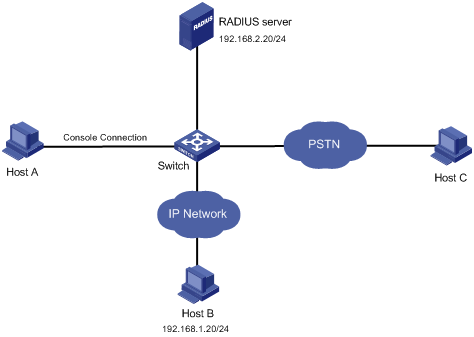
Network requirements
As shown in Figure 18, three administrators need to access the switch for switch management: one through a console port, one through an IP network, and one through a public switched telephone network (PSTN).
Configure the switch to:
· Perform no authentication for users who log in through the console port.
· Perform password authentication for users who log in through the IP network.
· Use the RADIUS server to authenticate users who log in through the PSTN, and use local authentication as the backup.
· Assign different command levels to different types of users.
Configuration procedure
# Assign IP addresses to the interfaces on the switch so that the switch and Host B can reach each other and the switch and the RADIUS server can reach each other. (Details not shown)
# Enable the Telnet service on the switch.
<Sysname> system-view
[Sysname] telnet server enable
# Configure the switch to perform no authentication for users logging in through the console port and to allow the users to use commands of privilege level 3 (all commands).
[Sysname] user-interface console 0
[Sysname-ui-console0] authentication-mode none
[Sysname-ui-console0] user privilege level 3
[Sysname-ui-console0] quit
# Configure the switch to perform password authentication for users logging in to VTY user interfaces 0 through 4. Set the password to 123, and set the privilege level of the users to 2.
[Sysname] user-interface vty 0 4
[Sysname-ui-vty0-4] authentication-mode password
[Sysname-ui-vty0-4] set authentication password cipher 123
[Sysname-ui-vty0-4] user privilege level 2
[Sysname-ui-vty0-4] quit
# Configure the switch to use AAA to authenticate users logging in to user interface VTY 5.
[Sysname] user-interface vty 5
[Sysname-ui-vty5] authentication-mode scheme
[Sysname-ui-vty5] quit
# Create a RADIUS scheme and configure the IP address and UDP port for the primary authentication server for the scheme. Make sure that the port number is consistent with that on the RADIUS server. Set the shared key for authentication packets to expert for the scheme and the RADIUS server type of the scheme to extended. Configure the switch to remove the domain name in the username sent to the RADIUS server.
[Sysname] radius scheme rad
[Sysname-radius-rad] primary authentication 192.168.2.20 1812
[Sysname-radius-rad] key authentication expert
[Sysname-radius-rad] server-type extended
[Sysname-radius-rad] user-name-format without-domain
[Sysname-radius-rad] quit
# Configure the default ISP domain system to use RADIUS scheme rad for login users and use local authentication as the backup.
[Sysname] domain system
[Sysname-isp-system] authentication login radius-scheme rad local
[Sysname-isp-system] authorization login radius-scheme rad local
[Sysname-isp-system] quit
# Add a local user named monitor, set the user password to 123, and specify to display the password in cipher text. Authorize user monitor to use the Telnet service and specify the level of the user as 1, the monitor level.
[Sysname] local-user monitor
[Sysname-luser-admin] password cipher 123
[Sysname-luser-admin] service-type telnet
[Sysname-luser-admin] authorization-attribute level 1
Command authorization configuration example
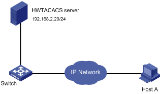
Network requirements
As shown in Figure 19, configure the switch to use the HWTACACS server to authenticate and perform command line authorization for users accessing the VTY interfaces 0 through 4, and use local authentication and authorization as the backup.
Configuration procedure
# Assign an IP address to the switch so that the switch and Host A, and the switch and the HWTACACS server can reach each other. (Details not shown)
# Enable the Telnet service on the switch.
<Sysname> system-view
[Sysname] telnet server enable
# Configure the switch to use AAA to control user access to VTY interfaces 0 through 4.
[Sysname] user-interface vty 0 4
[Sysname-ui-vty0-4] authentication-mode scheme
# Enable command authorization to restrict the command level for login users.
[Sysname-ui-vty0-4] command authorization
[Sysname-ui-vty0-4] quit
# Create an HWTACACS scheme named tac and configure the IP address and TCP port for the primary authorization server for the scheme. Make sure that the port number is consistent with that on the HWTACACS server. Set the shared key for authentication packets to expert for the scheme and the HWTACACS server type of the scheme to standard. Configure the switch to remove the domain name in the username that is sent to the HWTACACS server.
[Sysname] hwtacacs scheme tac
[Sysname-hwtacacs-tac] primary authentication 192.168.2.20 49
[Sysname-hwtacacs-tac] primary authorization 192.168.2.20 49
[Sysname-hwtacacs-tac] key authentication expert
[Sysname-hwtacacs-tac] key authorization expert
[Sysname-hwtacacs-tac] server-type standard
[Sysname-hwtacacs-tac] user-name-format without-domain
[Sysname-hwtacacs-tac] quit
# Configure the default ISP domain system to use HWTACACS scheme tac for login users and use local authorization as the backup.
[Sysname] domain system
[Sysname-isp-system] authentication login hwtacacs-scheme tac local
[Sysname-isp-system] authorization command hwtacacs-scheme tac local
[Sysname-isp-system] quit
# Add a local user named monitor, set the user password to 123, and specify to display the password in cipher text. Authorize user monitor to use the Telnet service and specify the level of the user as 1, that is, the monitor level.
[Sysname] local-user monitor
[Sysname-luser-admin] password cipher 123
[Sysname-luser-admin] service-type telnet
[Sysname-luser-admin] authorization-attribute level 1
Command accounting configuration example
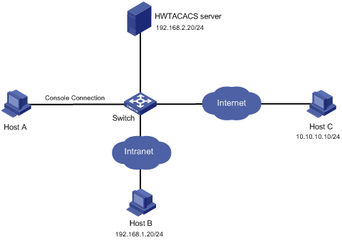
Network requirements
As shown in Figure 20, configure the switch to send commands that login users execute to the HWTACACS server to control and monitor user operations.
Configuration procedure
# Enable the Telnet service on switch.
<Sysname> system-view
[Sysname] telnet server enable
# Enable command accounting for users logging in through the console port.
[Sysname] user-interface console 0
[Sysname-ui-console0] command accounting
[Sysname-ui-console0] quit
# Enable command accounting for users logging in through Telnet or SSH.
[Sysname] user-interface vty 0 4
[Sysname-ui-vty0-4] command accounting
[Sysname-ui-vty0-4] quit
# Create an HWTACACS scheme named tac and configure the IP address and TCP port for the primary authorization server for the scheme. Make sure that the port number is consistent with that on the HWTACACS server. Set the shared key for authentication packets to expert for the scheme. Configure switch to remove the domain name in the username sent to the HWTACACS server.
[Sysname] hwtacacs scheme tac
[Sysname-hwtacacs-tac] primary accounting 192.168.2.20 49
[Sysname-hwtacacs-tac] key accounting expert
[Sysname-hwtacacs-tac] user-name-format without-domain
[Sysname-hwtacacs-tac] quit
# Create ISP domain system, and configure the ISP domain to use HWTACACS scheme tac for accounting of command line users.
[Sysname] domain system
[Sysname-isp-system] accounting command hwtacacs-scheme tac
[Sysname-isp-system] quit
Configuration preparation
Before configuration, determine the permitted or denied source IP addresses, source MAC addresses, and destination IP addresses.
Configuring source IP-based login control over Telnet users
Basic ACLs match the source IP addresses of packets, so you can use basic ACLs to implement source IP-based login control over Telnet users. Basic ACLs are numbered from 2000 to 2999. For more information about ACL, see ACL and QoS Configuration Guide.
To configure source IP-based login control over Telnet users:
|
Step |
Command |
Remarks |
|
1. Enter system view. |
system-view |
N/A |
|
2. Create a basic ACL and enter its view, or enter the view of an existing basic ACL. |
acl [ ipv6 ] number acl-number [ name name ] [match-order { config | auto } ] |
By default, no basic ACL exists. |
|
3. Configure rules for this ACL. |
rule [ rule-id ] { permit | deny } [ source { sour-addr sour-wildcard | any } | time-range time-name | fragment | logging ]* |
N/A |
|
Exit the basic ACL view. |
quit |
N/A |
|
5. Enter user interface view. |
user-interface [ type ] first-number [ last-number ] |
N/A |
|
6. Use the ACL to control user login by source IP address. |
acl [ ipv6 ] acl-number { inbound | outbound } |
· inbound—Filters incoming Telnet packets. · outbound—Filters outgoing Telnet packets. |
Configuring source and destination IP-based login control over Telnet users
Advanced ACLs can match both source and destination IP addresses of packets, so you can use advanced ACLs to implement source and destination IP-based login control over Telnet users. Advanced ACLs are numbered from 3000 to 3999. For more information about ACL, see ACL and QoS Configuration Guide.
To configure source and destination IP-based login control over Telnet users:
|
Step |
Command |
Remarks |
|
1. Enter system view. |
system-view |
N/A |
|
Create an advanced ACL and enter its view, or enter the view of an existing advanced ACL. |
acl [ ipv6 ] number acl-number [ name name ] [ match-order { config | auto } ] |
By default, no advanced ACL exists. |
|
3. Configure rules for the ACL. |
rule [ rule-id ] { permit | deny } rule-string |
N/A |
|
4. Exit advanced ACL view. |
quit |
N/A |
|
5. Enter user interface. |
user-interface [ type ] first-number [ last-number ] |
N/A |
|
6. Use the ACL to control user login by source and destination IP addresses. |
acl [ ipv6 ] acl-number { inbound | outbound } |
· inbound—Filters incoming Telnet packets. outbound—Filters outgoing Telnet packets. |
Configuring source MAC-based login control over Telnet users
Ethernet frame header ACLs can match the source MAC addresses of packets, so you can use Ethernet frame header ACLs to implement source MAC-based login control over Telnet users. Ethernet frame header ACLs are numbered from 4000 to 4999. For more information about ACL, see ACL and QoS Configuration Guide.
To configure source MAC-based login control over Telnet users:
|
Step |
Command |
Remarks |
|
1. Enter system view. |
system-view |
N/A |
|
2. Create an Ethernet frame header ACL and enter its view. |
acl number acl-number [ name name ] [ match-order { config | auto } ] |
By default, no Ethernet frame header ACL exists. |
|
3. Configure rules for the ACL. |
rule [ rule-id ] { permit | deny } rule-string |
N/A |
|
4. Exit the advanced ACL view. |
quit |
N/A |
|
5. Enter user interface view. |
user-interface [ type ] first-number [ last-number ] |
N/A |
|
6. Use the ACL to control user login by source MAC address. |
acl acl-number inbound |
inbound: Filters incoming Telnet packets. |
|
|
NOTE: The configuration does not take effect if the Telnet client and server are not in the same subnet. |
Source MAC-based login control configuration example
Network requirements
As shown in Figure 21, configure an ACL on the switch to permit only incoming Telnet packets sourced from Host A and Host B.

Configuration procedure
# Configure basic ACL 2000, and configure rule 1 to permit packets sourced from Host B, and rule 2 to permit packets sourced from Host A.
<Sysname> system-view
[Sysname] acl number 2000 match-order config
[Sysname-acl-basic-2000] rule 1 permit source 10.110.100.52 0
[Sysname-acl-basic-2000] rule 2 permit source 10.110.100.46 0
[Sysname-acl-basic-2000] quit
# Reference ACL 2000 in user interface view to allow Telnet users from Host A and Host B to access the switch.
[Sysname] user-interface vty 0 4
[Sysname-ui-vty0-4] acl 2000 inbound