- Table of Contents
-
- 01-Fundamentals Configuration Guide
- 00-Preface
- 01-CLI Configuration
- 02-Login Management Configuration
- 03-FTP and TFTP Configuration
- 04-File System Management
- 05-Configuration File Management Configuration
- 06-Software Upgrade Configuration
- 07-ISSU Configuration
- 08-Device Management Configuration
- 09-Automatic Configuration
- Related Documents
-
| Title | Size | Download |
|---|---|---|
| 06-Software Upgrade Configuration | 342.82 KB |
Contents
Upgrading BootWare on the BootWare menu·
Upgrading software through the console port (Xmodem)
Upgrading software through the management Ethernet port (TFTP)
Upgrading software through the management Ethernet port (FTP)
Upgrading system software image through a system reboot
Specifying the system software image to be used at the next boot
Upgrading system software image on the SMB
Installing a patch in one step
Installing a patch step by step
Uninstalling a patch in one step
Uninstalling a patch step by step
Upgrading MBUS daughter card software
Upgrading the logic for a card
Upgrading the PSU software for a card·
Upgrading the clock monitor software
Displaying and maintaining software upgrade configuration
System software image upgrade example (standalone mode)
System software image upgrade example (IRF mode)
Scheduled upgrade configuration example
|
|
NOTE: The switch operates in Intelligent Resilient Framework (IRF) or standalone (the default) mode. For more information about the IRF mode, see IRF Configuration Guide. |
Switch software overview
Switch software comprises the BootWare, system software, the maintenance bus (MBUS) daughter card software, and the logic for a card.
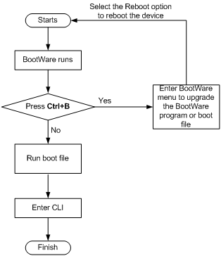
After powered on, the switch runs the BootWare image, initializes the hardware, and displays the hardware information. Then the switch runs the system software image. The system software image provides drivers and adaption for hardware, and implements service features. The BootWare image and system software image are required for the startup and running of a switch. Figure 1 illustrates their relationship.
Figure 1 Relationship between the BootWare and the system software images
Software upgrade task list
|
Task |
Remarks |
|
Optional |
|
|
Optional |
|
|
Optional |
|
|
Optional |
|
|
Optional |
|
|
Optional |
|
|
Optional |
|
|
Optional |
|
|
NOTE: · The system software image file (with the file extension.bin) comprises the BootWare image and MBUS daughter card software, which are automatically upgraded when the system software image file is upgraded. You can also manually upgrade BootWare image and MBUS daughter card software by following the above configuration tasks. · The BootWare and system software images can be upgraded by using the BootWare menu, at the command line interface (CLI), or by installing hotfixes. This document only describes how to upgrade them at the CLI and by installing hotfixes. For more information about upgrading them by using the BootWare menu, see the installation guide of the switch. |
Upgrading BootWare on the BootWare menu
|
|
CAUTION: · Never hot-plug a CF card after you enter the BootWare menu. · A CF card can be used only after the cover of the CF card is correctly installed. |
Entering the BootWare menu
After powering on the switch, run the BootWare image first and the terminal displays the following information:
DDR2 SDRAM test successful.
System is starting...
Booting Normal Extend BootWare
The Extend BootWare is self-decompressing..........................
Done!
****************************************************************************
* *
* H3C S9500E BootWare, Version 1.02 *
* *
****************************************************************************
Copyright (c) 2004-2010 Hangzhou H3C Technologies Co., Ltd.
Compiled Date : Aug 9 2010
CPU Type : MPC8548E
CPU L1 Cache : 32KB
CPU L2 Cache : 512KB
CPU Clock Speed : 1000MHz
Memory Type : DDR2 SDRAM
Memory Size : 1024MB
Memory Speed : 400MHz
BootWare Size : 4MB
Flash Size : 128MB
cfa0 Size : 247MB
NVRAM Size : 1024KB
BASIC CPLD Version : 001F
EXTEND CPLD Version : 001F
PCB Version : Ver.A
Board self testing...........................
Board steady testing... [ PASS ]
Board SlotNo... [ 0 ]
Subcard exist testing... [ FAIL ]
DX246 testing... [ PASS ]
PHY88E1111 testing... [ PASS ]
CPLD1 testing... [ PASS ]
CPLD2 testing... [ PASS ]
NS16550 register testing... [ PASS ]
The default switch's Mac address... [00:e0:fc:00:95:12]
CF Card testing... [ PASS ]
BootWare Validating...
Press Ctrl+B to enter extended boot menu...
|
|
NOTE: · You must press Ctrl+B in three seconds after the prompt “Press Ctrl+B to enter Boot menu...” appears. Otherwise, the system will enter the application decompression process, instead of the extended BootWare menu. To access the extended BootWare menu after the switch enters the program decompression process, restart the switch. · The output information is for reference only. |
After pressing Ctrl+B, the system prompts you to enter the BootWare password. Enter the correct password (superman by default) and the system enters the BootWare menu.
|
|
CAUTION: Keep in mind the latest BootWare password while using the switch. You can use the super user password to enter the system and reset the BootWare password in the case of password loss. |
Note: The current operating device is cfa0
Enter < Storage Device Operation > to select device.
===========================<EXTEND-BOOTWARE MENU>=========================
|<1> Boot System |
|<2> Enter Serial SubMenu |
|<3> Enter Ethernet SubMenu |
|<4> File Control |
|<5> Modify BootWare Password |
|<6> BootWare Operation Menu |
|<7> Clear Super Password |
|<8> Storage Device Operation |
|<9> Product Special Operation |
|<0> Reboot |
==========================================================================
Enter your choice(0-9):2
When loading the system software image through the BootWare menu, you must configure correct serial interface parameters such as the bits per second, data bit, parity, stop bits, and flow control. Otherwise, the HyperTerminal does not respond.
Upgrading software through the console port (Xmodem)
Introduction to Xmodem
As a file transfer protocol, Xmodem is broadly applied for its simplicity and good performance. It transmits files through serial interfaces, supporting 128 bytes and 1 KB in terms of data unit, checksum and CRC in terms of checking mode, and multiple retransmissions (usually ten attempts) in the event that packet errors are found.
Xmodem completes transmission by the receiving program (receiver) and the sending program (sender). In Xmodem, the transmission begins with the sending of negotiation characters from the receiver for check mode negotiation. After passing the negotiation, the sender is allowed to send the first data packet. Upon the receipt of the complete packet, the receiver checks the packet using the agreed checking mode and will send an ACK if the packet has passed the check and a NAK if not. Receiving the ACK, the sender will send the next packet; receiving the NAK instead, the sender will retransmit the previously sent packet.
Xmodem application
1. On the BootWare menu, enter 2, and press Enter. You will enter the serial interface submenu:
===========================<Enter Serial SubMenu>==========================
|Note:the operating device is cfa0 |
|<1> Download Application Program To SDRAM And Run |
|<2> Update Main Application File |
|<3> Update Backup Application File |
|<4> Update Secure Application File |
|<5> Update User Private File |
|<6> Modify Serial Interface Parameter |
|<0> Exit To Main Menu |
===========================================================================
Enter your choice(0-6):
2. Enter 6 in the serial interface submenu and press Enter to access the serial interface parameter setting submenu:
===============================<BAUDRATE SET>=============================
|Note:'*'indicates the current baudrate |
| Change The HyperTerminal's Baudrate Accordingly |
|---------------------------<Baudrate Avaliable>---------------------------|
|<1> 9600(Default)* |
|<2> 19200 |
|<3> 38400 |
|<4> 57600 |
|<5> 115200 |
|<0> Exit |
===========================================================================
Enter your choice(0-5):1
3. Select the appropriate downloading speed as needed. For example, enter 1 to select the downloading speed of 9600 bps.
|
|
NOTE: The default baud rate of the console port is 9600 bps. The system uses the default setting at reboot even if the baud rate was modified. |
4. At the prompt displayed in the previous step, change the baud rate on the console terminal to the same one selected for software downloading, disconnect the terminal and connect it again, press Enter, and the terminal will enter the serial interface submenu again:
===========================<Enter Serial SubMenu>==========================
|Note:the operating device is cfa0 |
|<1> Download Application Program To SDRAM And Run |
|<2> Update Main Application File |
|<3> Update Backup Application File |
|<4> Update Secure Application File |
|<5> Update User Private File |
|<6> Modify Serial Interface Parameter |
|<0> Exit To Main Menu |
===========================================================================
Enter your choice(0-6):2
|
|
NOTE: · After changing the baud rate, you must close the terminal emulation program and start it again for at least once in order to validate the new baud rate. · In a Windows 98 operating system environment, you can perform the operations of disconnection and reconnection after changing the baud rate. In a Windows 2000 operating system, however, you must disconnect the terminal before setting the baud rate and connect the terminal after finishing the work. |
5. Select the operation to be implemented. For example, enter 2 to download the file into the switch, press Enter, and the system will display the following information on the terminal:
Please Select File .
XMODEM downloading ...CCC
6. Select Transfer > Send File in the terminal window. Click Browse in the pop-up dialog box (shown in the following figure), select the desired application, and change the protocol used for downloading to Xmodem.
Figure 2 Send file dialog box
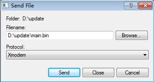
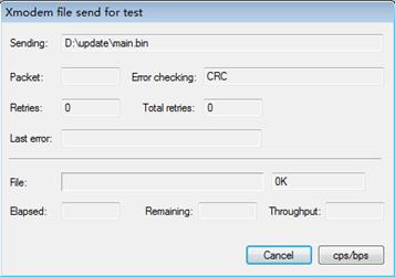
7. Click Send and the following interface pops up.
Figure 3 Sending file page
8. After downloading the program successfully, the system will access the serial interface submenu again, and you can make selection as needed. The details will not be covered here.
Upgrading software through the management Ethernet port (TFTP)
Introduction to TFTP
Trivial file transfer protocol (TFTP) is well suited to the file transfer between a server and a client that do not need complex interaction.
In TFTP, the transmission is initiated by the client. When downloading a file, the client sends a read request packet to the TFTP server, receives the data packets from the server, and sends the ACK to the server. When uploading a file, the client sends a write request packet to the TFTP server, then sends the data packets to the server, and receives the ACK from the server. The TFTP transmission files have two forms, for example, binary for program transmission and ASCII for text transmission.
In the following example, the switch works as a TFTP client
TFTP upgrade procedure
1. Connect the switch to a PC where the desired file is located via the management Ethernet port. In this case, you should know the IP address of the PC. Connect the console port on the switch to another PC or the same PC.
2. Run the TFTP Server program on the PC connected to the management Ethernet port, and specify the path for upgrading the application files.
3. Run the terminal emulation program on the PC connected to the console port, and boot the switch to access the BootWare menu.
4. Select 3 on the BootWare menu. Press Enter and the system will access the Ethernet submenu.
==========================<Enter Ethernet SubMenu>=========================
|Note:the operating device is cfa0 |
|<1> Download Application Program To SDRAM And Run |
|<2> Update Main Application File |
|<3> Update Backup Application File |
|<4> Update Secure Application File |
|<5> Update User Private File |
|<6> Modify Ethernet Parameter |
|<0> Exit To Main Menu |
|<Ensure The Parameter Be Modified Before Downloading!> |
===========================================================================
Enter your choice(0-6):6
5. Enter 6 in the Ethernet submenu to modify the Ethernet interface parameters. The system displays the following information:
==========================<ETHERNET PARAMETER SET>=========================
|Note: '.' = Clear field. |
| '-' = Go to previous field. |
| Ctrl+D = Quit. |
===========================================================================
|
|
NOTE: Use shortcut key . to clear the current input, shortcut key - to return to the previous field, or shortcut key Ctrl+D to quit the parameter setting page. |
Protocol (FTP or TFTP) :TFTP
Load File Name :bootware
:test.bin
Target File Name :bootware
:test.bin
Server IP Address :192.168.1.1
Local IP Address :192.168.1.253
Gateway IP Address :0.0.0.0
6. After you provide the required information, the system accesses the Ethernet interface submenu again:
==========================<Enter Ethernet SubMenu>=========================
|Note:the operating device is cfa0 |
|<1> Download Application Program To SDRAM And Run |
|<2> Update Main Application File |
|<3> Update Backup Application File |
|<4> Update Secure Application File |
|<5> Update User Private File |
|<6> Modify Ethernet Parameter |
|<0> Exit To Main Menu |
|<Ensure The Parameter Be Modified Before Downloading!> |
===========================================================================
Enter your choice(0-6):2
7. Select 2 to download the file to the switch, and press Enter. The system will display the following information on the terminal screen:
Loading...................................................................
..........................................................................
..........................................................................
..........................................................................
..................................Done!
47979456 bytes downloaded!
Updating File cfa0:/test.bin..............................................
..........................................................................
..........................................................................
..........................................................................
...............................................
..Done!
8. The information displayed in the last step means a successful file downloading operation. In this case, the system accesses the Ethernet interface submenu again and the user can make selection as needed. The details will not be covered here.
Upgrading software through the management Ethernet port (FTP)
Introduction to FTP
The applications of the S9500E Switch Series can also be upgraded through the Ethernet port using FTP.
In the following example, the switch works as an FTP client.
Upgrade procedure
1. Connect the switch to the PC containing the desired file via the management Ethernet port. In this case, you should know the IP address of the PC. Connect the console port on the switch to another PC or the same PC.
2. Run FTP Server on the PC connected to the management Ethernet port, specify the path of the upgrading file, and set the login username and password.
3. Run the terminal emulation program on the PC connected to the console port, and boot the switch to access the BootWare menu.
4. For Steps 4 to 8, see the corresponding steps in the upgrading procedure via TFTP for reference.
Modifying file attributes
After downloading the system software image through the BootWare menu, you must specify it as the system software image to be used at the next boot.
1. Select 4 in the BootWare menu to enter the file control submenu.
===========================<EXTEND-BOOTWARE MENU>==========================
|<1> Boot System |
|<2> Enter Serial SubMenu |
|<3> Enter Ethernet SubMenu |
|<4> File Control |
|<5> Modify BootWare Password |
|<6> BootWare Operation Menu |
|<7> Clear Super Password |
|<8> Storage Device Operation |
|<9> Product Special Operation |
|<0> Reboot |
===========================================================================
Enter your choice(0-9): 4
===============================<File CONTROL>==============================
|Note:the operating device is cfa0 |
|<1> Display All File(s) |
|<2> Set Application File type |
|<3> Delete File |
|<0> Exit To Main Menu |
===========================================================================
2. Select 2 to enter the interface for setting the application file attribute.
Enter your choice(0-3): 2
'M' = MAIN 'B' = BACKUP 'S' = SECURE 'N/A' = NOT ASSIGNED
===========================================================================
|NO. Size(B) Time Type Name |
|1 38811764 Jul/07/2010 10:19:42 N/A cfa0:/test.bin |
|2 47979456 Aug/27/2010 10:00:42 M cfa0:/SWITCH_backup.bin |
|0 Exit |
===========================================================================
3. Select the file number and modify the file attribute.
Enter file No:2
Modify the file attribute:
===========================================================================
|<1> +Main |
|<2> -Main |
|<3> +Backup |
|<4> -Backup |
|<0> Exit |
===========================================================================
Enter your choice(0-4):1
Set the file attribute success!
Modifying switch working mode
To modify the device working mode on the BootWare menu:
1. Select 9 on the BootWare menu to enter the product special operation submenu.
===========================<EXTEND-BOOTWARE MENU>=========================
|<1> Boot System |
|<2> Enter Serial SubMenu |
|<3> Enter Ethernet SubMenu |
|<4> File Control |
|<5> Modify BootWare Password |
|<6> BootWare Operation Menu |
|<7> Clear Super Password |
|<8> Storage Device Operation |
|<9> Product Special Operation |
|<0> Reboot |
==========================================================================
Enter your choice(0-9): 9
========================<PRODUCT SPECIAL OPERATION>=========================
|<1> Modify Chassis ID Operation |
|<2> Modify Working Mode |
|<3> Modify PCL Key |
|<4> Skip Current System Configuration |
|<0> Exit To Main Menu |
============================================================================
2. Select 1 to enter the submenu for modifying the chassis ID.
Enter your choice(0-4): 1
==============================<CHASSIS ID SET>==============================
| Note:'*'indicates the current chassis ID |
| Change The Chassis ID Accordingly |
|-------------------------<Chassis ID Avaliable>---------------------------|
|<1> 0* |
|<2> 1 |
|<3> 2 |
|<4> 3 |
|<5> 4 |
|<0> Exit |
============================================================================
3. Select the chassis ID and modify the working mode of the switch corresponding to the chassis ID. 0 indicates the independent working mode; 1, 2, 3, and 4 indicate the member IDs in the IRF; the asterisk (*) marks the current member ID. For information about switch working modes, see the chapter “Managing the device.”
Enter your choice(0-5): 3
Chassis ID has been changed to 2.
The current chassis ID is 2.
Modifying system working mode
To modify the system working mode through the BootWare menu:
1. Select 9 in the BootWare menu to enter the product special operation submenu.
===========================<EXTEND-BOOTWARE MENU>=========================
|<1> Boot System |
|<2> Enter Serial SubMenu |
|<3> Enter Ethernet SubMenu |
|<4> File Control |
|<5> Modify BootWare Password |
|<6> BootWare Operation Menu |
|<7> Clear Super Password |
|<8> Storage Device Operation |
|<9> Product Special Operation |
|<0> Reboot |
==========================================================================
Enter your choice(0-9): 9
========================<PRODUCT SPECIAL OPERATION>=========================
|<1> Modify Chassis ID Operation |
|<2> Modify Working Mode |
|<3> Modify PCL Key |
|<4> Skip Current System Configuration |
|<0> Exit To Main Menu |
============================================================================
2. Select 2 to enter the submenu for modifying the system working mode.
Enter your choice(0-4):2
=============================<WORKING MODE SET>=============================
|Note:'*'indicates the current working mode |
| Change The Working Mode Accordingly |
|-------------------------<Working Mode Avaliable>-------------------------|
|<1> Standard Mode* |
|<2> BridgeE Mode |
|<3> RouteE Mode |
|<4> Advance Mode |
|<5> Configurable Mode |
|<0> Exit |
============================================================================
3. Select the working mode of the system. The asterisk (*) marks the current working mode. Currently, the Configurable Mode is not supported. For information about switch working modes, see the chapter “Managing the device.”
Enter your choice(0-5): 2
=============================<WORKING MODE SET>=============================
|Note:'*'indicates the current working mode |
| Change The Working Mode Accordingly |
|-------------------------<Working Mode Avaliable>-------------------------|
|<1> Standard Mode |
|<2> BridgeE Mode* |
|<3> RouteE Mode |
|<4> Advance Mode |
|<5> Configurable Mode |
|<0> Exit |
============================================================================
Enter your choice(0-5):
Upgrading BootWare at the CLI
The switch runs the BootWare image, tests and initializes the hardware, displays hardware parameters, and then runs the system software image. During the operation of the switch, you can use the BootWare in the storage medium to upgrade those that are running on the switch.
|
|
NOTE: As part of the system software image file (with the file extension.bin), the BootWare image is automatically upgraded when the system software image is upgraded. You can also manually upgrade BootWare by executing the bootrom update file command. |
To upgrade BootWare on a card:
|
Task |
Command |
Remarks |
|
Upgrade BootWare on a card (standalone mode). |
bootrom update file file-url slot slot-number-list |
Available in user view. |
|
Upgrade BootWare on a card (IRF mode). |
bootrom update file file-url chassis chassis-number slot slot-number-list |
To upgrade BootWare of the operation, administration, and maintenance (OAM) modules on the main boards:
|
Task |
Command |
Remarks |
|
Upgrade BootWare of the OAM modules on the active main board (AMB) and standby main board (SMB) (standalone mode). |
oam-bootrom update file file-url slot slot-number |
Available in user view. |
|
Upgrade BootWare of the OAM modules on the AMB and SMB (IRF mode). |
oam-bootrom update file file-url chassis chassis-number slot slot-number |
|
|
NOTE: · Restart the switch to validate the upgraded BootWare. · If the switch operates in standalone mode, save the BootWare file in the root directory of the storage media on the AMB to execute the bootrom update command successfully. · If the switch operates in IRF mode, save the BootWare file in the root directory of the storage media on a member switch to execute the bootrom update command successfully. |
Upgrading system software image through a system reboot
To upgrade system software image: (In standalone mode)
1. Save the system software image to the root directory of the AMB's storage medium by using a method such as FTP or TFTP.
2. Copy the new system software image to the root directory of the SMB's storage medium.
3. Use commands to specify the system software image to be used at the next boot of the AMB and SMB respectively. For more information, see “Specifying the system software image to be used at the next boot.”
4. Reboot the switch to make the new system software image take effect.
To upgrade system software image: (In IRF mode)
1. Save the system software image to the root directory of the master switch's storage medium by using a method such as FTP or TFTP.
2. Copy the new system software image to the root directory of the storage medium of the other main boards in the IRF fabric, including the SMB of the master, AMB of the slave, and SMB of the slave.
3. Use commands to specify the system software image to be used at the next boot of all the main boards of the IRF fabric. For more information, see “Specifying the system software image to be used at the next boot.”
4. Reboot the switch to make the new system software image take effect.
Specifying the system software image to be used at the next boot
When multiple BootWare files are available on the storage media, you can specify a system software image to be used at the next switch boot. A main system software image is used to boot a switch and a backup system software image is used to boot a switch only when a main boot file is unavailable
To upgrade the system software image:
|
Task |
Command |
Remarks |
|
Specify the system software image to be used at the next switch boot (standalone mode). |
boot-loader file file-url slot slot-number { main | backup } |
Available in user view. |
|
Specify the system software image to be used at the next switch boot (IRF mode). |
boot-loader file file-url chassis chassis-number slot slot-number { main | backup } |
|
CAUTION: · You must save the file for the next switch boot in the root directory of the switch. You can copy or move a file to change the path of it to the root directory. For a switch that supports storage media partition, the file must be saved on the first partition. · Only the file saved on the flash or the CF card can be specified as the system software image to be used at the next boot through the boot-loader command. · To successfully execute the boot-loader command, save the file to be used at the next switch boot in the root directory of the flash or the CF card on a member switch. |
Upgrading system software image on the SMB
The SMB cannot correctly work if it has a different software version than the AMB, and you must synchronize them to have the same system software version.
Use the display device command to check the state of the SMB. If its state is Fault, upgrade the SMB at the Boot menu or unplug the SMB and upgrade it. If its state is Slave, perform the boot-loader update command, and the system automatically upgrades the system software on the SMB to be the same as the AMB, and reboots the SMB with the new system software image.
To upgrade system software on the SMB:
|
Task |
Command |
Remarks |
|
Upgrade system software image for the SMB. |
boot-loader update slot slot-number |
Available in user view. |
|
|
CAUTION: · The boot-loader update slot slot-number command is available when the switch operates in standalone mode. To upgrade system software image when the switch operates in IRF mode, use the boot-loader file file-url chassis chassis-number slot slot-number { main | backup } command. · Before you upgrade system software for the SMB, check that the SMB has sufficient storage space for the new system software image. If the sum of the free space and the space occupied by the old system software image is greater than the size of the new system software image, the device automatically deletes the old system software image before the upgrade. Otherwise, the upgrade will fail. |
Installing hotfixes
A hotfix repairs software defects on a switch. A hotfix upgrades the software without interrupting running services or rebooting the switch.
Basic concepts in hotfix
Patch and patch file
A patch, also called patch unit, is a package to fix software defects. Generally, patches are released as patch files. A patch file may contain one or more patches. After being loaded from the storage medium to the memory patch area, each patch is assigned a unique number, which starts from 1, for identification, management and operation. For example, if a patch file has three patch units, they are numbered as 1, 2, and 3 respectively.
Incremental patch
An incremental patch means that the patch is dependent on the previous patch units. An incremental patch means that the patch is dependent on the previous patch units. For example, if a patch file has three patches, patch 3 can be running only after patch 1 and 2 take effect. You cannot run patch 3 separately.
The patches that have been released are all incremental patches.
Common patch and temporary patch
There are common and temporary patches:
· Common patches are formally released through the version release flow.
Common patches always include the functions of the previous temporary patches. The patch type affects only the patch loading process; the system deletes all the temporary patches before it loads the common patch.
Patch package file
A patch package file contains multiple patches released at the same time. Patch package file upgrade is an improvement of patch file upgrade.
The filename of a patch file is strictly defined. Each type of hardware corresponds to a patch file with a fixed filename, which cannot be changed. When the software of a component needs to be upgraded, you need to download the corresponding patch file, and rename the file as the filename pre-defined for the hardware. If the filename does not match, the upgrade operation fails. If there are multiple components, you need to repeat this operation multiple times.
When you use a patch package file to upgrade software, you need to download the package file and execute the file only once, and all components of the device can be upgraded, simplifying patch operation and patch version management.
Patch status
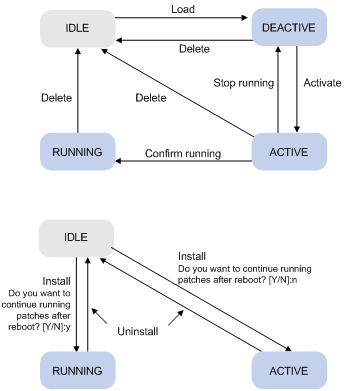
Each patch has a status, which can be switched only by commands. The relationship between patch state changes and command actions is shown in Figure 4. The patch can be in state of IDLE, DEACTIVE, ACTIVE, and RUNNING. Load, run temporarily, confirm running, stop running, delete, install, and uninstall are operations and they correspond to the following commands: patch load, patch active, patch run, patch deactive, patch delete, patch install, and undo patch install. For example, if you execute the patch active command for the patches in DEACTIVE state, the patches turn to ACTIVE state.
Figure 4 Relationship between patch state changes and command actions
|
|
NOTE: Information about patch states is saved in file patchstate on the flash. H3C recommends that you do not operate this file. |
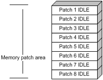
· IDLE state
Patches in IDLE state are not loaded. You cannot install or run the patches, as shown in Figure 5 (In this example, the memory patch area can load up to eight patches).
Figure 5 Patches are not loaded to the memory patch area
|
|
NOTE: The memory patch area supports up to 200 patches. |
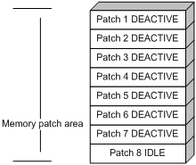
· DEACTIVE state
Patches in DEACTIVE state have been loaded to the memory patch area but have not yet run in the system. Suppose that there are seven patches in the patch file to be loaded. After the seven patches successfully pass the version check and CRC check, they are loaded to the memory patch area and are in DEACTIVE state. At this time, the patch states in the system are as shown in Figure 6.
Figure 6 A patch file is loaded to the memory patch area
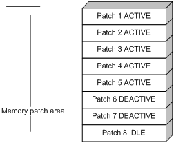
· ACTIVE state
Patches in ACTIVE state have run temporarily in the system and become DEACTIVE after system reboot. For the seven patches in Figure 6, if you activate the first five patches, their states change from DEACTIVE to ACTIVE. The patch states in the system are as shown in Figure 7.
The patches that are in ACTIVE state are in DEACTIVE state after system reboot.
Figure 7 Patches are activated
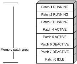
· RUNNING state
After you confirm the running of ACTIVE patches, the state of the patches become RUNNING and are in RUNNING state after system reboot. If you confirm running the first three patches, for the five patches in Figure 7, their states change from ACTIVE to RUNNING. The patch states of the system are shown in Figure 8.
The patches that are in RUNNING state are still in RUNNING state after system reboot.
Hotfix task list
|
Task |
Remarks |
|
|
Install patches. |
Use either approach. The step-by-step patch installation allows you to control the patch status. |
|
|
Uninstall patches. |
Use either approach. The step-by-step patch uninstallation allows you to control the patch status. |
|
|
|
CAUTION: Make sure the version of the patch files consistent with that of the current software before loading, activating, and running the patches. |
Configuration prerequisites
Patches are released per switch model or card type. Before patching the system, you need to save the appropriate patch files to the storage media of the switch by using FTP or TFTP. When saving the patch files, follow these guidelines:
· The patch files match the switch model and software version. If they are not matched, the hotfixing operation fails.
· Name a patch file properly. Otherwise, the system cannot locate the patch file and the hotfixing operation fails. The name is in the format of "patch_PATCH-FLAG suffix.bin". The PATCH-FLAG is pre-defined. The value of the version field (using the display patch information command) represent the PATCH-FLAG suffix. The system searches the root directory of the storage medium (flash by default) for patch files based on the PATCH-FLAG. If there is a match, the system loads patches to or install them on the memory patch area.
|
|
NOTE: The loading and installation are performed on all cards that are in position and OAM CPU, so before these operations, save the patch files for the active main board (AMB) and interface card to the root directory of the AMB's storage media, and save the patch files for the standby main board (SMB) to the root directory of the SMB's storage media. Make sure the patch files saved on the AMB and SMB are the same. |
Installing a patch in one step
To install patches in one step, execute the patch install command with specifying either the directory where the patch file locates or the filename of the patch package.
After you execute the command, the system displays the message "Do you want to continue running patches after reboot? [Y/N]:"
· Entering y or Y: All the specified patches are installed, and turn to RUNNING state from IDLE. This equals execution of the commands patch location, patch load, patch active, and patch run. The patches remain RUNNING after system reboot.
· Entering n or N: All the specified patches are installed and turn to ACTIVE state from IDLE. This equals execution of the commands patch location, patch load and patch active. The patches turn to DEACTIVE state after system reboot.
To install a patch package, save the patch package file to the storage media of the AMB. The SMB and all interface cards will load the patch file from the AMB.
To install the patches in one step:
|
Step |
Command |
|
1. Enter system view. |
system-view |
|
2. Install the patches in one step. |
patch install patch-location |
|
|
NOTE: · The loading and installation are performed on all cards that are in position and OAM CPU. Before loading and installing, save the patch files for the AMB and interface card to the root directory of the AMB's storage medium, and save the patch files for the SMB to the root directories of the SMB's storage medium. Make sure the patch files saved on the AMB and SMB are the same. · The patch matches the card type and software version. · The patch install command changes the patch file location specified with the patch location command to the directory specified by the patch-location argument of the patch install command. |
Installing a patch step by step
Step-by-step patch installation task list
|
Task |
Remarks |
|
Optional. To install a patch package, skip this step. |
|
|
Required. |
|
|
Required. |
|
|
Optional. |
Configuring the patch file location
If you save the patch files to other storage media except the flash on the switch, you need to specify the directory where the patch files locate with the patch-location argument. Then the system loads the appropriate patch files from the specified directory. If the switch has only one storage medium, you do not need to execute this command.
To configure the patch file location:
|
Step |
Command |
Remarks |
|
1. Enter system view. |
system-view |
N/A |
|
2. Configure the patch file location. |
patch location patch-location |
Optional. flash: by default. |
|
|
NOTE: · The directory specified by the patch-location argument must exist on both the AMB and SMB. If the SMB does not have such directory, the system cannot locate the patch files on the original SMB after a switchover. · The patch install command changes patch file location specified with the patch location command to the directory specified by the patch-location argument of the patch install command. For example, if you execute the patch location xxx command and then the patch install yyy command, the patch file location automatically changes from xxx to yyy. |
Loading a patch file
Loading the correct patch files is the basis of other hotfixing operations.
Different types of cards need different patch files. The patch files for the main board, interface card, and OAM sub card are patch_mr.bin, patch_lc.bin, and patch_oam.bin respectively.
The AMB and SMB get their patch files from their own storage medium.
The system loads a patch file from the flash by default.
|
|
CAUTION: · Set the file transfer mode to binary mode before using FTP or TFTP to upload/download patch files to/from the flash of the switch. Otherwise, patch file cannot be parsed properly. · To hotfix a switch with AMB and SMBs, make sure that the patch files on the two boards are the same. Otherwise, the switch cannot backup the patch states, resulting in patch state loss. |
To load a patch file:
|
Step |
Command |
|
1. Enter system view. |
system-view |
|
2. Load the patch file from the storage medium to the memory patch area (standalone mode). |
patch load slot slot-number |
|
3. Load the patch file from the storage medium to the memory patch area (IRF mode). |
patch load chassis chassis-number slot slot-number |
Activating patches
After you activate a patch, the patch will take effect and is in the test-run stage. After the switch is reset or rebooted, the patch becomes invalid.
If you find that an ACTIVE patch is of some problem, you can reboot the switch to deactivate the patch, so as to avoid a series of running faults resulting from patch error.
To activate patches:
|
Step |
Command |
|
1. Enter system view. |
system-view |
|
2. Activate the specified patches (standalone mode). |
patch active patch-number slot slot-number |
|
3. Activate the specified patches (IRF mode). |
patch active patch-number chassis chassis-number slot slot-number |
Running patches
After you run a patch, the patch state becomes RUNNING, and the patch is in the normal running stage. After the switch is reset or rebooted, the patch is still valid.
To run the patches:
|
Step |
Command |
|
1. Enter system view. |
system-view |
|
2. Run the specified patches (standalone mode). |
patch run patch-number [ slot slot-number ] |
|
3. Run of the specified patches (IRF mode). |
patch run patch-number [ chassis chassis-number slot slot-number ] |
|
|
NOTE: This operation is applicable to patches in ACTIVE state only. |
Uninstalling a patch in one step
You can use the undo patch install command to uninstall all patches from all the cards and OAM CPU. The patches then turn to IDLE state. This equals the execution of the commands patch deactive and patch delete on each card and OAM CPU.
To uninstall the patches in one step:
|
Step |
Command |
Remarks |
|
1. Enter system view. |
system-view |
N/A |
|
2. Uninstall the patches. |
undo patch install |
Deactivate all the patches and delete them from the memory patch area. |
Uninstalling a patch step by step
Step-by-step patch uninstallation task list
|
Task |
Remarks |
|
Required |
|
|
Required |
Stopping running patches
After you stop running a patch, the patch state becomes DEACTIVE, and the system runs the way it did before it was installed with the patch.
To stop running patches:
|
Step |
Command |
|
1. Enter system view. |
system-view |
|
2. Stop running the specified patches (standalone mode). |
patch deactive patch-number slot slot-number |
|
3. Stop running the specified patches (IRF mode). |
patch deactive patch-number chassis chassis-number slot slot-number |
Deleting patches
Deleting patches only deletes the patches from the memory patch area, and does not delete them from the storage medium. The patches turn to IDLE state after this operation. After a patch is deleted, the system runs the way it did before it was installed with the patch.
To delete patches:
|
Step |
Command |
|
1. Enter system view. |
system-view |
|
2. Delete the specified patches from the memory patch area (standalone mode). |
patch delete patch-number slot slot-number |
|
3. Delete the specified patches from the memory patch area (IRF mode). |
patch delete patch-number chassis chassis-number slot slot-number |
Upgrading MBUS daughter card software
Typically, the MBUS daughter card software is automatically upgraded when the system software image is upgraded. If the auto-upgrade fails, you can use the following command to upgrade it.
To upgrade MBUS daughter card software:
|
Task |
Command |
Remarks |
|
Upgrade the MBUS daughter card software on the specified card (standalone mode). |
mbus update [ file file-url ] slot slot-id |
Available in user view. |
|
Upgrade the MBUS daughter card software on the specified card (IRF mode). |
mbus update [ file file-url ] chassis chassis-number slot slot-number |
|
|
CAUTION: · In the software upgrade process of an MBUS daughter card, do not perform an active/standby switchover of the main boards, power off the switch, or restart or swap the AMB. · When the switch operates in IRF mode, to upgrade the MBUS daughter card software on the master, you must save the upgrade file to the directory on the storage medium on the AMB or SMB of the master. To upgrade the MBUS daughter card software on the slave, you must save the upgrade file to the directory on the storage medium on the AMB of the salve. Otherwise, the upgrade process fails. |
Upgrading the logic for a card
If the logic for a card fails (such as upgrade failure), use the following commands to load a new logic.
Upgrading the logic for a card
To upgrade card logics:
|
Task |
Command |
Remarks |
|
Upgrade the logic for the specified card (standalone mode). |
logic update bymbus [ file filename ] slot slot-number logicid logicid |
Available in user view. Argument logicid specifies the logic type: · 0—Upgrades the logic for a base card. · 1—Upgrades the logic for the operation, administration, and maintenance (OAM) module on a main board, or the logic for the CPU on an interface card. · 2—Upgrades the logic for the NP on a base card. (Only supported by LSR1LN2BNL1 at present.) |
|
Upgrade the logic for the specified card (IRF mode). |
logic update bymbus [ file filename ] chassis chassis-number slot slot-number logicid logicid |
Upgrading the logic for the CPU on a base card or the logic for a subcard
To upgrade the logic for the CPU on a base card or the logic for a subcard:
|
Task |
Command |
Remarks |
|
Upgrade the logic for the CPU on a base card or the logic for a subcard. |
logic update [ file filename ] slot slot-number [ subslot subslot-number ] logicid logicid |
Available in user view. logicid specifies the logic type, which can be either 1 or 4. · 1: Upgrades the logic for the CPU on a base card. · 4: Upgrades the logic for a subcard. |
|
|
CAUTION: · In the logic upgrade process of a card, do not perform an active/standby switchover of the main boards, power off the switch, or restart or swap the AMB. · When the switch operates in IRF mode, to upgrade the logic for a card on the master, you must save the upgrade file to the directory on the storage medium on the AMB or SMB of the master. To upgrade the logic for a card on the slave, you must save the upgrade file to the directory on the storage medium on the AMB of the salve. Otherwise, the upgrade process fails. · The logic update [ file filename ] slot slot-number [ subslot subslot-number ] logicid logicid command is available only when the switch operates in standalone mode. |
|
|
NOTE: · Before upgrading the logic for an interface card, keep the interface card offline with the board-offline command. For more information about the configurations, see the chapter “Managing the device.” · During the upgrading of the logic for a card, the card restarts automatically to validate the upgraded logic. · If you plug in an interface card during the logic upgrade process, you have to wait a comparatively long time for the power-on of this interface card by the switch. · For more information about base cards and subcards, see the H3C S9500E Switch Series Installation Guide. |
Upgrading the PSU software for a card
When the power supply unit (PSU) of a card fails, upgrade the PSU software for the card:
|
Task |
Command |
Remarks |
|
Upgrade the PSU software for the specified card (standalone mode). |
power-logic update [ file file-url ] slot slot-id |
Available in user view. |
|
Upgrade the PSU software for the specified card (IRF mode). |
power-logic update [ file file-url ] chassis chassis-id slot slot-id |
|
|
CAUTION: · If the PSU of a card fails, the switch cannot recognize the card type. If you execute the power-logic update command, the system prompts you to select the correct card type. In this case, select the correct card type by referring to the silkscreen on the right of the card panel (such as LSR1GP48LEB1). If you do not select the card type within 30 seconds, or you fail to input a correct number within five attempts, the system prompts upgrade failure. · If the PSU of the card supplies power normally, the system does not prompt you to select the card type. · In the PSU software upgrade process of a card, do not perform an active/standby switchover of the main boards, power off the switch, or restart or swap the AMB. · When the switch operates in IRF mode, to upgrade the software for a card on the master, you must save the upgrade file to the directory on the storage medium on the AMB or SMB of the master. To upgrade the software for a card on the slave, you must save the upgrade file to the directory on the storage medium on the AMB of the salve. Otherwise, the upgrade process fails. · You cannot upgrade the PSU software for a main board with the power-logic update command. |
|
|
NOTE: · Before upgrading the software for a card, keep the card offline by executing the board-offline command. For more information about the configurations, see the chapter “Managing the device.” · During the upgrading of the PSU software for a card, the card restarts automatically to validate the upgraded PSU software. · If you plug in a card during upgrading of the PSU software, you have to wait a comparatively long time for the power-on of this card by the switch. |
Upgrading the clock monitor software
To upgrade the clock monitor software:
|
Task |
Command |
Remarks |
|
Upgrade the clock monitor software of the specified main board (standalone mode). |
clock update [ file file-url ] slot slot-id |
Available in user view. The command is applicable only for the main board LSR1SRP2D1. |
|
Upgrade the clock monitor software of the specified main board (IRF mode). |
clock update [ file file-url ] chassis chassis-number slot slot-id |
After the above command is executed, you need to wait for a period of time until the system prompts you that the upgrading is completed.
|
|
CAUTION: · To avoid damage to the clock monitor software, do not perform the following operations when upgrading it: performing an active/standby switchover, resetting the clock monitor module whose software is being upgraded, powering off the switch, rebooting or removing the AMB. For information about the clock monitor module, see the Network Management and Monitoring Configuration Guide. · The file specified by using the file-url argument must be saved on the storage media of the corresponding main board. For example, to upgrade the clock monitor software of the AMB on the master, the file must be saved on the storage media of the AMB on the master. Otherwise, the upgrade process fails. · All clock-related services of the whole switch are affected during the upgrade process. |
Displaying and maintaining software upgrade configuration
|
Task |
Command |
Remarks |
|
Display information of the system software image (standalone mode). |
display boot-loader [ slot slot-number ] [ | { begin | exclude | include } regular-expression ] |
Available in any view |
|
Display information of the system software image (IRF mode). |
display boot-loader [ chassis chassis-number [ slot slot-number ] ] [ | { begin | exclude | include } regular-expression ] |
Available in any view |
|
Display information about the patch package. |
display patch [ | { begin | exclude | include } regular-expression ] |
Available in any view |
|
Display the patch information. |
display patch information [ | { begin | exclude | include } regular-expression ] |
Available in any view |
Software upgrade examples
|
|
NOTE: By default, Ethernet interfaces, VLAN interfaces, and aggregate interfaces are down. To configure such an interface, use the undo shutdown command to bring it up first. |
System software image upgrade example (standalone mode)
Network requirements
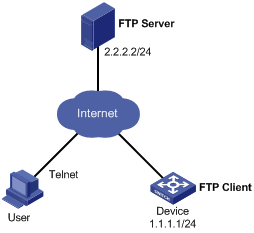
As shown in Figure 9, the current software version is soft-version1. The newest applications soft-version2.bin is saved in the aaa directory of the FTP server. The device and FTP server can reach each other, and the user and device can reach each other.
Immediately upgrade the software version of Device to soft-version2 through remote operations.
Upgrade procedure
1. Configure the FTP server (Configurations may vary with different types of servers)
# Enable FTP server.
<FTP-Server> system-view
[FTP-Server] ftp server enable
# Set the FTP username to aaa and password to hello.
[FTP-Server] local-user aaa
[FTP-Server-luser-aaa] password cipher hello
# Configure the user to have access to the aaa directory.
[FTP-Server-luser-aaa] service-type ftp
[FTP-Server-luser-aaa] authorization-attribute work-directory flash:/aaa
2. Configure the device
|
|
CAUTION: If the size of the Flash on the switch is not large enough, delete the original application programs from the Flash before downloading. |
# Before upgrade, execute the save command to save the current configuration. (Details not shown)
# Log in to the FTP server. (The prompt may vary with servers.)
<Device> ftp 2.2.2.2
Trying 2.2.2.2 ...
Press CTRL+K to abort
Connected to 2.2.2.2.
220 WFTPD 2.0 service (by Texas Imperial Software) ready for new user
User(2.2.2.2:(none)):aaa
331 Give me your password, please
Password:
230 Logged in successfully
[ftp]
# Download the soft-version2.bin program on FTP Server to the AMB.
[ftp] binary
[ftp] get soft-version2.bin
[ftp] bye
<Device>
# Specify the application program for the next boot on the AMB.
<Device> boot-loader file soft-version2.bin slot 0 main
# Copy the application program on the AMB to the SMB.
<Device> copy soft-version2.bin slot1#flash:/soft-version2.bin
# Specify the application program for the next boot on the SMB.
<Device> boot-loader file slot1#flash:/soft-version2.bin slot 1 main
# Reboot the device. The software version is upgraded now.
<Device> reboot
After the device reboot, you can verify the configuration with the display version command.
System software image upgrade example (IRF mode)
Network requirements
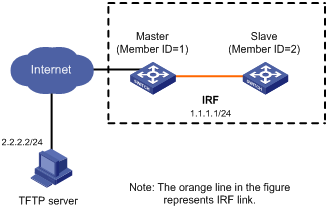
As shown in Figure 10, the IRF fabric comprises two member devices: Master has a member ID of 1 and Slave has a member ID of 2. The AMB of Master is in slot 0, and the SMB of Master is in slot 1. The AMB of Slave is in slot 0, and the SMB of Slave is in slot 1. The current software version is soft-version1 for the IRF fabric. The latest application soft-version2.bin and the latest configuration file new-config.cfg are both saved on the TFTP server. the TFTP server and the IRF fabric can reach each other.
Upgrade the software version of the IRF fabric to soft-version2 and configuration file to new-config.
Upgrade procedure
1. Configure the TFTP server (configurations may vary with different types of servers)
Obtain the system software image and configuration file through legitimate channels, such as the official website of H3C, agents, and technical staff. Save these files in the working path of the TFTP server for the access of the TFTP clients.
2. Configure the IRF member switches
# Download file new-config.cfg from the TFTP server to the AMB of Master (Note that configurations may vary with different types of servers).
<IRF> tftp 2.2.2.2 get new-config.cfg
..
File will be transferred in binary mode
Downloading file from remote TFTP server, please wait.....
TFTP: 917 bytes received in 1 second(s)
File downloaded successfully.
<IRF> copy new-config.cfg chassis1#slot1#flash:/new-config.cfg
# Download file new-config.cfg to the AMB of Slave.
<IRF> copy new-config.cfg chassis2#slot0#flash:/new-config.cfg
<IRF> copy new-config.cfg chassis2#slot1#flash:/new-config.cfg
# Download file soft-version2.bin from the TFTP server to Master and Slave.
<IRF> tftp 2.2.2.2 get soft-version2.bin
...
File will be transferred in binary mode
Downloading file from remote TFTP server, please wait............
TFTP: 10058752 bytes received in 141 second(s)
File downloaded successfully.
<IRF> copy soft-version2.bin chassis1#slot1#flash:/soft-version2.bin
<IRF> copy soft-version2.bin chassis2#slot0#flash:/soft-version2.bin
<IRF> copy soft-version2.bin chassis2#slot1#flash:/soft-version2.bin
# Specify file new-config.cfg as the system software image for the next boot of all member devices of the IRF fabric.
<IRF> startup saved-configuration flash:/new-config.cfg
Please wait ...
Setting the master board ...
... Done!
Setting the slave board ...
Chassis 1 Slot 1:
Set next configuration file successfully.
Chassis 2 Slot 0:
Set next configuration file successfully.
Chassis 2 Slot 1:
Set next configuration file successfully.
# Specify file soft-version2.bin as the system software image for the next boot of all main boards.
<IRF> boot-loader file flash:/soft-version2.bin chassis 1 slot 0 main
This command will set the boot file of the specified board. Continue? [Y/N]:y
The specified file will be used as the main boot file at the next reboot on chassis 1 slot 0!
<IRF> boot-loader file chassis1#slot1#flash:/soft-version2.bin chassis 1 slot 1 main
This command will set the boot file of the specified board. Continue? [Y/N]:y
The specified file will be used as the main boot file at the next reboot on chassis 1 slot 1!
<IRF> boot-loader file chassis2#slot0#flash:/soft-version2.bin chassis 2 slot 0 main
This command will set the boot file of the specified board. Continue? [Y/N]:y
The specified file will be used as the main boot file at the next reboot on chassis 2 slot 0!
<IRF> boot-loader file chassis2#slot1#flash:/soft-version2.bin chassis 2 slot 1 main
This command will set the boot file of the specified board. Continue? [Y/N]:y
The specified file will be used as the main boot file at the next reboot on chassis 2 slot 1!
# Reboot the device. The software version is upgraded now.
<IRF> reboot
To check if the upgrade is successful after the device reboots, use the display version command.
Scheduled upgrade configuration example
Network requirement
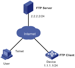
As shown in Figure 11, the current software version is soft-version1 for Device. The latest application soft-version2.bin is saved in the aaa directory of the FTP server. The device and the FTP server can reach each other, and the user and device can reach each other.
Upgrade the software version of Device to soft-version2 at a time when few services are processed (for example, at 1 am) through remote operations.
Configuration procedure
1. Configure the FTP server (configurations may vary with different types of servers)
# Enable the FTP server.
<FTP-Server> system-view
[FTP-Server] ftp server enable
# Set the FTP username to aaa and password to hello.
[FTP-Server] local-user aaa
[FTP-Server-luser-aaa] password cipher hello
# Set the user to have access to the flash:/aaa directory.
[FTP-Server-luser-aaa] service-type ftp
[FTP-Server-luser-aaa] work-directory flash:/aaa
Use text editor on the FTP server to edit batch file auto-update.txt. The following is the content of the batch file:
return
boot-loader file soft-version2.bin slot 0 main
boot-loader file slot1#flash:/soft-version2.bin slot 1 main
save
reboot
2. Configure Device
|
|
CAUTION: If the size of the flash on the switch is not large enough, delete the original application programs from the flash before downloading. |
# Before upgrade, execute the save command to save the current configuration. (Details not shown)
# Log in to FTP Server (The prompt may vary with servers.)
<Device> ftp 2.2.2.2
Trying 2.2.2.2 ...
Press CTRL+K to abort
Connected to 2.2.2.2.
220 WFTPD 2.0 service (by Texas Imperial Software) ready for new user
User(2.2.2.2:(none)):aaa
331 Give me your password, please
Password:
230 Logged in successfully
[ftp]
# Download file soft-version2.bin on the FTP server.
[ftp] binary
[ftp] get soft-version2.bin
[ftp] bye
<Device>
# Change the extension of file auto-update.txt to .bat.
<Device> rename auto-update.txt auto-update.bat
To ensure correctness of the file, use the more command to view the content of the file.
<Device> more flash:/auto-update.txt
return
boot-loader file soft-version2.bin slot 0 main
boot-loader file slot1#flash:/soft-version2.bin slot 1 main
save
reboot
# Specify file soft-version2.bin as the system software image to be used at the next boot of all main boards. Execute the scheduled automatic execution function to enable the device to be automatically upgraded at 1 am June 21st, 2010. (Slot number of the AMB is 0, and that of the SMB is 1)
<Device> copy soft-version2.bin slot1#flash:/soft-version2.bin
<Device> schedule job at 01:00 2010/6/21 view system execute auto-update.bat
To check if the upgrade is successful after the device reboots, use the display version command.
Hotfix configuration example
Network requirements
The software running on the device is of some problem. The patch file patch_mr.bin is saved in the aaa directory of the FTP server. the device and FTP server can reach each other, and the user and device can reach each other.
Hotfix the software on the device.
Figure 12 Network diagram
Configuration procedure
1. Configure the FTP server.
# Enable FTP server.
<FTP-Server> system-view
[FTP-Server] ftp server enable
# Configure an FTP user with the name aaa and password hello.
[FTP-Server] local-user aaa
[FTP-Server-luser-aaa] password cipher hello
# Assign read-write rights for the FTP user aaa.
[FTP-Server-luser-aaa] service-type ftp
[FTP-Server-luser-aaa] authorization-attribute work-directory flash:/aaa
2. Configure the device (FTP client).
|
|
CAUTION: Make sure the free flash space of the switch is large enough to store the patch file. |
# Before upgrading the software, use the save command to save the current system configuration. (Details not shown)
# Log in to FTP Server. The command output varies depending on server type.
<Device> ftp 2.2.2.2
Trying 2.2.2.2 ...
Press CTRL+K to abort
Connected to 2.2.2.2.
220 WFTPD 2.0 service (by Texas Imperial Software) ready for new user
User(2.2.2.2:(none)):aaa
331 Give me your password, please
Password:
230 Logged in successfully
[ftp]
# Download the file patch_mr.bin from FTP Server.
[ftp] binary
[ftp] get patch_mr.bin
[ftp] bye
<Device>
# Copy the patch file to the root directory of the SMB in slot 1.
<Device> copy patch_mr.bin slot1#flash:/
# Install the patch.
<Device> system-view
[Device] patch install flash:
Patches will be installed. Continue? [Y/N]:y
Do you want to continue running patches after reboot? [Y/N]:y
Installing patches........
Installation completed, and patches will continue to run after reboot.