| Title | Size | Downloads |
|---|---|---|
| 13-BFD Configuration.pdf | 306.75 KB |
- Table of Contents
- Related Documents
-
| Title | Size | Download |
|---|---|---|
| 13-BFD Configuration | 306.75 KB |
Table of Contents
Configuring BFD Basic Functions
Configuring Protocol-based BFD
Configuring BFD for Static Routes
Displaying and Maintaining BFD
Configuring BFD for the VRRP Backup to Monitor the Master
Configuring BFD for the VRRP Master to Monitor the Uplinks
Configuring BFD Echo Packet Mode for Static Routing
Configuring BFD Control Packet Mode for Static Routing
When configuring BFD, go to these sections for information you are interested in:
l Configuring BFD Basic Functions
l Configuring Protocol-based BFD
l Displaying and Maintaining BFD
![]()
l The term “router” or router icon in this document refers to a router in a generic sense or an Ethernet switch running routing protocols.
l An interface view mentioned in this chapter can be the view of an Ethernet port configured to operate in route mode. For how to switch the operating mode of an Ethernet port, refer to Ethernet Port Configuration in the Access Volume.
Introduction to BFD
Bidirectional forwarding detection (BFD) provides a single mechanism to quickly detect and monitor the connectivity of links in networks. To improve network performance, devices must quickly detect communication failures to restore communication through backup paths as soon as possible. Normally, devices in a network may employ the following detection methods:
l Detect link failures by sending hardware detection signals, such as SDH (synchronous digital hierarchy) transmission system alarms.
l If no hardware detection signals are provided or failures cannot be detected through hardware detection signals, devices can use the hello mechanism of a routing protocol for failure detection, which has a slower failure detection rate of more than one second. In Gigabit data transmission, such a rate will cause a large quantity of data to be dropped.
l Implement real-time detection for all media types and protocols through a uniform mechanism.
How BFD Works
BFD provides a general-purpose, standard, medium- and protocol-independent fast failure detection mechanism. It can uniformly and quickly detect the failures of the bidirectional forwarding paths between two routers for protocols, such as routing protocols.
BFD provides no neighbor discovery mechanism. Protocols that BFD services notify BFD of routers to which it needs to establish sessions. After a session is established, if no BFD control packet is received from the peer within the negotiated BFD interval, BFD notifies a failure to the protocol, which takes appropriate measures.
Operation of BFD
Figure 1-1 BFD session establishment
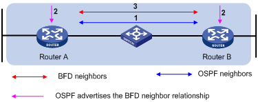
BFD session establishment (as shown in the above figure):
l A protocol sends Hello messages to discover neighbors and establish neighborships.
l After establishing neighborships, the protocol notifies BFD of the neighbor information, including destination and source addresses.
l BFD uses the information to establish BFD sessions.
Figure 1-2 BFD fault detection
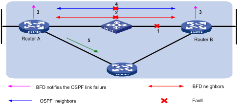
BFD fault detection (as shown in the above figure):
l Upon detection of a link failure, BFD clears the session and notifies the protocol of the failure.
l The protocol terminates the neighborship on the link.
l If a backup link is available, the protocol will use it to forward packets.
![]()
No detection time resolution is defined in the BFD draft. At present, most devices supporting BFD provide detection measured in milliseconds.
BFD session modes
l Control packet mode: Both ends of the link exchange BFD control packets to monitor link status.
l Echo mode: One end of the link sends Echo packets to the other end, which then forwards the packets back to the originating end, thereby monitoring link status in both directions.
BFD operating modes
Before a BFD session is established, there are two BFD operating modes: active and passive.
l Active mode: In this mode, BFD actively sends BFD control packets regardless of whether any BFD control packet is received from the peer.
l Passive mode: In this mode, BFD does not send control packets until a BFD control packet is received from the peer.
At least one end must operate in the active mode for a BFD session to be established.
After a BFD session is established, both ends must operate in one of the following two BFD operating modes: asynchronous and command.
l Asynchronous mode: A device operating in the asynchronous mode periodically sends BFD control packets. It tears down the BFD session if it receives no BFD control packet from the peer within the BFD interval.
l Demand mode: In this mode, it is assumed that a system has an independent way of verifying that it has connectivity to the other system. Once a BFD session is established, such a system may ask the other system to stop sending BFD Control packets, except when the system feels the need to verify connectivity explicitly, in which case a short sequence of BFD Control packets is exchanged, and then the far system quiesces. Demand mode may operate independently in each direction, or simultaneously.
![]()
l At present, only the asynchronous mode is supported.
l When a BFD session operates in Echo mode, the session is independent of the operating mode.
l When the connectivity to another system needs to be verified explicitly, a system sends several BFD control packets that have the Poll (P) bit set at the negotiated transmit interval. If no response is received within the detection interval, the session is considered down. If the connectivity is found to be up, no more BFD control packets are sent until the next command is issued.
Dynamic BFD parameter changes
Authentication modes
BFD provides the following authentication methods:
l Simple: Plain text authentication
l MD5: MD5 (Message Digest 5) authentication
l SHA1: SHA1 (Secure Hash Algorithm 1) authentication
BFD Packet Format
Figure 1-3 illustrates the BFD control packet format. BFD control packets are encapsulated into UDP packets with port number 3784.
Figure 1-3 BFD control packet format
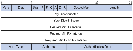
l Vers: Protocol version. The protocol version is 1.
l Diag: This bit indicates the reason for the last transition of the local protocol from up to some other state. Table 1-1 lists the states.
Table 1-1 Diag bit values
|
Diag |
Description |
|
0 |
No Diagnostic |
|
1 |
Control Detection Time Expired |
|
2 |
Echo Function Failed |
|
3 |
Neighbor Signaled Session Down |
|
4 |
Forwarding Pane Reset |
|
5 |
Path Down |
|
6 |
Concatenated Path Down |
|
7 |
Administratively Down |
|
8~31 |
Reserved for future use |
l State (Sta): Current BFD session state. Its value can be 0 for AdminDown, 1 for Down, 2 for Init, and 3 for Up.
l Demand (D): If set, Demand mode is active in the transmitting system (the system wishes to operate in Demand mode, knows that the session is up in both directions, and is directing the remote system to cease the periodic transmission of BFD Control packets). If clear, Demand mode is not active in the transmitting system.
l Poll (P): If set, the transmitting system is requesting verification of connectivity, or of a parameter change, and is expecting a packet with the Final (F) bit in reply. If clear, the transmitting system is not requesting verification.
l Final (F): If set, the transmitting system is responding to a received BFD Control packet that had the Poll (P) bit set. If clear, the transmitting system is not responding to a Poll.
l Control Plane Independent(C): If set, the transmitting system's BFD implementation does not share fate with its control plane (in other words, BFD is implemented in the forwarding plane and can continue to function through disruptions in the control plane.) If clear, the transmitting system's BFD implementation shares fate with its control plane.
l Authentication Present (A): If set, the Authentication Section is present and the session is to be authenticated.
l Reserved (R): This byte must be set to zero on transmit, and ignored on receipt.
l Detect Mult: Detection time multiplier.
l Length: Length of the BFD Control packet, in bytes.
l My Discriminator: A unique, nonzero discriminator value generated by the transmitting system, used to demultiplex multiple BFD sessions between the same pair of systems.
l Your Discriminator: It is the discriminator received from the corresponding remote system. This field reflects back the received value of My Discriminator, or is 0 if that value is unknown.
l Desired Min Tx Interval: This is the minimum interval, in microseconds, that the local system would like to use when transmitting BFD Control packets. The value zero is reserved.
l Required Min Rx Interval: This is the minimum interval, in microseconds, between received BFD Control packets that this system is capable of supporting. If this value is zero, the transmitting system does not want the remote system to send any periodic BFD Control packets.
l Required Min Echo Rx Interval: This is the minimum interval, in microseconds, between received BFD Echo packets that this system is capable of supporting. If this value is zero, the transmitting system does not support the receipt of BFD Echo packets.
l Auth Type: The authentication type in use, if the Authentication Present (A) bit is set.
Protocols and Standards
l draft-ietf-bfd-base-05: Protocol Independent Bidirectional Forwarding Detection
l draft-ietf-bfd-v4v6-1hop-05: BFD for IPv4 and IPv6 (Single Hop)
BFD Configuration Task List
Complete the following tasks to configure BFD:
|
Task |
Remarks |
|
|
Optional |
||
|
Required |
||
|
Required |
||
|
Required |
||
Configuring BFD Basic Functions
Configuration Prerequisites
Before configuring BFD detection modes, complete the following tasks:
l Configure the network layer addresses of the interfaces so that adjacent nodes are reachable to each other at the network layer;
l Configure the routing protocols that support BFD
Configuration Procedure
Follow these steps to configure BFD basic functions:
|
To do… |
Use the command… |
Remarks |
|
Enter system view |
system-view |
— |
|
Specify a BFD session initiation mode |
bfd session init-mode { active | passive } |
Optional active by default |
|
Enter interface view |
interface interface-type interface-number |
— |
|
Configure the minimum BFD transmit interval |
bfd min-transmit-interval value |
Optional The value range and default vary with devices. |
|
Configure the minimum echo receive interval |
bfd min-echo-receive-interval value |
Optional The value range and default vary with devices. |
|
Configure the minimum packet receive interval |
bfd min-receive-interval value |
Optional The value range and default vary with devices. |
|
Configure the detect time multiplier |
bfd detect-multiplier value |
Optional 5 by default |
|
Configure the authentication type |
bfd authentication-mode { md5 key-id key | sha1 key-id key | simple key-id password } |
Optional By default, the interface operates in the non-authentication mode. |
Configuring Protocol-based BFD
Configuring BFD for OSPF
Follow these steps to enable BFD on an OSPF interface:
|
To do… |
Use the command… |
Description |
|
Enter system view |
system-view |
— |
|
Enter interface view |
interface interface-type interface-number |
— |
|
Enable BFD on the interface |
ospf bfd enable |
Required Not enabled by default |
l One network segment can only belong to one area and you must specify each OSPF interface to belong to the specific area.
l Both ends of a BFD session must be on the same network segment and in the same area.
l For OSPF configuration, refer to OSPF Configuration in the IP Routing Volume.
Configuring BFD for VRRP
To configure BFD for VRRP, you need to configure a BFD track entry and then bind the track entry to a VRRP group.
Track starts and stops the BFD session. Upon detecting a neighbor failure, BFD notifies Track of the failure. Then, Track notifies it to VRRP for quick VRRP master/backup switchover.
Before associating a VRRP group with a track entry, you need to create the VRRP group on the interface and assign a virtual IP address to it.
Follow these steps to configure BFD for VRRP:
|
To do… |
Use the command… |
Remarks |
|
Enter system view |
system-view |
— |
|
Configure the source address of echo packets |
bfd echo-source-ip ip-address |
Required Not configured by default |
|
Configure a BFD track entry |
track track-entry-number bfd echo interface interface-type interface-number remote ip remote-ip local ip local-ip |
Required Not configured by default |
|
Enter interface view |
interface interface-type interface-number |
— |
|
Bind a VRRP group with the Track entry |
vrrp vrid virtual-router-id track track-entry-number { switchover | [ reduced priority-reduced ] } |
Required By default, no monitored interface is specified. |
![]()
l The local-ip of the track entry must be the IP address of the specified outgoing interface and must be on the network segment as the remote-ip.
l For VRRP configuration, refer to VRRP Configuration in the System Volume.
l For Track configuration, refer to Track Configuration in the System Volume.
Configuring BFD for Static Routes
A dynamic routing protocol notifies BFD of its neighbor information. BFD uses such information to establish sessions with neighbors by sending BFD control packets. Static routing, which has no neighbor discovery mechanism, implements BFD as follows:
BFD control packet mode
To use BFD control packets for bidirectional detection between two devices, you need to enable BFD control packet mode for each device’s static route destined to the peer.
Follow these steps to configure BFD control packet mode for static routes:
|
To do… |
Use the command… |
Remarks |
|
Enter system view |
system-view |
— |
|
Enable BFD control packet mode for static routes |
ip route-static dest-address { mask | mask-length } interface-type interface-number next-hop-address bfd control-packet [ preference preference-value ] [ tag tag-value ] [ description description-text ] |
Use either command |
|
ip route-static vpn-instance s-vpn-instance-name&<1-6> dest-address { mask | mask-length } interface-type interface-number next-hop-address bfd control-packet [ preference preference-value ] [ tag tag-value ] [ description description-text ] |
BFD echo packet mode
With BFD echo packet mode enabled for a static route, the local device sends BFD echo packets to the peer, which loops it back to test the link in between.
Follow these steps to configure BFD echo packet mode for static routes:
|
To do… |
Use the command… |
Remarks |
|
Enter system view |
system-view |
— |
|
Configure the source address of echo packets |
bfd echo-source-ip ip-address |
Required Not configured by default |
|
Enable BFD echo packet mode for static routes |
ip route-static dest-address { mask | mask-length } interface-type interface-number next-hop-address bfd echo-packet [ preference preference-value ] [ tag tag-value ] [ description description-text ] |
Use either command |
|
ip route-static vpn-instance s-vpn-instance-name&<1-6> dest-address { mask | mask-length } interface-type interface-number next-hop-address bfd echo-packet [ preference preference-value ] [ tag tag-value ] [ description description-text ] |
![]()
l If route flaps occur, enabling BFD may worsen the route flaps. Therefore, enable BFD with care in such cases.
l The source address of echo packets must be configured if the BFD session operates in the echo mode.
l If you configure BFD for a static route, you need to specify the outbound interface and next hop IP address for the route.
l BFD cannot be used for a static route with the outbound interface having the spoofing attribute.
l BFD can be used for static routes with direct nexthops rather than non-direct nexthops.
l In the draft, the BFD echo function is revised to specify that a BFD session is established at only one end when the echo mode is used.
l For static route configuration, refer to Static Routing Configuration in the IP Routing Volume.
Enabling Trap
When the trap function is enabled on the BFD module, the module will generate trap messages at the notifications level to report the important events of the module. The generated trap messages are sent to the device's information center, which determines the output rules for the trap messages, namely, whether to output the trap messages and the output destinations). For the information center configuration, refer to Information Center Configuration in the System Volume.
Follow these steps to enable BFD trap:
|
To do… |
Use the command… |
Remarks |
|
Enter system view |
system-view |
— |
|
Enable BFD trap |
snmp-agent trap enable bfd |
Optional Enabled by default |
![]()
For the description of the snmp-agent trap enable bfd command, refer to the snmp-agent trap enable command in SNMP Commands in the System Volume.
Displaying and Maintaining BFD
|
To do… |
Use the command… |
Remarks |
|
Display information about BFD-enabled interfaces |
display bfd interface [ verbose ] |
Available in any view |
|
Display information about enabled BFD debugging |
display bfd debugging-switches |
Available in any view |
|
Display PAF configuration information |
display bfd paf |
Available in any view |
|
Display BFD session information |
display bfd session [ verbose ] |
Available in any view |
|
Clear BFD session statistics |
reset bfd session statistics |
Available in user view |
BFD Configuration Examples
Configuring BFD for OSPF
Network requirements
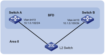
l Switch A and Switch B are interconnected through a Layer 2 switch. BFD is enabled on the switch interfaces. OSPF is enabled on the switches that are reachable to each other at the network layer.
l When the link between Switch A and the Layer 2 switch fails, BFD can quickly detect the failure and notify OSPF of the failure.
Figure 1-4 Network diagram for BFD configuration on an OSPF link
Configuration procedure
1) Configure the ip address of the interfaces (omitted).
2) Configure OSPF basic functions.
# Configure Switch A.
[SwitchA] ospf
[SwitchA-ospf-1] area 0
[SwitchA-ospf-1-area-0.0.0.0] network 10.1.0.0 0.0.0.255
[SwitchA-ospf-1-area-0.0.0.0] quit
[SwitchA-ospf-1] quit
[SwitchA] interface vlan 10
[SwitchA-Vlan-interface10] ospf bfd enable
[SwitchA-Vlan-interface10] quit
# Configure Switch B.
[SwitchB] ospf
[SwitchB-ospf-1] area 0
[SwitchB-ospf-1-area-0.0.0.0] network 10.1.0.0 0.0.0.255
[SwitchB-ospf-1-area-0.0.0.0] quit
[SwitchB-ospf-1] quit
[SwitchB] interface vlan-interface 10
[SwitchB-Vlan-interface10] ospf bfd enable
[SwitchB-Vlan-interface10] quit
3) Configure BFD parameters.
# Configure Switch A.
[SwitchA] bfd session init-mode active
[SwitchA] interface vlan-interface 10
[SwitchA-Vlan-interface10] bfd min-transmit-interval 500
[SwitchA-Vlan-interface10] bfd min-receive-interval 500
[SwitchA-Vlan-interface10] bfd detect-multiplier 7
[SwitchA-Vlan-interface10] bfd authentication-mode simple 1 zhang
[SwitchA-Vlan-interface10] quit
[SwitchA] quit
# Configure Switch B.
[SwitchB] bfd session init-mode active
[SwitchB] interface vlan-interface 10
[SwitchB-Vlan-interface10] bfd min-transmit-interval 500
[SwitchB-Vlan-interface10] bfd min-receive-interval 500
[SwitchB-Vlan-interface10] bfd detect-multiplier 6
[SwitchB-Vlan-interface10] bfd authentication-mode simple 1 zhang
4) Verify the configuration.
# Enable BFD debugging on Switch A.
<SwitchA> debugging bfd scm
<SwitchA> debugging bfd event
<SwitchA> debugging ospf event
<SwitchA> terminal debugging
# When the link between Switch A and the Layer 2 switch fails, you can see that Switch A can quickly detect the changes on Switch B.
%Nov 12 18:34:48:823 2005 SwitchA BFD/5/LOG: Sess[10.1.0.102/10.1.0.100, vlan10], Sta : UP->DOWN, Diag: 1
%Nov 12 18:34:48:824 2005 SwitchA RM/4/RMLOG:OSPF-NBRCHANGE: Process 1, Neighbour 10.1.0.102 (vlan10) from Full to Down
*0.50673825 SwitchA BFD/8/SCM:Sess[10.1.0.102/10.1.0.100, vlan10],Oper: Reset
*0.50673825 SwitchA BFD/8/EVENT:Send sess-down Msg, [Src:10.1.0.102, Dst:10.1.0.100, vlan10] Protocol: OSPF
*0.50673826 SwitchA RM/7/RMDEBUG:OSPF-BFD: Message Type rcv BFD down, Connect Type direct-connect, Src IP Address 10.1.0.102, Src IFIndex 5, Dst IP Address 10.1.0.100
*0.50673827 SwitchA RM/7/RMDEBUG:OSPF-BFD: Message Type delete session, Connect Type direct-connect, Src IP Address 10.1.0.102, Src IFIndex 5, Dst IP Address 10.1.0.100
OSPF 1: Nbr 10.1.0.100 Rcv KillNbr State Full -> Down.
*0.50673829 SwitchA BFD/8/EVENT:Receive Delete-sess, [Src:10.1.0.102, Dst:10.1.0.100, vlan10], Direct, Proto:OSPF
*0.50673830 SwitchA BFD/8/SCM:Sess[10.1.0.102/10.1.0.100, vlan10], Oper: Del application(OSPF)
*0.50673831 SwitchA BFD/8/SCM:No application in session, delete session[10.1.0.102/10.1.0.100, vlan10]
*0.50673831 SwitchA BFD/8/SCM:Sess[10.1.0.102/10.1.0.100, vlan10], Oper: Delete
*0.50673832 SwitchA BFD/8/SCM:Delete send-packet timer
*0.50673833 SwitchA BFD/8/SCM:Delete session entry
*0.50673833 SwitchA BFD/8/SCM:Delete session from IP hash table
*0.50673834 SwitchA BFD/8/SCM:Delete session from bfd interface
*0.50673834 SwitchA BFD/8/SCM:No session under bfd-int[vlan10] with default configuration, delete bfd-if
*0.50673835 SwitchA BFD/8/SCM:Bfd-if[vlan10], Oper: Delete
*0.50673840 SwitchA BFD/8/SCM:No bfd session exists, stop receiving any bfd packets
# Display detailed OSPF neighbor information of Switch A. You can see that Switch A has removed its neighbor relationship with Switch B.
<SwitchA> display ospf peer verbose
Last Neighbor Down Event:
Router ID: 10.1.0.100
Local Address: 10.1.0.102
Remote Address: 10.1.0.100
Time: Jul 12 14:28:52 2006
Reason: BFD session down
Configuring BFD for the VRRP Backup to Monitor the Master
Network requirements
If BFD is not configured, when the master in a VRRP group fails, the backup cannot become the master until the configured timeout timer expires. The timeout is generally three to four seconds and therefore the switchover is slow. To solve this problem, VRRP uses BFD to probe the state of the master. Once the master fails, the backup can become the new master quickly.
Figure 1-5 Network diagram for monitoring the master on the backup

Configuration procedure
# Configure Switch A.
<SwitchA> system-view
[SwitchA] vlan 2
[SwitchA–vlan2] port ethernet 1/0/1
[SwitchA–vlan2] quit
[SwitchA] interface vlan-interface 2
[SwitchA–vlan-interface2] ip address 192.168.0.101 24
[SwitchA–vlan-interface2] vrrp vrid 1 virtual-ip 192.168.0.10
[SwitchA–vlan-interface2] vrrp vrid 1 priority 110
[SwitchA–vlan-interface2] return
# Configure Switch B.
<SwitchB> system-view
[SwitchB] bfd session init-mode active
[SwitchB] bfd echo-source-ip 10.10.10.10
[SwitchB] vlan 2
[SwitchB–vlan2] port ethernet 1/0/1
[SwitchB–vlan2] quit
[SwitchB] interface vlan-interface 2
[SwitchB–vlan-interface2] ip address 192.168.0.102 24
[SwitchB–vlan-interface2] bfd min-echo-receive-interval 500
[SwitchB–vlan-interface2] bfd detect-multiplier 3
[SwitchB–vlan-interface2] quit
[SwitchB] track 1 bfd echo interface vlan-interface 2 remote ip 192.168.0.101 local ip 192.168.0.102
[SwitchB] interface vlan-interface 2
[SwitchB–vlan-interface2] vrrp vrid 1 virtual-ip 192.168.0.10
[SwitchB–vlan-interface2] vrrp vrid 1 track 1 switchover
[SwitchB–vlan-interface2] return
Use the display vrrp verbose command to display the configuration.
# Display the detailed information of VRRP group 1 on Switch A.
<SwitchA> display vrrp verbose
IPv4 Standby Information:
Run Method : VIRTUAL-MAC
Interface : vlan-interface2
VRID : 1 Adver. Timer : 1
Admin Status : UP State : Master
Config Pri : 110 Run Pri : 110
Preempt Mode : YES Delay Time : 0
Auth Type : NONE
Virtual IP : 192.168.0.10
Virtual MAC : 0000-5e00-0101
Master IP : 192.168.0.101
# Display the detailed information of VRRP group 1 on Switch B.
<SwitchB> display vrrp verbose
IPv4 Standby Information:
Run Method : VIRTUAL-MAC
Total number of virtual routers: 1
Interface : vlan-interface2
VRID : 1 Adver. Timer : 1
Admin Status : UP State : Backup
Config Pri : 100 Run Pri : 100
Preempt Mode : YES Delay Time : 0
Auth Type : NONE
Track Object : 1 Switchover
Virtual IP : 192.168.0.10
Master IP : 192.168.0.101
The display above shows that, in backup group 1, Switch A is the master router and Switch B the backup router.
# When Switch A goes down, use the display vrrp command to display the detailed information of VRRP group 1 on Switch B.
<SwitchB> display vrrp verbose
IPv4 Standby Information:
Run Method : VIRTUAL-MAC
Total number of virtual routers: 1
Interface : vlan-interface2
VRID : 1 Adver. Timer : 1
Admin Status : UP State : Master
Config Pri : 100 Run Pri : 100
Preempt Mode : YES Delay Time : 0
Auth Type : NONE
Track Object : 1 Switchover
Virtual IP : 192.168.0.10
Virtual MAC : 0000-5e00-0101
Master IP : 192.168.0.102
# Display the track entry information of Switch B.
<SwitchB> display track 1
Track ID: 1
Status: Negative
Reference Object:
BFD Session:
Packet type: Echo
Interface : vlan-interface2
Remote IP : 192.168.0.101
Local IP : 192.168.0.102
Configuring BFD for the VRRP Master to Monitor the Uplinks
Network requirements
The master monitors the state of its uplink. When the uplink is down, the mater decreases its priority and sends a VRRP packet with the new priority. Upon receiving the packet with a lower priority, the backup becomes the new master after a very short delay.
Figure 1-6 Network diagram for monitoring the uplink through VRRP
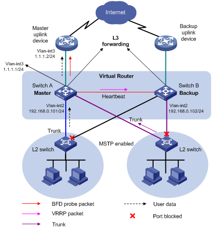
Configuration procedure
# Configure Switch A. The IP address of the uplink device is 1.1.1.2/24.
<SwitchA> system-view
[SwitchA] bfd session init-mode active
[SwitchA] bfd echo-source-ip 10.10.10.10
[SwitchA] vlan 3
[SwitchA–vlan3] port ethernet 1/0/1
[SwitchA–vlan3] quit
[SwitchA] interface vlan-interface 3
[SwitchA–vlan-interface3] ip address 1.1.1.1 24
[SwitchA–vlan-interface3] bfd min-echo-receive-interval 500
[SwitchA–vlan-interface3] bfd detect-multiplier 3
[SwitchA–vlan-interface3] quit
[SwitchA] track 1 bfd echo interface vlan-interface 3 remote ip 1.1.1.2 local ip 1.1.1.1
[SwitchA] vlan 2
[SwitchA–vlan2] port ethernet 1/0/2
[SwitchA–vlan2] quit
[SwitchA] interface vlan-interface 2
[SwitchA–vlan-interface3] ip address 192.168.0.101 24
[SwitchA–vlan-interface2] vrrp vrid 1 virtual-ip 192.168.0.10
[SwitchA–vlan-interface2] vrrp vrid 1 priority 110
[SwitchA–vlan-interface2] vrrp vrid 1 track 1 reduced 20
[SwitchA–vlan-interface2] return
# Configure Switch B.
<SwitchB> system-view
[SwitchB] vlan 2
[SwitchB–vlan2] port ethernet 1/0/1
[SwitchB–vlan2] quit
[SwitchB] interface vlan-interface 2
[SwitchB–vlan-interface2] ip address 192.168.0.102 24
[SwitchB–vlan-interface2] vrrp vrid 1 virtual-ip 192.168.0.10
[SwitchB–vlan-interface2] return
Use the display vrrp verbose command to display the configuration.
# Display the detailed information of VRRP group 1 on Switch A.
<SwitchA> display vrrp verbose
IPv4 Standby Information:
Run Method : VIRTUAL-MAC
Total number of virtual routers: 1
Interface : vlan-interface2
VRID : 1 Adver. Timer : 1
Admin Status : UP State : Master
Config Pri : 110 Run Pri : 110
Preempt Mode : YES Delay Time : 0
Auth Type : NONE
Track Object : 1 Pri Reduced : 20
Virtual IP : 192.168.0.10
Virtual MAC : 0000-5e00-0101
Master IP : 192.168.0.101
# Display the detailed information of VRRP group 1 on Switch B.
<SwitchB> display vrrp verbose
IPv4 Standby Information:
Run Method : VIRTUAL-MAC
Total number of virtual routers: 1
Interface : vlan-interface2
VRID : 1 Adver. Timer : 1
Admin Status : UP State : Backup
Config Pri : 100 Run Pri : 100
Preempt Mode : YES Delay Time : 0
Auth Type : NONE
Virtual IP : 192.168.0.10
Master IP : 192.168.0.101
The display above shows that, in VRRP group 1, Switch A is the master router and Switch B the backup router.
# When the uplink of Switch A goes down, use the display vrrp command to display the detailed information of VRRP group 1 on Switch A.
<SwitchA> display vrrp verbose
IPv4 Standby Information:
Run Method : VIRTUAL-MAC
Interface : vlan-interface2
VRID : 1 Adver. Timer : 1
Admin Status : UP State : Backup
Config Pri : 110 Run Pri : 90
Preempt Mode : YES Delay Time : 0
Auth Type : NONE
Track Object : 1 Pri Reduced : 20
Virtual IP : 192.168.0.10
Master IP : 192.168.0.102
# When the uplink of Switch A goes down, display the detailed information of VRRP group 1 on Switch B.
<SwitchB> display vrrp verbose
IPv4 Standby Information:
Run Method : VIRTUAL-MAC
Total number of virtual routers: 1
Interface : vlan-interface2
VRID : 1 Adver. Timer : 1
Admin Status : UP State : Master
Config Pri : 100 Run Pri : 100
Preempt Mode : YES Delay Time : 0
Auth Type : NONE
Virtual IP : 192.168.0.10
Virtual MAC : 0000-5e00-0101
Master IP : 192.168.0.102
# Display the track entry information of Switch A.
<SwitchA> display track 1
Track ID: 1
Status: Negative
Reference Object:
BFD Session:
Packet type: Echo
Interface : vlan-interface3
Remote IP : 1.1.1.2
Local IP : 1.1.1.1
Configuring BFD Echo Packet Mode for Static Routing
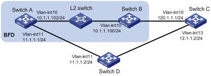
Network requirements
Configure a static route on Switch A to Switch C and enable BFD. When the link between Switch A and Switch B fails, Switch A selects Switch D to reach Switch C.
Figure 1-7 Network diagram for BFD configuration on a static route
Configuration procedure
1) # Configure IP addresses for interfaces (omitted).
2) Configure BFD
# Configure a static route on Switch A and enable BFD on it. Implement BFD through BFD echo packets.
<SwitchA> system-view
[SwitchA] bfd echo-source-ip 123.1.1.1
[SwitchA] interface vlan-interface 10
[SwitchA-vlan-interface10] bfd min-echo-receive-interval 500
[SwitchA-vlan-interface10] bfd detect-multiplier 7
[SwitchA-vlan-interface10] quit
[SwitchA] ip route-static 120.1.1.1 24 vlan-interface 10 10.1.1.100 bfd echo-packet
[SwitchA] ip route-static 120.1.1.1 24 vlan-interface 11 11.1.1.2 preference 65
[SwitchA] quit
3) Verify the configuration
# Display BFD session information on Switch A.
<SwitchA> display bfd session
Total Session Num: 1 Init Mode: Active
Session Working Under Echo Mode:
LD SourceAddr DestAddr State Holdtime Interface
7 10.1.1.102 10.1.1.100 Up 1700ms Vlan10
# Display static route information on Switch A.
<SwitchA> display ip routing-table protocol static
Public Routing Table : Static
Summary Count : 2
Static Routing table Status : <Active>
Summary Count : 1
Destination/Mask Proto Pre Cost NextHop Interface
120.1.1.1/24 Static 65 0 10.1.1.100 Vlan10
Direct Routing table Status : <Inactive>
Summary Count : 1
Destination/Mask Proto Pre Cost NextHop Interface
120.1.1.1/24 Static 60 0 11.1.1.2 Vlan11
# Enable BFD debugging on Switch A.
<SwitchA> debugging bfd event
<SwitchA> debugging bfd scm
<SwitchA> terminal debugging
# When the link between Switch B and the Layer-2 switch goes down, Switch A can quickly detect the changes on Switch B.
%Nov 12 19:28:28:592 2005 SwitchA BFD/5/LOG:Sess[123.1.1.1/10.1.1.100, Vlan10], Sta: UP->DOWN, Diag: 1
*0.53892593 SwitchA BFD/8/SCM:Sess[123.1.1.1/10.1.1.100, Vlan10], Oper: Reset
*0.53892593 SwitchA BFD/8/EVENT:Send sess-down Msg, [Src:123.1.1.1, Dst:10.1.1.100, Vlan10] Protocol: STATIC
*0.53892595 SwitchA RM/7/LOG:static route [Dest:120.1.1.1/24,Nexthop:10.1.1.100,ExitIf: Vlan10] became invalid
# Execute the display ip routing-table protocol static command, and you can see Switch A selects Switch D to reach Switch C.
<SwitchA> display ip routing-table protocol static
Public Routing Table : Static
Summary Count : 2
Static Routing table Status : < Active>
Summary Count : 1
Destination/Mask Proto Pre Cost NextHop Interface
120.1.1.1/24 Static 65 0 11.1.1.2 Vlan11
Static Routing table Status : < Inactive>
Summary Count : 1
Destination/Mask Proto Pre Cost NextHop Interface
120.1.1.1/24 Static 60 0 10.1.1.100 Vlan10
Configuring BFD Control Packet Mode for Static Routing
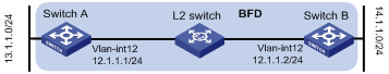
Network requirements
Configure a static route to subnet 14.1.1.0/24 on Switch A and configure a static route to subnet 13.1.1.0/24 on Switch B. Both routes have BFD control packet mode enabled. When the link between Switch A and Switch B fails, BFD can detect it immediately.
Figure 1-8 Configure BFD control packet mode for static routing
Configuration procedure
1) Configure BFD
# Configure Switch A.
<SwitchA> system-view
[SwitchA] interface vlan-interface12
[SwitchA-vlan-interface12] ip address 12.1.1.1 24
[SwitchA-vlan-interface12] bfd min-transmit-interval 500
[SwitchA-vlan-interface12] bfd min-receive-interval 500
[SwitchA-vlan-interface12] bfd detect-multiplier 9
[SwitchA-vlan-interface12] quit
[SwitchA] ip route-static 14.1.1.0 24 vlan-interface 12 12.1.1.2 bfd control-packet
[SwitchA] quit
# Configure Switch B.
<SwitchB> system-view
[SwitchB] interface vlan-interface12
[SwitchB-vlan-interface12] ip address 12.1.1.2 24
[SwitchB-vlan-interface12] bfd min-transmit-interval 500
[SwitchB-vlan-interface12] bfd min-receive-interval 500
[SwitchB-vlan-interface12] bfd detect-multiplier 9
[SwitchB-vlan-interface12]] quit
[SwitchB] ip route-static 13.1.1.0 24 vlan-interface 12 12.1.1.1 bfd control-packet
[SwitchB] quit
2) Verify the configuration.
<SwitchA> display bfd session
Total Session Num: 1 Init Mode: Active
Session Working Under Ctrl Mode:
LD/RD SourceAddr DestAddr State Holdtime Interface
4/7 12.1.1.1 12.1.1.2 Up 2000ms Vlan12
# Display the static route information of Switch A.
<SwitchA> display ip routing-table protocol static
Public Routing Table : Static
Summary Count : 1
Static Routing table Status : < Active>
Summary Count : 1
Destination/Mask Proto Pre Cost NextHop Interface
14.1.1.0/24 Static 60 0 12.1.1.2 Vlan12
Static Routing table Status : < Inactive>
Summary Count : 0
# Enable BFD debugging on Switch A.
<SwitchA> debugging bfd event
<SwitchA> debugging bfd scm
<SwitchA> terminal debugging
# When the link between Switch A and Layer-2 switch fails, Switch A can detect the failure.
%Jul 27 10:18:18:672 2007 SwitchA BFD/4/LOG:Sess[12.1.1.1/12.1.1.2, Vlan12,Ctrl],
Sta: UP->DOWN, Diag: 1
*Jul 27 10:18:18:672 2007 SwitchA BFD/7/EVENT:Send sess-down Msg, [Src:12.1.1.1,
Dst:12.1.1.2, Vlan12,Ctrl], instance:0, protocol:STATIC
*Jul 27 10:18:19:172 2007 SwitchA BFD/7/EVENT:Receive Delete-sess, [Src:12.1.1.1
,Dst:12.1.1.2, Vlan12,Ctrl], Direct, Instance:0x0, Proto:STATIC
*Jul 27 10:18:19:172 2007 SwitchA BFD/7/EVENT:Notify driver to stop receiving bf
# Display the inactive static route information on Switch A.
<SwitchA> display ip routing-table protocol static
Public Routing Table : Static
Summary Count : 1
Static Routing table Status : < Active>
Summary Count : 0
Static Routing table Status : < Inactive>
Summary Count : 1
Destination/Mask Proto Pre Cost NextHop Interface
14.1.1.0/24 Static 60 0 12.1.1.2 Vlan12
