- Table of Contents
-
- H3C S9500 Operation Manual-Release1648[v1.24]-07 Security Volume
- 00-1Cover
- 01-Protocol Port Security Configuration
- 02-802.1x Configuration
- 03-AAA RADIUS HWTACACS Configuration
- 04-Password Control Configuration
- 05-SSH Configuration
- 06-IDS Linkage Configuration
- 07-Portal Configuration
- 08-VBAS Configuration
- 09-Traffic Accounting Configuration
- Related Documents
-
| Title | Size | Download |
|---|---|---|
| 07-Portal Configuration | 258.11 KB |
Table of Contents
Chapter 1 Portal Configuration
1.1.2 Introduction to Extended Portal Functions
1.1.4 Portal Authentication Procedure
1.1.5 Running Methods of Portal
1.1.6 Portal Authentication-free Users and Free IP Addresses
1.1.7 ARP Packet Handshake between the User PC and the Switch
1.1.8 Portal Rate Limit Function
1.2 Basic Portal Configuration
1.2.1 Configuration Prerequisites
1.2.3 Portal Direct Authentication Method Configuration Example
1.2.4 Portal ReDHCP Authentication Method Configuration Example
1.2.5 Layer 3 Portal Authentication Method Configuration Example
1.2.6 Configuring Direct Portal Authentication with Extended Functions
1.2.7 Configuring Re-DHCP Portal Authentication with Extended Functions
1.2.8 Configuring Layer 3 Portal Authentication with Extended Functions
1.3 Portal Authentication-free User and Free IP Address Configuration
1.3.1 Configuration Prerequisites
1.3.3 Authentication-free User and Free IP Address Configuration Example
1.4 Portal Rate Limit Function Configuration
1.4.2 Portal Rate Limit Function Configuration Example
1.5.1 Portal User Deletion Procedure
Chapter 1 Portal Configuration
When configuring portal, go to these sections for information you are interested in:
l Portal Authentication-free User and Free IP Address Configuration
l Portal Rate Limit Function Configuration
1.1 Portal Overview
1.1.1 Introduction
Portal is also known as portal website, and Portal authentication is also known as the Web authentication. Its major advantages are:
l Users need not install any client software;
l It is powerful in its ability to support new services. With the help of Portal authentication, the operators can provide services such as information query, online shopping based on Portal.
The principle of Portal is: Unauthenticated users can access only specified website servers, and any other access is redirected to the Portal server unconditionally. Users can access the Internet only after they are successfully authenticated.
1.1.2 Introduction to Extended Portal Functions
By forcing users to implement patching and anti-virus policies, extended portal functions help users to defend against viruses. The main extended functions are described as follows:
l Security authentication mechanism: The security authentication mechanism works after the identity authentication process to check whether the required anti-virus software is installed on the terminal of a user, whether the terminal is installed with unauthorized software, and whether the terminal has the updated virus definition and operating system patches.
l Resource access restriction: A user passing identity authentication can access only network resources like the anti-virus server or OS patch server, which are called the restricted resources. Only users passing security authentication can access more network resources, which are called the unrestricted resources.
1.1.3 Portal Structure
The basic network diagram of Portal is shown in Figure 1-1. It is composed of four elements: authentication client, access device, Portal server, and authentication/accounting server.
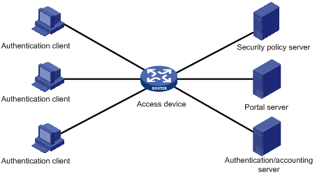
l Authentication client is the Internet Web Browser where the HTTP/HTTPS protocols run. All the HTTP requests are submitted to the Portal server before the user passes the authentication.
l Access device unconditionally forces the HTTP requests of authentication client to the Portal server before the user passes the authentication. The access device interacts with the authentication/accounting server to implement the authentication and accounting function. Access devices refer to H3C S9500 series switches in this book.
l Portal server is a Web server. Users can access it by using standard WWW browsers. The portal server provides free portal service and Web-authentication-based interface. The access device exchanges the authentication information of the authentication client with the Portal server. Internet content provider (ICP) can provide related information about its own website to users through this website.
l Authentication/accounting server implements the authentication and accounting function for the users. The access device interacts with the authentication/accounting server through the RADIUS protocol.
l Security policy server interacts with the portal client and the access device for security authentication and resource authorization.
![]() Caution:
Caution:
l To use the Portal service, network address translation (NAT) devices cannot exist among authentication clients, access devices, Portal servers and authentication/accounting servers.
l The operating mode of the port where the online user resides cannot be changed.
l Do not change the port (on the switch) connecting to the Portal users freely. The online users of the original port will be inactive for some time (defaults to 5 minutes) before they are active in the new port.
1.1.4 Portal Authentication Procedure
Portal authentication procedure on H3C series switches is:
l When the switch receives the login user's HTTP packets for the first time, it will judge whether this user is a Portal user at first. For Portal users, the switch allows the users to access only the contents of the specified website servers (the Portal server and the authentication-free addresses).
l For the HTTP packets of the Portal user to access other websites, the switch will redirect them to the Portal server in the way of TCP cheat.
l The Portal server provides a Web interface for the user to input username and password. The input username and password are forwarded to the switch through the Portal server.
l The switch sends the username and password to the authentication server for authentication. The switch allows the user to access Internet only after the user passes the authentication, and then the switch will not redirect HTTP packets of this user.
l After the user passes the authentication, the switch checks whether there is any security policy for the user. If not, it allows the user to access the Internet. Otherwise, the client, the switch, and the security policy server communicate to perform security authentication of the user, and the security policy server authorizes the user to access resources depending on the security authentication result. If the user passes the security authentication, the user can access the unrestricted resources, and if the user fails the security authentication, the user can access only the restricted resources.
![]() Caution:
Caution:
You cannot enable both Portal and 802.1x on the same switch.
1.1.5 Running Methods of Portal
In H3C series switches, Portal runs in one of the following three methods: Direct authentication method, ReDHCP authentication method and Layer 3 authentication method.
l Direct authentication method: In this method, the user gets a public address directly. Before passing authentication, the user can access only the Portal server and the set authentication-free addresses. The user can access Internet after passing authentication.
l ReDHCP authentication method: In this method, the user gets a private address through DHCP before passing authentication. Before passing authentication, the user can access only the Portal server and the set authentication-free addresses. The user can apply for a public address and access Internet after passing authentication.
l Layer 3 Portal authentication method: This method expands the Direct authentication method. In this method, the user can access the Portal-enabled switch across network segments.
& Note:
l Considering security problems, both the Direct authentication method and the ReDHCP authentication method require checking MAC addresses of the user. So Portal can be enabled only on the first Layer 3 interface that the user accesses. That is to say, Layer-3-protocol-enabled network devices cannot exist between the user and the access devices.
l The Layer 3 Portal authentication method does not check MAC addresses of the user, so the security performance is reduced. You are not recommended to use the Layer 3 Portal authentication method in occasions requiring high security performance.
1.1.6 Portal Authentication-free Users and Free IP Addresses
I. Authentication-free users
Authentication-free users are users that can access Internet without Portal authentication. In the network practice, you can configure network devices attached to the switch or several servers as authentication-free users, so that they can access Internet without authentication.
The information about authentication-free users includes IP addresses, MAC addresses, and the connected switch ports and VLANs. Only the users who match all the information can access Internet without authentication.
II. Free IP addresses
Free IP addresses are IP addresses that the user can access unrestrictedly. Free IP addresses can be the IP addresses of DNS servers or the IP addresses that ISP provides to access free websites. All users can access these free IP addresses unrestrictedly.
![]() Caution:
Caution:
Authentication-free users have the same priority as the authentication users. ACLs are applied according to the applying order. First delivered packets are validated first. You need to avoid the conflict with authentication users in the configuration.
1.1.7 ARP Packet Handshake between the User PC and the Switch
When authentications are performed in the Direct method or ReDHCP method, the switch handshakes with the user PC through ARP packets after the user has passed Portal authentication. If the switch finds the handshake abnormal, it will cut the connection with the user actively and notice the Portal server about this case.
![]() Caution:
Caution:
l When a Portal user is online, you cannot enable the DHCP security feature.
l To enable the DHCP security feature, you must enable it when configuring Portal.
1.1.8 Portal Rate Limit Function
The Portal rate limit function is used together with the bandwidth limit service that the CAMS server provides. The bandwidth limit service is that you can specify the bandwidth for each user when you are configuring the service for each user on the CAMS server.
The principle of Portal rate limit is as follows: when the switch receives the bandwidth limit rules for Portal users from the CAMS server, the switch will limit the traffic on the specified upload interface, that is to say, the switch will perform bandwidth control for the upload rates of Portal users.
& Note:
l An upload interface is the interface to connect the switch with the upstream network devices.
l The system supports only one upload interface for rate limit.
1.2 Basic Portal Configuration
1.2.1 Configuration Prerequisites
l A valid IP address has been configured for this portal-enabled VLAN interface.
l 802.1x is not enabled on the switch.
l The Portal server has been installed and configured. Refer to CAMS Portal Service Component User Manual for details about installation and configuration.
l To implement extended portal functions, you need to install and configure the security policy server. For how to install and configure the security policy server, refer to CAMS Portal Service Component User Manual.
& Note:
l Refer to DHCP Configuration in the IP Services Volume for DHCP configuration.
l Refer to AAA RADIUS HWTACACS Configuration in the Security Volume for AAA and RADIUS configuration.
1.2.2 Configuration Procedure
The following table describes the basic Portal configuration procedure.
Table 1-1 Basic Portal configuration procedure
|
To do... |
Use the command... |
Remarks |
|
Enter system view |
system-view |
— |
|
Configure the Portal server |
portal server server-name { ip ip-address | key key-string | port port | url url-string } * |
Required No Portal server is configured by default. When a Portal server is configured, the key-string is not configured, the port is 50100 and the url-string is the string format of ip-address by default. |
|
Configure the running method of Portal |
portal method { direct | layer3 | redhcp } |
Optional The direct authentication method is adopted in Portal authentication by default. |
|
Configure the authentication network segment |
portal auth-network network-address net-mask vlan vlan-id |
This command must be configured if the Layer 3 authentication method is adopted in Portal authentication. This procedure is omitted in other methods. |
|
Configure the interval of handshakes with user PCs and the maximum retry times |
portal arp-handshake { interval interval | retry-times retry-times }* |
Optional This task is effective only for the Direct authentication method and the ReDHCP authentication method. By default, the interval of ARP handshakes is 60 seconds, and the maximum number of retries is five. |
|
Enter VLAN interface view |
interface vlan-interface vlan-id |
The following displayed information in VLAN interface view is corresponding to the input vlan-id |
|
Enable Portal authentication on a VLAN interface |
portal server-name |
Required |
|
Display the statistics about the state machines about authentication, connection and management |
display portal { acm | server | tcp-cheat } statistics |
— |
|
Display the information about Portal authentication network segment |
display portal [ auth-network [ auth-vlan-id ] | free-ip | free-user | server [ server-name ] | vlan [ vlan-id ] ] |
— |
|
Display the information about the Portal users |
display portal user [ ip ipaddress | interface interface-type interface-number | vlan vlan-id ] |
— |
|
Clear the statistics about Portal |
reset portal { acm | server | tcp-cheat } statistics |
— |
![]() Caution:
Caution:
l When a Portal server is firstly configured, you must configure the IP address for it.
l If a Portal server has been enabled on a VLAN interface, you must disable this Portal server on the VLAN interface before modifying its parameters.
l Portal is not applicable to the VPN. You cannot enable the Portal function on the VLAN bound with the VPN.
l When Portal authentication is enabled, 802.1x protocol must be disabled globally.
l The name of the specified Portal server must exist.
l When the Layer 3 authentication method is adopted, a default route must be configured on the layer 3 device between Portal users and the Portal-enabled switch.
l When the ReDHCP authentication method is adopted, the Portal-enabled switches can only be configured as DHCP Relay instead of DHCP Server.
l When Portal is enabled on a VLAN interface, it is forbidden to configure any more ACL rules related with this network segment on this VLAN interface (and the corresponding ports). Otherwise, the Portal function may be caused abnormal.
1.2.3 Portal Direct Authentication Method Configuration Example
I. Network requirements
l Portal is enabled on the switch and Portal runs in the Direct authentication method.
l The switch uses a RADIUS server to implement authentication and accounting.
l Users can access only the Portal server before passing Portal authentication.
l Users can access external networks after passing Portal authentication.
II. Network diagram
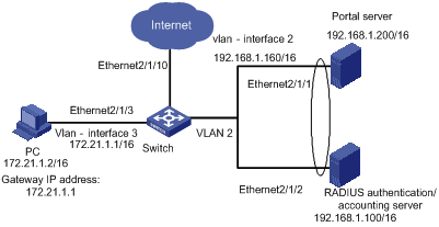
Figure 1-2 Network diagram for Portal Direct authentication method
III. Configuration procedure
& Note:
Only the configurations on switches are listed below. Configurations on the Portal servers and RADIUS authentication/accounting servers are not described here.
1) Configure the RADIUS scheme
# Create a RADIUS scheme named portal.
[H3C] radius scheme portal
# Set the server type of this RADIUS scheme as standard.
[H3C-radius-portal] server-type standard
# Set the primary authentication and accounting servers of this RADIUS scheme and their communication keys.
[H3C-radius-portal] primary authentication 192.168.1.100
[H3C-radius-portal] primary accounting 192.168.1.100
[H3C-radius-portal] key accounting hello
[H3C-radius-portal] key authentication hello
[H3C-radius-portal] user-name-format without-domain
[H3C-radius-portal] quit
2) Configure ISP domain
# Create an ISP domain named Portal.
[H3C] domain portal
# This ISP domain uses the RADIUS scheme named Portal.
[H3C-isp-portal] radius-scheme portal
[H3C-isp-portal] quit
# Set the default ISP domain of the system as Portal (optional).
[H3C] domain default enable portal
3) Configure Portal authentication
# Configure the portal server. Its name is newp, IP address is 192.168.1.200, key is test, port is 50100, and URL is http://192.168.1.200:81/portal.
[H3C] portal server newp ip 192.168.1.200 key test port 50100 url http://192.168.1.200/portal
# Set the Portal to run in the Direct authentication method.
[H3C] portal method direct
4) Enable Portal authentication on the VLAN interface connected with the user PC
# Configure VLAN 2.
[H3C] vlan 2
[H3C-vlan2] port ethernet 2/1/1 ethernet 2/1/2
[H3C] interface vlan-interface 2
[H3C-Vlan-interface2] ip address 192.168.1.160 255.255.0.0
[H3C-Vlan-interface2] quit
# Configure VLAN 3.
[H3C] vlan 3
[H3C-vlan3] port ethernet 2/1/3
[H3C-vlan3] quit
[H3C] interface vlan-interface 3
[H3C-Vlan-interface3] ip address 172.21.1.1 255.255.0.0
# Enable Portal authentication on VLAN interface 3.
[H3C-Vlan-interface3] portal newp
1.2.4 Portal ReDHCP Authentication Method Configuration Example
I. Network requirements
l Portal is enabled on the switch and Portal runs in the ReDHCP authentication method.
l Configure address pools on the DHCP server: 172.21.0.0/16 for public networks and 18.21.0.0/16 for private networks.
l The user was assigned a private address before passing Portal authentication. The user can access the external networks only after the user applies for a public address after passing Portal authentication.
II. Network diagram
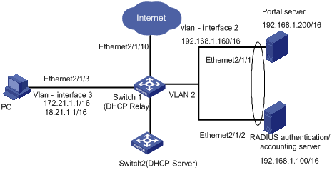
Figure 1-3 Network diagram for portal ReDHCP authentication method
III. Configuration procedure
& Note:
l Only the configurations related to the Portal ReDHCP authentication method are listed below. Refer to Portal Direct Authentication Method Configuration Example for the configurations on RADIUS schemes, ISP domains and Portal servers.
l When the Portal ReDHCP authentication method is adopted, the switch must be configured as DHCP Relay instead of DHCP Server. Additionally, the master IP address (public address) and the slave IP address (private IP address) must be configured on the Portal-enabled VLAN interface.
# Set the Portal to run in the ReDHCP authentication method.
[Switch1] portal method redhcp
# Configure the DHCP server.
[Switch2] dhcp server ip-pool dhcp_ip
[Switch2-dhcp-dhcp_ip] network 172.21.0.0 mask 255.255.0.0
[Switch2-dhcp-dhcp_ip] gateway-list 172.21.1.1
[Switch2-dhcp-dhcp_ip] quit
[Switch2] dhcp server ip-pool dhcp_ip2
[Switch2-dhcp-dhcp_ip2] network 18.21.0.0 mask 255.255.0.0
[Switch2-dhcp-dhcp_ip2] gateway-list 18.21.1.1
[Switch2-dhcp-dhcp_ip2] quit
# Configure VLAN 3
[Switch1] vlan 3
[Switch1-vlan3] port ethernet 2/1/3
[Switch1] interface vlan-interface 3
[Switch1-Vlan-interface3] ip address 172.21.1.1 255.255.0.0
[Switch1-Vlan-interface3] ip address 18.21.1.1 255.255.0.0 sub
# Configure the DHCP Relay address check (ip relay address must be specified as a VLAN interface in Up state).
[Switch1-Vlan-interface3] ip relay address 9.0.0.1
[Switch1-Vlan-interface3] dhcp select relay
[Switch1-Vlan-interface3] dhcp relay security address-check enable
# Enable Portal authentication function on VLAN-interface 3. The name of the Portal server is newp. Refer to Portal Direct Authentication Method Configuration Example for related configurations.
[Switch1-Vlan-interface3] portal newp
1.2.5 Layer 3 Portal Authentication Method Configuration Example
I. Network requirements
l The user PC2 accesses the switch through a router. Layer 3 Portal authentication method is enabled on the switch. User PC2 can access external networks after passing Portal authentication.
II. Network diagram
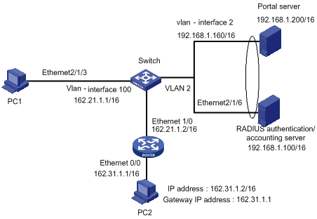
Figure 1-4 Network diagram for Layer 3 Portal authentication method
III. Configuration procedure
& Note:
Only the configurations related to the Layer 3 Portal authentication method are listed below. Refer to Portal Direct Authentication Method Configuration Example for the configurations on RADIUS schemes, ISP domains and Portal servers.
# Configure the authentication network segment
[H3C] portal auth-network 162.31.0.0 255.255.0.0 vlan 100
# Set the Portal to run in the Layer 3 Portal authentication method
[H3C] portal method layer3
# Configure VLAN 100
[H3C] vlan 100
[H3C-vlan100] port ethernet 2/1/6
[H3C-vlan100] quit
[H3C] interface vlan-interface 100
[H3C-Vlan-interface100] ip address 162.21.1.1 255.255.0.0
# Enable Portal authentication function on VLAN-interface 100. The name of the Portal server is newp. Refer to Portal Direct Authentication Method Configuration Example for related configurations.
[H3C-Vlan-interface100] portal newp
1.2.6 Configuring Direct Portal Authentication with Extended Functions
I. Network requirements
l The host is directly connected to the switch and the switch is configured for extended direct portal authentication. The host is assigned with a public network IP address manually or automatically by a DHCP server. When users using the host have passed identity authentication but have not passed security authentication, they can access only subnet 192.168.0.0/24. After passing security authentication, they can access unrestricted Internet resources.
l A RADIUS server serves as the authentication/accounting server.
II. Network diagram
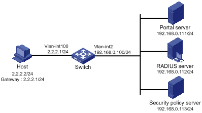
Figure 1-5 Configure direct portal authentication with extended functions
III. Configuration procedure
& Note:
You need to configure IP addresses for the devices as shown in Figure 1-5 and ensure that routes are available between the devices.
Configure the switch:
1) Configure a RADIUS scheme
# Create a RADIUS scheme named portal and enter its view.
[H3C] radius scheme portal
# Set the server type to extended.
[H3C-radius-portal] server-type extended
# Specify the primary authentication server and primary accounting server, and configure the keys for communication with the servers.
[H3C-radius-portal] primary authentication 192.168.0.112
[H3C-radius-portal] primary accounting 192.168.0.112
[H3C-radius-portal] key accounting hello
[H3C-radius-portal] key authentication hello
[H3C-radius-portal] user-name-format without-domain
# Specify the security policy server.
[H3C-radius-portal] security-policy-server 192.168.0.113
[H3C-radius-portal] quit
2) Configure an authentication domain
# Create an ISP domain named portal and enter its view.
[H3C] domain portal
# Configure the ISP domain to use RADIUS scheme portal.
[H3C-isp-portal] radius-scheme portal
[H3C-isp-portal] quit
# Configure domain portal as the default ISP domain.
[H3C] domain default enable portal
3) Configure the ACL (ACL 3000 ) for restricted resources and the ACL (ACL 3001) for unrestricted resources
& Note:
On the security policy server, you need to specify ACL 3000 as the isolation ACL and ACL 3001 as the security ACL.
[H3C] acl number 3000
[H3C-acl-adv-3000] rule permit ip destination 192.168.0.0 0.0.0.255
[H3C-acl-adv-3000] quit
[H3C] acl number 3001
[H3C-acl-adv-3001] rule permit ip
[H3C-acl-adv-3001] quit
4) Configure portal authentication
# Configure the portal server as follows:
l Name: newpt
l IP address: 192.168.0.111
l Key: test
l Port number: 50100
l URL: http://192.168.0.111/portal.
[H3C] portal server newp ip 192.168.0.111 key test port 50100 url http:// 192.168.0.111/portal
# Configure the portal running method as direct authentication.
[H3C] portal method direct
5) Enable portal authentication on the VLAN interface connecting the host
# Configure the IP address of VLAN-interface 100 and enable portal authentication on the VLAN interface.
[H3C] interface vlan-interface 100
[H3C–Vlan-interface100] ip address 2.2.2.1 255.255.255.0
[H3C–Vlan-interface100] portal newp
[H3C] quit
# Configure the IP address of the interface connected with the portal server.
[H3C] interface vlan-interface 2
[H3C–Vlan-interface2] ip address 192.168.0.100 255.255.255.0
1.2.7 Configuring Re-DHCP Portal Authentication with Extended Functions
I. Network requirements
l The host is directly connected to the switch and the switch is configured for re-DHCP authentication. The host is assigned with an IP address through the DHCP server. Before portal authentication, the host uses an assigned private IP address. After passing portal authentication, it can get a public IP address.
l When users using the host have passed identity authentication but have not passed security authentication, they can access only subnet 192.168.0.0/24. After passing the security authentication, they can access unrestricted Internet resources.
l A RADIUS server serves as the authentication/accounting server.
II. Network diagram
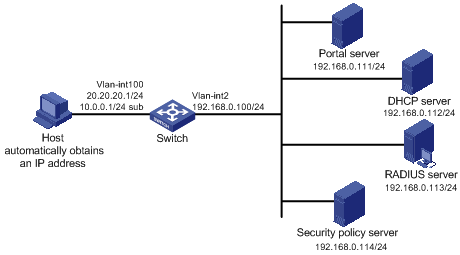
Figure 1-6 Configure re-DHCP portal authentication with extended functions
III. Configuration procedure
& Note:
l The following only lists configurations about the re-DHCP portal authentication. For configurations about RADIUS scheme, ISP domain, and portal server, refer to Portal Direct Authentication Method Configuration Example.
l For configuration on the DHCP server, refer to Portal ReDHCP Authentication Method Configuration Example.
l You need to configure IP addresses for the devices as shown in Figure 1-6 and ensure that routes are available between the devices.
Configure the switch:
# Configure the portal running method as re-DHCP authentication.
[H3C] portal method redhcp
# Configure the IP address of VLAN-interface 100.
[H3C] interface vlan-interface 100
[H3C–Vlan-interface100] ip address 20.20.20.1 255.255.255.0
[H3C–Vlan-interface100] ip address 10.0.0.1 255.255.255.0 sub
# Enable the DHCP relay address check function. (You need to specify the IP address of a VLAN interface that is in the up state for ip relay address.)
[H3C-Vlan-interface100] dhcp select relay
[H3C-Vlan-interface100] ip relay address 192.168.0.112
[H3C1-Vlan- interface100] dhcp relay security address-check enable
# Enable portal authentication on the interface connecting the host.
[H3C–Vlan-interface100] portal newpt
[H3C–Vlan-interface100] quit
# Configure the IP address of the interface connected with the portal server.
[H3C] interface vlan-interface 2
[H3C–Vlan-interface2] ip address 192.168.0.100 255.255.255.0
[H3C–Vlan-interface2] quit
1.2.8 Configuring Layer 3 Portal Authentication with Extended Functions
I. Network requirements
l Switch A is configured for extended Layer 3 portal authentication. When users have passed identity authentication but have not passed security authentication, they can access only subnet 192.168.0.0/24. After passing security authentication, they can access unrestricted Internet resources.
l The host accesses Switch A through Switch B.
l A RADIUS server serves as the authentication/accounting server.
II. Network diagram
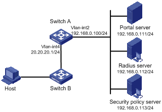
Figure 1-7 Configure Layer 3 portal authentication with extended functions
III. Configuration procedure
& Note:
l You need to configure IP addresses for the devices as shown in Figure 1-7 and ensure that routes are available between the devices.
l The following only lists configurations about the Layer 3 portal authentication. For configurations about RADIUS scheme, ISP domain, and ACL, refer to Portal Direct Authentication Method Configuration Example.
Configure Switch A:
# Configure the portal running method as Layer 3 portal authentication.
[SwitchA] portal method layer3
# Enable portal authentication on the interface connecting Switch B.
[SwitchA] interface vlan-interface 4
[SwitchA–Vlan-interface4] ip address 20.20.20.1 255.255.255.0
[SwitchA–Vlan-interface4] portal newp
[SwitchA–Vlan-interface4] quit
# Configure the IP address of the interface connected with the portal server.
[SwitchA] interface vlan-interface 2
[SwitchA–Vlan-interface2] ip address 192.168.0.100 255.255.255.0
[SwitchA–Vlan-interface2] quit
On Switch B, you need to configure a default route to subnet 192.168.0.0/24, setting the next hop as 20.20.20.1. The configuration steps are omitted.
1.3 Portal Authentication-free User and Free IP Address Configuration
1.3.1 Configuration Prerequisites
The prerequisite of Portal authentication-free user and free IP address configuration—the basic Portal configuration has been finished.
1.3.2 Configuration Procedure
Table 1-2 Portal authentication-free user and free IP address configuration procedure
|
To do... |
Use the command... |
Remarks |
|
|
Enter system view |
system-view |
— |
|
|
Configure free IP addresses |
portal free-ip ip-address [ mask | mask-length ] |
Up to eight free IP addresses can be configured. The Portal server will use one free IP address automatically, which cannot be removed or changed. |
|
|
Configure authentication-free users |
In system view |
portal free-user mac mac-address ip ip-address vlan vlan-id interface interface-type interface-number |
Up to 32 authentication-free users can be configured; The current port is used when this command is configured on a port. You need not specify the interface keyword |
|
In port view. |
portal free-user mac mac-address ip ip-address vlan vlan-id |
||
|
Display the information about Portal authentication-free user and free IP address configuration |
display portal [ free-ip | free-user ] |
— |
|
![]() Caution:
Caution:
l The ReDHCP authentication method requires that the IP address of an authentication-free user and the master IP address of the interface belong to the same network segment. The Direct authentication method requires that the IP address of an authentication-free user and that of the VLAN interface belong to the same network segment.
l This configuration takes effect after Portal is enabled in the VLAN that the authentication-free users belongs to.
l The Layer 3 Portal authentication method does not support the authentication-free user configuration.
1.3.3 Authentication-free User and Free IP Address Configuration Example
I. Network requirements
l Portal is enabled on the switch and Portal runs in the Direct authentication method.
l The user can access the internal server Server1 before passing Portal authentication.
l Server2 can access Internet without passing the authentication.
II. Network diagram
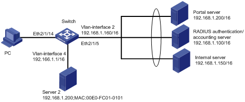
Figure 1-8 Network diagram for authentication-free user and free IP address configuration
III. Configuration procedure
& Note:
The following configurations are based on configurations in Portal Direct Authentication Method Configuration Example and the same configurations are not listed below.
1) Configure authentication-free users
# Configure VLAN4 and enable Portal on the VLAN interface 4
[H3C] vlan 4
[H3C-vlan4] port ethernet 2/1/4
[H3C-vlan4] quit
[H3C] interface vlan-interface 4
[H3C-Vlan-interface4] ip address 192.166.1.1 255.255.0.0
[H3C-Vlan-interface4] portal newp
[H3C-Vlan-interface4] quit
# Configure Server2 as an authentication-free user
[H3C] portal free-user mac 00E0-FC01-0101 ip 192.166.1.200 vlan 4 interface ethernet 2/1/4
2) Configure free IP addresses
# Add Ethernet interface 2/1/5 into the VLAN2 configured in Portal Direct Authentication Method Configuration Example
[H3C] vlan 2
[H3C-vlan2] port ethernet 2/1/5
[H3C-vlan2] quit
# Configure Server1 as a free IP address
[H3C] portal free-ip 192.168.1.300
1.4 Portal Rate Limit Function Configuration
1.4.1 Configuration Procedure
Table 1-3 Portal rate limit function configuration procedure
|
To do... |
Use the command... |
Remarks |
|
Enter system view |
system-view |
— |
|
Enter interface view |
interface Ethernet X/X/X |
— |
|
Configure the Portal rate limit function on upload interfaces |
portal upload interface |
By default, the Portal rate limit function is disabled. |
1.4.2 Portal Rate Limit Function Configuration Example
I. Network requirements
The upload interface for Portal rate limit is specified.
II. Network diagram
Refer to Figure 1-2.
III. Configuration procedure
# Specify Ethernet 2/1/10 as the upload interface for Portal rate limit.
<H3C> system-view
System View: return to User View with Ctrl+Z.
[H3C] interface Ethernet 2/1/10
[H3C-Ethernet2/1/10] portal upload-interface
1.5 Portal User Deletion
1.5.1 Portal User Deletion Procedure
Table 1-4 Portal user deletion procedure
|
To do... |
Use the command... |
Remarks |
|
Enter system view |
system-view |
— |
|
Delete the Portal user using the specified IP address |
portal delete-user ip-address |
— |