- Table of Contents
-
- H3C S9500 Operation Manual-Release1648[v1.24]-07 Security Volume
- 00-1Cover
- 01-Protocol Port Security Configuration
- 02-802.1x Configuration
- 03-AAA RADIUS HWTACACS Configuration
- 04-Password Control Configuration
- 05-SSH Configuration
- 06-IDS Linkage Configuration
- 07-Portal Configuration
- 08-VBAS Configuration
- 09-Traffic Accounting Configuration
- Related Documents
-
| Title | Size | Download |
|---|---|---|
| 06-IDS Linkage Configuration | 75.17 KB |
Table of Contents
Chapter 1 IDS Linkage Configuration
1.2.1 Configuration Description
1.3 IDS Linkage Configuration Example
1.4 Displaying IDS linkage Configuration
Chapter 1 IDS Linkage Configuration
When performing IDS Linkage configuration, go to these sections for information you are interested in:
l Overview
l IDS Linkage Configuration Example
l Displaying IDS linkage Configuration
1.1 Overview
1.1.1 Necessity
Users always resort to a single type of security products to satisfy a specific security need. For example, they purchase firewalls for purpose of preventing attacks of suspicious data packets, password machines for encrypting transmitted data, and intrusion detection systems (IDSs) for detecting intrusion.
With the increasing application, this expensive purchase method causes many management problems, as well as potential security problems. In most circumstances, security products need to cooperate with other security products and network devices, to ensure the system can detect and prevent corresponding attacks straight from the source. This kind of cooperation is called linkage. The switch supports IDS linkage, namely cooperation between the switch and IDS, to ensure effectively the security of the entire network.
1.1.2 Operations Involved
From the perspective of network security, IDS linkage contains the following operations:
l Filtering: Filters viruses, malicious ActiveX programs and others.
l Invasion detection: Detects suspicious behavior on the network based on protocol signatures, and then notifies firewalls and switches (routers) for processing.
1.1.3 Requirements for Switch
The switch should:
l Provide at least one monitor port, with the port rate of 100 Mbps or 1000 Mbps.
l Support SNMPv3, as well as proxy address setting.
l Support access control list (ACL) function to filter the IP address, TCP/UDP port and other fields in the packet header. Support setting life time and filtering type for each access list entry.
1.1.4 Requirements for IDS
The IDS supports SNMPv3, and can send access control messages to switches through SET operations.
1.2 IDS Linkage Configuration
1.2.1 Configuration Description
& Note:
To guarantee normal operation, you must configure SNMP on both the switch and IDS. For information about SNMP, refer to SNMP Configuration in the System Volume.
The following sections describe the IDS linkage configuration tasks:
l Configuring port mirroring
l Enabling IDS linkage on port
I. Configuring port mirroring
Port mirroring means you can duplicate the data from mirroring ports to the monitor ports, for data analysis and monitoring. The switch supports many-to-one mirroring, that is, you can duplicate packets from multiple ports to one monitor port. You can specify the packets sent by the specified ports to be monitored. You can specify the direction of the monitored packet. For example, you can set to monitor only outgoing packets on the specified ports.
For the S9500 series, you can use the mirroring group to configure port mirroring function. Each mirroring group contains one monitor port and a group of mirroring ports.
II. Enabling IDS linkage on a port
After configuring port mirroring, you must enable IDS linkage function on the corresponding port to make IDS linkage take effect.
1.2.2 Configuring IDS Linkage
Follow these steps to configure IDS linkage:
|
To do… |
Use the command… |
Remarks |
|
Enter system view |
system-view |
— |
|
Configure port mirroring |
mirroring-group groupid { inbound | outbound } mirroring-port-list mirrored-to mornitor-port |
Required For details, refer to the corresponding parts of the command manual. |
|
Enter Ethernet port view |
interface interface-type interface-number |
The prompt character for the Ethernet view depends on the input port. |
|
Enable IDS linkage on the port |
ids-acl enable |
Required |
|
Display port mirroring |
display mirroring-group [ groupid ] |
Optional Available in any view |
|
Display IDS linkage information |
display ids { all | controlled-interface | name name | source ip-addr | destination ip-addr } |
& Note:
l If the IDS linkage is enabled on the Ethernet port, the system may give alarms when you enable IDS linkage again. However, this does not affect the state of IDS linkage.
l The monitor port configured in a mirroring group connects the IDS monitoring port.
l The IDS linkage is enabled on the mirroring ports in the port monitoring group.
l The system identifies packet filter rules generated by IDS and does not save nodes generated by IDS. The packet filter rules generated by IDS are invisible even if you execute the display this command in port view.
1.3 IDS Linkage Configuration Example
I. Network requirements
l As shown in Figure 1-1, the IDS detects the host with IP address 192.168.1.20, which connects to the switch port Ethernet3/1/1.
l Before being controlled by the IDS, the host (192.168.1.20) can ping successfully the host (192.168.1.205, which connects to the switch port Ethernet3/1/3.)
l After being controlled by the IDS, the host (192.168.1.20) fails to ping host (192.168.1.205)
l The IDS device’s IP address is 192.168.1.247. Its management port connects the switch port Ethernet3/1/47; its monitoring port connects the switch port Ethernet3/1/48.
l The management port with the IP address 192.168.1.1 on the switch communicates with the IDS.
& Note:
Controlling means that the IDS monitors traffic data from mirroring ports. When detecting suspicious traffic data, the IDS device sends to a switch (router) or firewall the traffic data protocol header information (IP/TCP/UDP/ICMP) and action information. The switch (router) or firewall blocks the specified traffic or port.
II. Network diagram
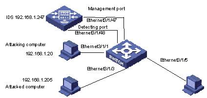
Figure 1-1 Network diagram for IDS linkage configuration
III. Configuration procedure
& Note:
Only the commands related to the switch are listed here.
<H3C> system-view
[H3C] mirroring-group 1 inbound Ethernet 3/1/1 mirrored-to Ethernet 3/1/48
[H3C]vlan 192
[H3C-vlan192]port Ethernet3/1/1 Ethernet3/1/3 Ethernet3/1/5 Ethernet3/1/47
[H3C-vlan192]interface vlan-interface 192
[H3C-Vlan-interface192]ip add 192.168.1.1 255.255.255.0
[H3C] interface Ethernet 3/1/1
[H3C-Ethernet3/1/1] ids-acl enable
[H3C-Ethernet3/1/1] display ids all
1.4 Displaying IDS linkage Configuration
|
To do… |
Use the command… |
Remarks |
|
Enable IDS linkage debugging |
debugging ids-acl |
By default, IDS linkage debugging is disabled. |
|
Display IDS linkage configuration information |
display ids { all | controlled-interface | name name | source ip-addr | destination ip-addr } |
You can execute the display ids command in any view. |