- Table of Contents
-
- H3C S7502 Ethernet Switch Installation Manual-(V1.02)
- 00-1Cover
- 01-Chapter 1 Product Overview
- 02-Chapter 2 Line Processing Units
- 03-Chapter 3 Installation Preparations
- 04-Chapter 4 Hardware Installation
- 05-Chapter 5 System Commissioning
- 06-Chapter 6 Hardware Maintenance
- 07-Chapter 7 Software Maintenance
- 08-Chapter 8 Troubleshooting
- 09-Appendix A Lightning Protection
- 10-Appendix B AC Power Cables Used in Different Countries or Regions
- Related Documents
-
| Title | Size | Download |
|---|---|---|
| 05-Chapter 5 System Commissioning | 287.59 KB |
Chapter 5 System Commissioning
5.1 Configuration Environment Setup
5.1.1 Setting up Networking Environment
5.1.2 Connecting the Console Cable
5.1.3 Setting Terminal Parameters.
5.2.3 Check after Power-on (Recommended)
Chapter 5 System Commissioning
5.1 Configuration Environment Setup
5.1.1 Setting up Networking Environment
A terminal (a PC in this example) is connected to the switch Console port through a Console cable.

Figure 5-1 Configuration environment
5.1.2 Connecting the Console Cable
Step 1: Plug the DB-9 female plug of the Console cable to the serial port of the PC or the terminal where the switch is to be configured.
Step 2: Connect the RJ-45 connector of the Console cable to the Console port of the switch.
5.1.3 Setting Terminal Parameters
Parameter requirements:
l Bits per second: 9600
l Data bits: 8
l Parity: none
l Stop bits: 1
l Flow control: none
l Emulation: VT100
Taking the PC running Windows XP HyperTerminal as an example, this section introduces how to set the terminal parameters.
& Note:
The terminal emulator on a Windows3.1 computer is Terminal and that on a Windows95/Windows98/Windows 2000/Windows NT/Windows XP/Windows ME computer is HyperTerminal.
Step 1: Start the PC and run the terminal emulator.
Step 2: Set the parameters for Windows XP HyperTerminal as follows:
1) Select Start > Programs/All Programs > Accessories > Communications > HyperTerminal to enter the HyperTerminal window to establish a new connection and the system will display the Connection Description dialog box.
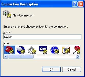
Figure 5-2 Connection description of HyperTerminal
2) Input the name of the new connection and click <OK>. Then there pops up the interface as shown in the following figure. Select the serial port to be used from the “Connect using” drop down list.
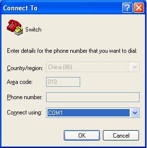
Figure 5-3 Setting serial port for HyperTerminal connection
3) After selecting serial ports, click <OK>. The following interface will pop up for setting serial port parameters. Set the bits per second to 9600, data bits to 8, parity check to none, stop bits to 1, and flow control to none.
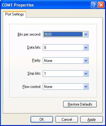
Figure 5-4 Setting serial port parameters
4) After setting serial port parameters, click <OK>. Then the system will enter the HyperTerminal dialogue box as shown in the following figure.
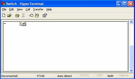
Figure 5-5 HyperTerminal interface
In the above dialogue box, select the Properties icon to enter the properties window. Click Settings to set the attributes (see the following figure). In this interface, select terminal emulation mode VT100 and then click <OK>.
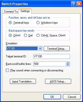
Figure 5-6 Setting terminal emulation mode in the property setting window
5.2 Power-on
5.2.1 Check before Power-on
Before powering on an Ethernet Switch, check that:
l The switch has been mounted steadily.
l All the cards have been correctly installed.
l All the communication cables, fibers, power cables, and grounding cables have been correctly connected.
l The voltage of power supply meets the requirements on the switch.
l The Console cable has been correctly connected. The computer or terminal for configuration has been started and the terminal parameter settings have been done.
![]() Caution:
Caution:
Before powering on the switch, confirm where the power switch of the equipment room is located, so that you will be able to power off in case of accidence.
5.2.2 Power-on
l Turn on the power supply of the switch.
l Power on the switch.
5.2.3 Check after Power-on (Recommended)
You are recommended to check as follows after powering on the switch to ensure the configurations thereafter.
l After a switch is powered on, the heat dissipation system starts working. You can hear the noise as the fan rotates and feel air flow out from the vent.
l Check if any system indicator on the SRPU indicates abnormal condition.
5.2.4 Starting the Interface
As the switch is started, the configuration terminal will yield the following output:
Starting......
RAM Line....OK
System is booting................
******************************************
* *
* H3C S7502 BOOTROM, Version 530 *
* *
******************************************
Copyright(c) 2004-2007 Hangzhou H3C Tech. Co., Ltd.
Creation date : Apr 20 2007, 14:48:52
CPU type : MPC8245
CPU Clock Speed : 300Mhz
BUS Clock Speed : 33Mhz
BOOT_FLASH type : M29W040B
Flash Size : 32MB
Memory Size : 256MB
S7502 main board self testing................................
SDRAM Data lines Selftest.................................OK!
SDRAM Address lines Selftest..............................OK!
SDRAM fast selftest.......................................OK!
Please check LEDs.....................LEDs selftest finished!
CPLD selftest.............................................OK!
The switch Mac address is .....................0000.0309.0004
Press Ctrl+B to enter Boot Menu... 0
Auto-booting...
Auto booting file is S7502.app
There are 4 files in this packet
SRPG app file <<srpu.app>> is...OK
Decompress Image...................................................
.......................................................OK!
Starting at 0x60000...
.......................................................................................................... .......................................................................................................... ..................................................................................
User interface Aux0/0 is available
Press ENTER to get started.
The displaying of the above indications indicates the completion of the switch auto-booting.
Press <Enter> and you will get the following output. By this time, you can start configuring the switch.
<H3C>
The S7502 provides a variety of command views. For the specific descriptions on the configuration commands and command line interfaces, refer to H3C S7500 Series Ethernet Switches Operation Manual and H3C S7500 Series Ethernet Switches Command Manual.