- Table of Contents
- Related Documents
-
| Title | Size | Download |
|---|---|---|
| 01-Text | 4 MB |
Table of Contents
1.8 S3600-28P-PWR-SI/S3600-28P-PWR-EI
1.9 S3600-52P-PWR-SI/S3600-52P-PWR-EI
1.10 Features of the S3600 Series
1.10.1 Features of the S3600-SI
1.10.2 Features of the S3600-EI
1.10.3 Features of the S3600-PWR-SI/S3600-PWR-EI
2.2.3 Electromagnetic Susceptibility
3.1.1 Mounting the Switch into a 19-Inch Standard Cabinet
3.1.2 Mounting the Switch on a Desktop/Workbench
3.2 Connecting the Power Cord and the Ground Wire
3.2.1 Connecting the AC Power Cord
3.2.2 Connecting the DC-Input Power Cord
3.2.3 Connecting the Ground Wire
3.4 Connecting the Switch to a Console Terminal
3.4.2 Connecting the Console Cable
3.5 Connecting and Removing Special Stack Interconnect Cables
3.5.1 Special Stack Interconnect Cables
3.5.2 Connecting Special Stack Interconnect Cables
3.5.3 Removing Special Stack Interconnect Cables
Chapter 4 Starting up the Switch at the Initial Boot
4.1 Setting up a Configuration Environment
4.2 Connecting the Console Cable
4.3 Setting Terminal Parameters
4.4.1 Verifying Installation before Power-up
Chapter 5 Loading Boot ROM and Host Software
5.1 Introduction to Loading Approaches
5.2 File attribute in Boot ROM
5.2.1 Introduction to File Attribute
5.2.2 Impact of File Attributes on Downloading and Booting
5.2.3 Setting the Attribute of a File
5.3.2 Loading Software from Console Port Using XModem
5.3.3 Loading Software from an Ethernet Port Using TFTP
5.3.4 Loading Software from an Ethernet Port Using FTP
5.4.1 Loading Software Remotely Using FTP
5.4.2 Loading Software Remotely Using TFTP
Chapter 6 Maintenance and Troubleshooting
6.1 Dealing with Loading Failures
6.2 Dealing with Password Loss
6.2.1 Dealing with User Password Loss
6.2.2 Recovering the Boot ROM Password
6.3 Dealing with Power System Failures
6.4 Dealing with Configuration System Failures
Chapter 1 Product Overview
1.1 Introduction
H3C S3600 Series Ethernet Switches developed by H3C are high-performance, high-density, easy-to-install, NMS-manageable intelligent Ethernet switches which support wire-speed Layer 2/3 switching.
Table 1-1 lists the models of H3C S3600 Series Ethernet Switches.
Table 1-1 Models of the S3600 series
|
Subseries |
Model |
Power supply |
Number of service ports |
Number of 100 Mbps ports |
Number of 1000 Mbps uplink ports |
Number of Console ports |
|
H3C S3600-SI |
S3600-28P-SI |
AC |
28 |
24 × 10Base-T/100Base-TX Ethernet ports |
4 × 1000Base-X SFP ports |
1 |
|
S3600-28TP-SI |
AC |
28 |
24 × 10Base-T/100Base-TX Ethernet ports |
2 × 1000Base-X SFP ports, 2 × 10/100/1000Base-T Ethernet ports |
1 |
|
|
S3600-52P-SI |
AC |
52 |
48 × 10Base-T/100Base-TX Ethernet ports |
4 × 1000Base-X SFP ports |
1 |
|
|
H3C S3600-PWR-SI |
S3600-28P-PWR-SI |
AC/DC |
28 |
24 × 10Base-T/100Base-TX Ethernet ports |
4 × 1000Base-X SFP ports |
1 |
|
S3600-52P-PWR-SI |
AC/DC |
52 |
48 × 10Base-T/100Base-TX Ethernet ports |
4 × 1000Base-X SFP ports |
1 |
|
|
H3C S3600-EI |
S3600-28P-EI |
AC/DC |
28 |
24 × 10Base-T/100Base-TX Ethernet ports |
4 × 1000Base-X SFP ports |
1 |
|
S3600-28F-EI |
AC/DC |
28 |
24 x 100Base-X SFP ports |
2 × 1000Base-X SFP ports, 2 × 10/100/1000Base-T Ethernet ports |
1 |
|
|
S3600-52P-EI |
AC/DC |
52 |
48 × 10Base-T/100Base-TX Ethernet ports |
4 × 1000Base-X SFP ports |
1 |
|
|
H3C S3600-PWR-EI |
S3600-28P-PWR-EI |
AC/DC |
28 |
24 × 10Base-T/100Base-TX Ethernet ports |
4 × 1000Base-X SFP ports |
1 |
|
S3600-52P-PWR-EI |
AC/DC |
52 |
48 × 10Base-T/100Base-TX Ethernet ports |
4 × 1000Base-X SFP ports |
1 |
& Note:
l The S3600-28P-PWR-SI, S3600-28P-PWR-EI, S3600-52P-PWR-SI, and S3600-52P-PWR-EI provides over-temperature protection mechanism. When the internal temperature exceeds 65°C (149°F), they will stop providing power from all ports. When the temperature is below 60°C (140°F), they will continue to provide power from all ports.
l Only the recommended PoE power supply can be used for the S3600-28P-PWR-SI, S3600-28P-PWR-EI, S3600-52P-PWR-SI, and S3600-52P-PWR-EI. The –48 VDC from the equipment room cannot be used directly. Otherwise, devices may be damaged.
1.2 S3600-28P-SI
1.2.1 Front Panel
I. Schematic diagram
The S3600-28P-SI provides twenty-four 10Base-T/100Base-TX auto-sensing Ethernet ports, four 1000Base-X SFP ports, and one Console port on the front panel, as shown in Figure 1-1.

|
(1) 10Base-T/100Base-TX auto-sensing Ethernet port status LEDs |
|
|
(2) 1000Base-X SFP port status LEDs |
(3) AC power LED |
|
(4) Mode LED |
(5) Mode button |
|
(6) 7-segment digital LED |
(7) Console port |
Figure 1-1 Front panel of the S3600-28P-SI
II. LEDs
The S3600-28P-SI provides one AC power LED, one mode LED, one 7-segment digital LED, twenty-four 10Base-T/100Base-TX auto-sensing Ethernet port status LEDs, and four 1000Base-X SFP port status LEDs on the front panel. You can learn how the switch operates by observing the LEDs listed in Table 1-2.
Table 1-2 LEDs on the front panel of the S3600-28P-SI
|
LED |
Mark |
Status |
Indication |
|||
|
Mode LED |
Mode |
Speed |
Solid green |
Rate information of 10Base-T/100Base-TX auto-sensing Ethernet ports, and 1000Base-X SFP ports |
||
|
Duplex |
Solid yellow |
Duplex information of 10Base-T/100Base-TX auto-sensing Ethernet ports, and 1000Base-X SFP ports |
||||
|
AC Power LED |
PWR |
Solid green |
The switch is started normally. |
|||
|
Flashing green (1 Hz) |
The system is running a power-on self-test (POST) or downloading software. |
|||||
|
Solid red |
The system fails a POST or a fault occurs. |
|||||
|
Flashing yellow (1 Hz) |
Some ports fail a POST or malfunctions occur. |
|||||
|
OFF |
The power is disconnected. |
|||||
|
10Base-T/100 Base -TX port status LED |
— |
Speed |
Green |
ON |
A 100 Mbps link is present. |
|
|
Flashing |
Data is being received/sent on the port. |
|||||
|
Yellow |
ON |
A 10 Mbps link is present. |
||||
|
Flashing |
Data is being received/sent on the port. |
|||||
|
Flashing yellow (3 Hz) |
The port fails the POST. |
|||||
|
OFF |
No link is present. |
|||||
|
Duplex |
Green |
ON |
The port is operating in full duplex mode. |
|||
|
Flashing |
Data is being received/sent on the port. |
|||||
|
Yellow |
ON |
The port is operating in half duplex mode. |
||||
|
Flashing |
Data is being received/sent on the port. |
|||||
|
Flashing yellow (3 Hz) |
The port fails the POST. |
|||||
|
OFF |
No data is being received/sent on the port. |
|||||
|
1000 Base-SFP port status LED |
— |
Speed |
Green |
ON |
A 1000 Mbps link is present. |
|
|
Flash |
Data is being received/sent on the port. |
|||||
|
Flashing yellow (3 Hz) |
The port fails POST. |
|||||
|
OFF |
No link is present. |
|||||
|
Duplex |
Green |
ON |
The port is operating in full duplex mode. |
|||
|
Flash |
Data is being received/sent on the port. |
|||||
|
Flashing yellow (3 Hz) |
The port fails the POST. |
|||||
|
OFF |
The port is not connected. |
|||||
|
PoE mode |
Flashing green (3 Hz) |
The port fails the POST. |
||||
|
OFF |
–– |
|||||
|
Status LED of the 1000Base-X SFP port serving as a fabric port |
— |
Speed |
Green |
ON |
The port is connected, and the device is in an IRF loop fabric. |
|
|
Flashing |
Data is being received/sent on the port. |
|||||
|
Yellow |
ON |
The port is connected, and the device is in an IRF chain fabric. |
||||
|
Flash |
Data is being received/sent on the port. |
|||||
|
Flashing green (3Hz) |
A fault occurs to Fabric. |
|||||
|
Flashing yellow (3 Hz) |
The port fails the POST. |
|||||
|
OFF |
The port is not connected. |
|||||
|
Duplex |
Green |
ON |
The port is in full duplex mode. |
|||
|
Flashing |
Data is being received/sent on the port. |
|||||
|
Flashing yellow (3 Hz) |
The port fails the POST. |
|||||
|
OFF |
The port is not connected. |
|||||
|
PoE |
Flashing yellow (3 Hz) |
The port fails the POST. |
||||
|
OFF |
–– |
|||||
|
7-segment digital LED |
Unit |
POST running |
The PWR LED flashes green |
Displays the POST test ID (in the range of 1 to 9). |
||
|
POST failed |
The PWR LED flashes yellow |
Flashes the POST test ID of the failed test. |
||||
|
The PWR LED is solid red |
||||||
|
Software downloading |
The PWR LED flashes green |
A bar rotates clockwise around the LED. |
||||
|
Fan failed |
The PWR LED is solid red |
Displays “F”. |
||||
|
Unit ID |
Button released |
Displays the unit ID in the fabric; and displays “1” if there is only one unit. |
||||
III. Attributes of the 10Base-T/100Base-TX Ethernet ports
Table 1-3 Attributes of the 10Base-T/100Base-TX Ethernet Ports on the S3600-28P-SI
|
Attribute |
Description |
|
Connector |
RJ-45 |
|
Number of ports |
24 |
|
Rate |
l 10 Mbps, half duplex/full duplex l 100 Mbps, half-duplex/full duplex l MDI/MDI-X auto-sensing |
|
Standard |
IEEE 802.3u |
|
Transmission distance over the selected medium |
100 m (328.08 ft) over the category-5 unshielded twisted pair (UTP) cable |
IV. Console port
The S3600-28P-SI provides one EIA/TIA-232 compliant Console port for local or remote configuration. Table 1-4 lists the attributes of the Console port.
Table 1-4 Console port attributes
|
Attribute |
Description |
|
Connector |
RJ-45 |
|
Standard |
Asynchronous EIA/TIA-232 |
|
Baud rate |
9600 bps (default) |
|
Service |
l Connection to the ASCII terminal l Connection to the serial interface of a local terminal (a PC for example) or to a remote terminal through a pair of modems), where terminal emulation program is run |
V. Attributes of the 1000Base-X SFP ports
The S3600-28P-SI provides four 1000Base-X SFP ports (numbered from 25 to 28) on its front panel.
SFP modules allow for great flexibility because they are hot swappable and user configurable.
Table 1-5 lists the available SFP modules.
Table 1-5 1000Base-X SFP modules
|
Type |
Model |
|
|
SFP optical module |
1000Base-X SFP module |
SFP-GE-SX-MM850-A |
|
SFP-GE-LX-SM1310-A |
||
|
SFP-GE-LH40-SM1310 |
||
|
SFP-GE-LH40-SM1550 |
||
|
SFP-GE-LH70-SM1550 |
||
|
SFP electrical interface module |
SFP-GE-T |
|
& Note:
l The types of 1000Base-X SFP modules may be subject to changes without notice. Consult H3C marketing personnel or technical support personnel to obtain the latest information about SFP modules.
l For specifications of SFP modules, refer to H3C Low End Series Ethernet Switches Pluggable Modules Manual.
1.2.2 Rear Panel
I. Schematic diagram
The S3600-28P-SI provides an AC power socket and a grounding screw on its rear panel, as shown in Figure 1-2.

|
(1) AC power socket |
(2) Grounding screw |
Figure 1-2 Rear panel of the S3600-28P-SI
II. Power system
The following gives the input voltage specifications for the S3600-28P-SI:
Rated voltage range: 100 VAC to 240 VAC, 50/60 Hz
Input voltage range: 90 VAC to 264 VAC, 47 to 63 Hz
1.3 S3600-28TP-SI
1.3.1 Front Panel
I. Schematic diagram
The S3600-28TP-SI provides twenty-four 10Base-T/100Base-TX auto-sensing Ethernet ports, two 1000Base-X SFP ports, two 10/100/1000Base-T auto-sensing Ethernet ports, and one Console port on the front panel, as shown in Figure 1-3.

|
(1) 10Base-T/100Base-TX auto-sensing Ethernet port status LEDs |
|
|
(2) 1000Base-X SFP port status LEDs |
|
|
(3) 10/100/1000Base-T auto-sensing Ethernet port status LEDs |
|
|
(4) Console port |
|
|
(5) 7-segment digital LED |
(6) AC power LED |
|
(7) Mode LED |
(8) Mode button |
Figure 1-3 Front panel of the S3600-28TP-SI
II. LEDs
The S3600-28TP-SI provides one power LED, one DC power LED, one mode LED, one 7-segment digital LED, twenty-four 10Base-T/100Base-TX Ethernet port status LEDs, two 1000Base-X SFP port status LEDs, and two 10/100/1000Base-T auto-sensing Ethernet port status LEDs. You can learn how the switch operates by observing the LEDs listed in Table 1-6.
Table 1-6 LEDs on the front panel of the S3600-28TP-SI
|
LED |
Mark |
Status |
Indication |
||
|
AC power LED |
PWR |
Solid green |
The switch is started normally. |
||
|
Flashing green (1Hz) |
The system is running a POST or downloading software. |
||||
|
Solid red |
The system fails the POST or a fault occurs. |
||||
|
Flashing yellow (1Hz) |
Some ports fail a POST or malfunctions occur. |
||||
|
OFF |
The power is disconnected. |
||||
|
Mode LED |
Mode |
Speed |
Solid green |
Rate information of 10Base-T/100Base-TX Ethernet ports, and 1000Base-X SFP ports. |
|
|
Duplex |
Solid yellow |
Duplex information of 10Base-T/100Base-TX Ethernet ports, and 1000Base-X SFP ports. |
|||
|
10Base-T/100Base-TX port status LED |
— |
Speed |
Green |
ON |
A 100 Mbps link is present. |
|
Flashing |
Data is being received/sent on the port. |
||||
|
Yellow |
On |
A 10 Mbps link is present. |
|||
|
Flashing |
Data is being received/sent on the port. |
||||
|
Flashing yellow (3Hz) |
The port fails a POST. |
||||
|
OFF |
No link is present. |
||||
|
Duplex |
Green |
ON |
The port is operating in full duplex mode. |
||
|
Flashing |
Data is being received/sent on the port. |
||||
|
Yellow |
ON |
The port is operating in half duplex mode. |
|||
|
Flashing |
Data is being received/sent on the port. |
||||
|
Flashing yellow (3Hz) |
The port fails a POST. |
||||
|
OFF |
No data is being received/sent on the port. |
||||
|
1000Base-X SFP port status LED |
— |
Speed |
Green |
ON |
A 1000 Mbps link is present. |
|
Flashing |
Data is being received/sent on the port. |
||||
|
Flashing yellow (3Hz) |
The port fails a POST. |
||||
|
OFF |
No link is present. |
||||
|
Duplex |
Green |
ON |
The port is operating in full duplex mode. |
||
|
Flashing |
Data is being received/sent on the port. |
||||
|
Flashing yellow (3Hz) |
The port fails a POST. |
||||
|
OFF |
No link is present. |
||||
|
PoE |
Flashing green (3Hz) |
The port fails a POST. |
|||
|
OFF |
— |
||||
|
10/100/ 1000Base-T Ethernet port status LED |
— |
Speed |
Green |
ON |
A 1000 Mbps link is present. |
|
Flashing |
Data is being received/sent on the port. |
||||
|
Yellow |
ON |
A 10/100 Mbps link is present. |
|||
|
Flashing |
Data is being received/sent on the port. |
||||
|
Flashing yellow (3Hz) |
The port fails a POST. |
||||
|
OFF |
No link is present. |
||||
|
Duplex |
Green |
ON |
The port is operating in full duplex mode. |
||
|
Flashing |
Data is being received/sent on the port. |
||||
|
Yellow |
ON |
The port is operating in half duplex mode. |
|||
|
Flashing |
Data is being received/sent on the port |
||||
|
Flashing yellow (3Hz) |
The port fails POST. |
||||
|
OFF |
No data is being received/sent on the port. |
||||
|
7-segment digital LED |
Unit |
POST running |
The PWR LED flashes green |
Displays the POST test ID (in the range of 1 to 9). |
|
|
POST failed |
The PWR LED flashes yellow |
Flashes the POST test ID of the failed test. |
|||
|
The PWR LED is solid red |
|||||
|
Software loading |
The PWR LED flashes green |
A bar rotates clockwise around the LED. |
|||
|
Fan failure |
The PWR LED is solid red |
Displays “F”. |
|||
|
Unit ID |
Button released |
Displays the unit ID in the fabric, and displays “1” if there is only one unit. |
|||
III. Attributes of the 10Base-T/100Base-TX Ethernet ports
The S3600-28TP-SI provides twenty-four 10Base-T/100Base-TX Ethernet ports (numbered from 1 to 24) on the front panel. For attributes of these ports, see Table 1-3.
IV. Attributes of the 1000Base-X SFP ports
The S3600-28TP-SI provides two 1000Base-X SFP ports numbered 25 and 26 on the front panel.
SFP modules allow for great flexibility because they are hot swappable and user configurable.
Table 1-5 lists the available SFP modules.
& Note:
l The types of 1000Base-X SFP modules may be subject to changes without notice. Consult H3C marketing personnel or technical support personnel to obtain the latest information about SFP modules.
l For specifications of SFP modules, refer to H3C Low End Series Ethernet Switches Pluggable Modules Manual.
V. Attributes of the 10/100/1000Base-T Ethernet ports
The S3600-28TP-SI can provide two 10/100/1000Base-T Ethernet ports numbered 27 and 28 on the front panel. For attributes of these two ports, see Table 1-7.
Table 1-7 Attributes of the 10/100/1000Base-T Ethernet ports on the S3600-28TP-SI
|
Attribute |
Description |
|
Connector |
RJ-45 |
|
Number of ports |
2 |
|
Rate |
l 10/100 Mbps, half duplex/full duplex l 1000 Mbps, full duplex l MDI/MDI-X auto-sensing |
|
Standard |
l IEEE 802.3u l IEEE 802.3ab |
|
Transmission distance over the selected medium |
100 m (328.08 ft) over the category-5 unshielded twisted pair (UTP) cable |
VI. Console port
The S3600-28TP-SI provides one EIA/TIA-232 compliant Console port for local or remote switch configuration. For the attributes, see Table 1-4.
1.3.2 Rear Panel
I. Schematic diagram
The S3600-28TP-SI provides an AC power socket and a grounding screw on the rear panel, as shown in Figure 1-4.

|
(1) AC power socket |
(2) Grounding screw |
Figure 1-4 Rear panel of the S3600-28TP-SI
II. Power system
The following gives the input voltage specifications for the S3600-28TP-SI:
Rated voltage range: 100 VAC to 240 VAC, 50/60 Hz
Input voltage range: 90 VAC to 264 VAC, 47 to 63 Hz
1.4 S3600-52P-SI
1.4.1 Front Panel
I. Schematic diagram
On the front panel, the S3600-52P-SI provides forty-eight 10Base-T/100Base-TX auto-sensing Ethernet ports, four 1000Base-X SFP ports, and one Console port, as shown in Figure 1-5.

|
(1) 10Base-T/!00Base-TX auto-sensing Ethernet port status LEDs |
(2) Console port |
|
(3) 7-segment digital LED |
(4) Mode button |
|
(5) Mode LED |
(6) AC power LED |
|
(7) 1000Base-X SFP port status LEDs |
|
Figure 1-5 Front panel of the S3600-52P-SI
II. LEDs
On the front panel, the S3600-52P-SI provides one AC power LED, one mode LED, one 7-segment digital LED, forty-eight 10Base-T/100Base-TX Ethernet port status LEDs, and four 1000Base-X SFP port status LEDs. You can learn how the switch operates by observing the LEDs listed in Table 1-2.
III. Attributes of 10Base-T/100Base-TX Ethernet ports
Table 1-8 Attributes of the 10Base-T/100Base-TX Ethernet ports on the S3600-52P-SI
|
Attribute |
Description |
|
Connector |
RJ-45 |
|
Number of ports |
48 |
|
Rate |
l 10 Mbps, half duplex/full duplex l 100 Mbps, half-duplex/full duplex l MDI/MDI-X auto-sensing |
|
Standard |
IEEE 802.3u |
|
Transmission distance over the selected medium |
100 m (328.08 ft) over the category-5 unshielded twisted pair (UTP) cable |
IV. Console port
The S3600-52P-SI provides one EIA/TIA-232 compliant Console port for local or remote switch configuration. For the attributes, see Table 1-4.
V. Attributes of the 1000Base-X SFP ports
The S3600-52P-SI provides four 1000Base-X SFP ports numbered 49 to 52 on the front panel.
SFP modules allow for great flexibility because they are hot swappable and user configurable.
Table 1-5 lists the available SFP modules.
& Note:
l The types of 1000Base-X SFP modules may be subject to changes without notice. Consult H3C marketing personnel or technical support personnel to obtain the latest information about SFP modules.
l For specifications of SFP modules, refer to H3C Low End Series Ethernet Switches Pluggable Modules Manual.
1.4.2 Rear Panel
I. Schematic diagram
The S3600-52P-SI provides an AC power socket and a grounding screw on its rear panel, as shown in Figure 1-6.

|
(1) AC power socket |
(2) Grounding screw |
Figure 1-6 Rear panel of the S3600-52P-SI
II. Power system
The following gives the input voltage specifications for the S3600-52P-SI:
Rated voltage range: 100 VAC to 240 VAC, 50/60 Hz
Input voltage range: 90 VAC to 264 VAC, 47 to 63 Hz
1.5 S3600-28P-EI
1.5.1 Front Panel
I. Schematic diagram
On the front panel, the S3600-28P-EI provides twenty-four 10Base-T/100Base-TX auto-sensing Ethernet ports, four 1000Base-X SFP ports, and one Console port, as shown in Figure 1-7.

|
(1) 10Base-T/100Base-TX auto-sensing Ethernet port status LEDs |
|
|
(2) 1000Base-X SFP port status LEDs |
(3) Console port |
|
(4) 7-segment digital LED |
(5) DC power LED |
|
(6) AC power LED |
(7) Mode LED |
|
(8) Mode button |
|
Figure 1-7 Front panel of the S3600-28P-EI
II. LEDs
On the front panel, the S3600-28P-EI provides one AC power LED, one DC power LED, one mode LED, one 7-segment digital LED, twenty-four 10Base-X/100Base-TX auto-sensing Ethernet port status LEDs, and four 1000Base-X SFP port status LEDs. You can learn how the switch operates by observing the LEDs listed in Table 1-9.
Table 1-9 LEDs on the front panel of the S3600-28P-EI
|
LED |
Mark |
Status |
Indication |
||
|
AC power LED |
PWR |
Solid green |
The system passes the Power-On Self-Test (POST) and is operating normally. |
||
|
Flashing green (1 Hz) |
The system is running a POST or is downloading software. |
||||
|
Solid red |
The POST of the system fails or a serious fault is detected. |
||||
|
Flashing yellow (1 Hz) |
Some ports fail to pass the POST and some functions are disabled. |
||||
|
OFF |
The power is disconnected. |
||||
|
DC power LED |
RPS |
Solid green |
Both the internal AC power supply and the DC input are normal. |
||
|
Solid yellow |
The internal AC power supply fails or is disconnected, but the DC input is normal. |
||||
|
OFF |
The DC input is not connected. |
||||
|
Mode LED |
Mode |
Speed |
Solid green |
Rate information of the 10Base-T/100Base-TX Ethernet ports and the 1000Base-X SFP ports. |
|
|
Duplex |
Solid yellow |
Duplex information of 10Base-T/100Base-TX Ethernet ports and the 1000Base-X SFP ports. |
|||
|
7- segment digital LED |
Unit |
POST running |
PWR flashes green (1 Hz) |
Displays the POST test ID (in the range of 1 to 9). |
|
|
POST failed |
The PWR LED flashes yellow. |
Flashes the POST test ID of the failed test. |
|||
|
The PWR LED is solid red. |
|||||
|
Software loading |
The PWR LED flashes green. |
A bar rotates clockwise around the LED. |
|||
|
Fan failure |
The PWR LED is red |
Displays “F”. |
|||
|
Unit ID |
Button released |
Displays the unit ID in the fabric; and displays “1” if there is only one unit. |
|||
|
10Base-T/100Base-TX Ethernet port status LED |
— |
Speed |
Green |
ON |
A 100 Mbps link is present. |
|
Flash |
Data is being received/sent on the port |
||||
|
Yellow |
ON |
A 10 Mbps link is present. |
|||
|
Flash |
Data is being received/sent on the port |
||||
|
Flashing yellow (3 Hz) |
The port fails POST. |
||||
|
OFF |
No link is present. |
||||
|
Duplex |
Green |
ON |
The port is operating in full duplex mode. |
||
|
Flash |
Data is being received/sent on the port |
||||
|
Yellow |
ON |
The port is operating in half duplex mode. |
|||
|
Flash |
Data is being received/sent on the port |
||||
|
Flashing yellow (3 Hz) |
The port fails POST. |
||||
|
OFF |
No data is being received/sent on the port. |
||||
|
1000Base-X SFP port LED |
— |
Speed |
Green |
ON |
A 1000 Mbps link is present. |
|
Flash |
Data is being received/sent on the port |
||||
|
Flashing yellow (3 Hz) |
The port fails POST. |
||||
|
OFF |
No link is present. |
||||
|
Duplex |
Green |
ON |
The port is operating in full duplex mode |
||
|
Flash |
Data is being received/sent on the port |
||||
|
Flashing yellow (3 Hz) |
The port fails POST. |
||||
|
OFF |
No data is being received/sent on the port. |
||||
|
PoE mode |
Flashing green (3 Hz) |
The port fails POST. |
|||
|
OFF |
–– |
||||
|
Status LED of 1000Base-X SFP port serving as a fabric port |
— |
Speed |
Green |
ON |
The port is connected, and the device is in an IRF loop fabric. |
|
Flash |
Data is being received/sent on the port. |
||||
|
Yellow |
ON |
The port is connected and the device is in an IRF chain fabric. |
|||
|
Flash |
Data is being received/sent on the port. |
||||
|
Flashing green (3Hz) |
A fault occurs to the fabric. |
||||
|
Flashing yellow (3 Hz) |
The port fails to pass POST. |
||||
|
OFF |
The port is not connected. |
||||
|
Duplex |
Green |
ON |
The port is operating in full duplex mode. |
||
|
Flash |
Data is being received/sent on the port. |
||||
|
Flashing yellow (3 Hz) |
The port fails to pass POST. |
||||
|
OFF |
The port is not connected. |
||||
|
PoE mode |
Flashing yellow (3 Hz) |
The port fails a POST. |
|||
|
OFF |
–– |
||||
III. Attributes of the 10Base-T/100Base-TX Ethernet ports
See Table 1-3.
IV. Console port
The S3600-28P-EI provides one EIA/TIA-232 compliant Console port for local or remote switch configuration. For the attributes, see Table 1-4.
V. Attributes of the 1000Base-X SFP ports
The S3600-28P-EI provides four 1000Base-X SFP ports numbered 25 to 28 on the front panel.
SFP modules allow for great flexibility because they are hot swappable and user configurable.
Table 1-5 lists the available SFP modules.
& Note:
l The types of 1000Base-X SFP modules may be subject to changes without notice. Consult H3C marketing personnel or technical support personnel to obtain the latest information about SFP modules.
l For specifications of SFP modules, refer to H3C Low End Series Ethernet Switches Pluggable Modules Manual.
1.5.2 Rear Panel
I. Schematic diagram
The S3600-28P-EI provides an AC power socket, a DC power socket and a grounding screw on the rear panel, as shown in Figure 1-8.

|
(1) AC power socket |
(2) DC power socket |
(3) Grounding screw |
Figure 1-8 Rear panel of the S3600-28P-EI
II. Power system
l AC power
Rated voltage range: 100 VAC to 240 VAC, 50 Hz/60 Hz
Input voltage range: 90 VAC to 264 VAC, 47 Hz to 63 Hz
l DC power
Rated voltage range: –48 VDC to –60 VDC
Input voltage range: –36 VDC to –72 VDC
1.6 S3600-28F-EI
1.6.1 Front Panel
I. Schematic diagram
On the front panel, the S3600-28F-EI provides twenty-four 100Base-X SFP ports, two 1000Base-X SFP ports, two 10/100/1000Base-T auto-sensing Ethernet ports, and one Console port, as shown in Figure 1-9.

|
(1) 100Base-X SFP port status LEDs |
(2) 1000Base-X SFP port status LEDs |
|
(3) 10/100/1000Base-T auto-sensing Ethernet port status LEDs |
|
|
(4) Console port |
(5) 7-segment digital LED |
|
(6) DC power LED |
(7) AC Power LED |
|
(8) Mode LED |
(9) Mode button |
Figure 1-9 Front panel of the S3600-28F-EI
II. LEDs
On the front panel, the S3600-28F-EI provides one AC power LED, one DC power LED, one mode LED, one 7-segment digital LED, twenty-four 100Base-X SFP port status LEDs, four 1000Base-X SFP port status LEDs, and two 10/100/1000Base-T auto-sensing Ethernet port status LEDs. You can learn how the switch operates by observing the LEDs listed in Table 1-10.
Table 1-10 LEDs on the front panel of the S3600-28F-EI
|
LED |
Mark |
Color |
Indicates |
||
|
AC Power LED |
PWR |
Solid green |
The system passes the Power-On Self-Test (POST) and is operating normally. |
||
|
Flashing green (1 Hz) |
The system is going through the POST or is downloading software. |
||||
|
Solid red |
The POST of the system fails or a serious fault is detected. |
||||
|
Flashing yellow (1 Hz) |
Some ports fail to pass the POST and some functions are disabled. |
||||
|
OFF |
The power is disconnected. |
||||
|
Mode LED |
Mode |
Speed |
Solid green |
Rate information of the 10Base-T/100Base-TX Ethernet ports and the 1000Base-X SFP ports. |
|
|
Duplex |
Solid yellow |
Duplex information of 10Base-T/100Base-TX Ethernet ports and the 1000Base-X SFP ports. |
|||
|
7- segment digital LED |
Unit |
POST running |
The PWR LED flashes green. |
Flashes the POST test ID of the failed test. |
|
|
POST failed |
The PWR LED flashes yellow. |
POST test ID of the failed test. A bar rotates clockwise around the LED. |
|||
|
PWR stays red |
|||||
|
Software loading |
The PWR LED flashes green. |
Displays “F”. |
|||
|
Fan failure |
The PWR LED is solid red |
Displays the unit ID in the fabric; and displays “1” if there is only one unit. |
|||
|
Unit id |
Button released |
Flashes the POST test ID of the failed test. |
|||
|
100Base-X SFP port status LED |
— |
Speed |
Green |
ON |
A 100 Mbps link is present. |
|
Flash |
Data is being received/sent on the port |
||||
|
Flashing yellow (3 Hz) |
The port fails POST. |
||||
|
OFF |
No link is present. |
||||
|
Duplex |
Green |
ON |
The port is operating in full duplex mode |
||
|
Flash |
Data is being received/sent on the port |
||||
|
Flashing yellow (3 Hz) |
The port fails POST. |
||||
|
OFF |
No data is being received/sent on the port. |
||||
|
1000Base-X SFP port status LED |
— |
Speed |
Green |
ON |
A 1000 Mbps link is present. |
|
Flash |
Data is being received/sent on the port |
||||
|
Flashing yellow (3 Hz) |
The port fails POST. |
||||
|
OFF |
No link is present. |
||||
|
Duplex |
Green |
ON |
The port is operating in full duplex mode |
||
|
Flash |
Data is being received/sent on the port |
||||
|
Flashing yellow (3 Hz) |
The port fails POST. |
||||
|
OFF |
No link is present. |
||||
|
PoE |
Flashing green (3 Hz) |
The port fails POST. |
|||
|
OFF |
–– |
||||
|
Status LED of 1000Base-X SFP port serving as a fabric port |
— |
Speed |
Green |
ON |
The port is connected, and the device is in an IRF loop fabric. |
|
Flash |
Data is being received/sent on the port |
||||
|
Yellow |
ON |
The port is connected, and the device is in an IRF chain fabric. |
|||
|
Flash |
Data is being received/sent on the port |
||||
|
Flashing green (3 Hz) |
A fault occurs to the fabric. |
||||
|
Flashing yellow (3 Hz) |
The port fails POST. |
||||
|
OFF |
The port is not connected. |
||||
|
Duplex |
Green |
ON |
The port is operating in full duplex mode |
||
|
Flash |
Data is being received/sent on the port |
||||
|
Flashing yellow (3 Hz) |
The port fails POST. |
||||
|
OFF |
The port is not connected. |
||||
|
PoE |
OFF |
No data is being received/sent |
|||
|
Flashing yellow (3 Hz) |
The port fails POST. |
||||
|
10/100/1000Base-T port LED |
— |
Speed |
Green |
ON |
A 1000 Mbps link is present. |
|
Flash |
Data is being received/sent on the port |
||||
|
Yellow |
ON |
A 10/100 Mbps link is present. |
|||
|
Flash |
Data is being received/sent on the port |
||||
|
Flashing yellow (3 Hz) |
The port fails POST. |
||||
|
OFF |
The port is not connected. |
||||
|
Duplex |
Green |
ON |
The port is operating in full duplex mode |
||
|
Flash |
Data is being received/sent on the port |
||||
|
Yellow |
ON |
The port is operating in half duplex mode |
|||
|
Flash |
Data is being received/sent on the port |
||||
|
Flashing yellow (3 Hz) |
The port fails POST. |
||||
|
OFF |
No data is being received/sent on the port. |
||||
|
10/100/1000Base-T Fabric port LED |
— |
Speed |
Green |
ON |
The port is connected, and the device is in an IRF loop fabric. |
|
Flash |
Data is being received/sent on the port |
||||
|
Yellow |
ON |
The port is connected, and the device is in an IRF chain fabric. |
|||
|
Flash |
Data is being received/sent on the port |
||||
|
Flashing green (3 Hz) |
A fault occurs to the fabric. |
||||
|
Flashing yellow (3 Hz) |
The port fails POST. |
||||
|
OFF |
The port is not connected. |
||||
|
Duplex |
Green |
ON |
The port is operating in full duplex mode |
||
|
Flash |
Data is being received/sent on the port |
||||
|
Flashing yellow (3 Hz) |
The port fails POST. |
||||
|
OFF |
The port is not connected. |
||||
|
PoE |
OFF |
No data is being received/sent |
|||
|
Flashing yellow (3 Hz) |
The port fails POST. |
||||
III. Attributes of the 100Base-X SFP ports
The S3600-28F-EI provides twenty-four 100Base-X SFP optical ports numbered from 1 to 24 on the front panel.
SFP modules allow for great flexibility because they are hot swappable and user configurable.
Table 1-11 lists the available 100Base-X SFP modules.
Table 1-11 100Base-X SFP modules
|
Type |
Model |
|
100Base-X SFP module |
SFP-FE-SX-MM1310-A |
|
SFP-FE-LX-SM1310-A |
|
|
SFP-FE-LH40-SM1310 |
|
|
SFP-FE-LH80-SM1550 |
IV. Attributes of the 1000Base-X SFP ports
The S3600-28F-EI provides two 1000Base-X SFP ports numbered 25 and 26 on the front panel.
SFP modules allow for great flexibility because they are hot swappable and user configurable.
Table 1-5 lists the available SFP modules.
& Note:
l The types of 1000Base-X SFP modules may be subject to changes without notice. Consult H3C marketing personnel or technical support personnel to obtain the latest information about SFP modules.
l For specifications of SFP modules, refer to H3C Low End Series Ethernet Switches Pluggable Modules Manual.
V. Attributes of the 10/100/1000Base-T Ethernet ports
The S3600-28F-EI provides two 10/100/1000Base-T Ethernet ports numbered 27 and 28 on the front panel. For the attributes of these ports, see Table 1-7.
VI. Console port
The S3600-28F-EI provides one EIA/TIA-232 compliant Console port for local or remote switch configuration. For the attributes, see Table 1-4.
1.6.2 Rear Panel
I. Schematic diagram
The S3600-28F-EI provides an AC power socket, a DC power socket and a grounding screw on the rear panel, as shown in Figure 1-10.

|
(1) AC power socket |
(2) DC power socket |
(3) Grounding screw |
Figure 1-10 Rear panel of the S3600-28F-EI
II. Power system
l AC power
Rated voltage range: 100 VAC to 240 VAC, 50 Hz/60 Hz
Input voltage range: 90 VAC to 264 VAC, 47 Hz to 63 Hz
l DC power
Rated voltage range: –48 VDC to –60 VDC
Input voltage range: –36 VDC to –72 VDC
1.7 S3600-52P-EI
1.7.1 Front Panel
I. Schematic diagram
On the front panel, the S3600-52P-EI provides forty-eight 10Base-T/100Base-TX auto-sensing Ethernet ports, four 1000Base-X SFP ports, and one Console port, as shown in Figure 1-11.

|
(1) 10Base-T/100Base-TX auto-sensing Ethernet port status LEDs |
|
|
(2) Console port |
|
|
(3) 7-segment digital LED |
(4) Mode button |
|
(5) Mode LED |
(6) AC Power LED |
|
(7) DC power LED |
(8) 1000Base-X SFP port status LED |
Figure 1-11 Front panel of the S3600-52P-EI
II. LEDs
On the front panel, the S3600-52P-EI provides one power LED, one DC power LED, one mode LED, one 7-segment digital LED, forty-eight 10Base-T/100Base-TX auto-sensing Ethernet port status LEDs, and four 1000Base-X SFP port status LEDs. You can learn how the switch operates by observing the LEDs listed in Table 1-9.
III. Attributes of the 10Base-T/100Base-TX auto-sensing Ethernet ports
See Table 1-8.
IV. Attributes of the 1000Base-X SFP ports
The S3600-52P-EI provides four 1000Base-X SFP ports numbered 49 to 52 on the front panel.
SFP modules allow for great flexibility because they are hot swappable and user configurable.
Table 1-5 the available SFP modules.
& Note:
l The types of 1000Base-X SFP modules may be subject to changes without notice. Consult H3C marketing personnel or technical support personnel to obtain the latest information about SFP modules.
l For specifications of SFP modules, refer to H3C Low End Series Ethernet Switches Pluggable Modules Manual.
V. Console port
The S3600-52P-EI provides one EIA/TIA-232 compliant Console port for local or remote switch configuration. For the attributes, see Table 1-4.
1.7.2 Rear Panel
I. Schematic diagram
The S3600-52P-EI provides an AC power socket, a DC power socket, and a grounding screw on the rear panel, as shown in Figure 1-12.

|
(1) AC power socket |
(2) DC power socket |
(3) Grounding screw |
Figure 1-12 Rear panel of the S3600-52P-EI
II. Power system
l AC power
Rated voltage range: 100 VAC to 240 VAC, 50 Hz/60 Hz
Input voltage range: 90 VAC to 264 VAC, 47 Hz to 63 Hz
l DC power
Rated voltage range: –48 VDC to –60 VDC
Input voltage range: –36 VDC to –72 VDC
1.8 S3600-28P-PWR-SI/S3600-28P-PWR-EI
1.8.1 Front Panel
I. Schematic diagram
On the front panel, the S3600-28P-PWR-SI/S3600-28P-PWR-EI provides twenty-four 10Base-T/100Base-TX auto-sensing Ethernet ports, four 1000Base-X SFP ports, and one Console port, as shown in Figure 1-13.

|
(1) 10Base-T/100Base-TX auto-sensing Ethernet port status LEDs |
|
|
(2) 1000Base-X SFP port status LEDs |
|
|
(3) Console port |
(4) 7-segment digital LED |
|
(5) DC power LED |
(6) AC power LED |
|
(7) Mode LED |
(8) Mode button |
Figure 1-13 Front panel of the S3600-28P-PWR-SI/S3600-28P-PWR-EI
II. LEDs
On the front panel, the S3600-28P-PWR-SI/S3600-28P-PWR-EI provides one AC power LED, one DC power LED, one mode LED, one 7-segment digital LED, twenty-four 10Base-T/100Base-TX auto-sensing Ethernet port status LEDs, and four 1000Base-X SFP port status LEDs. You can learn how the switch operates by observing the LEDs listed in Table 1-12:
Table 1-12 LEDs on the front panel of the S3600-28P-PWR-SI/S3600-28P-PWR-EI
|
LED |
Mark |
Color |
Indicates |
||
|
AC Power LED |
PWR |
Solid green |
The system passes a POST and is operating normally. |
||
|
Flashing green (1 Hz) |
The system is running a POST or is downloading software. |
||||
|
Solid red |
The POST of the system fails or a serious fault is detected. |
||||
|
Flashing yellow (1 Hz) |
Some ports fail to pass the POST and some functions are disabled. |
||||
|
OFF |
The power is disconnected. |
||||
|
DC LED |
RPS |
Solid green |
Both the internal AC power supply and the DC input are normal. |
||
|
Solid yellow |
The internal AC power supply fails or is disconnected, but the DC input is normal. |
||||
|
OFF |
The DC input is not connected. |
||||
|
Mode LED |
Mode |
Speed |
Solid green |
Rate information of the 10Base-T/100Base-TX Ethernet ports and the 1000Base-X SFP ports. |
|
|
Duplex |
Solid yellow |
Duplex information of 10Base-T/100Base-TX Ethernet ports and the 1000Base-X SFP ports. |
|||
|
PoE |
Flashing green (1 Hz) |
PoE information on 10/100M port. |
|||
|
7- segment digital LED |
Unit |
POST running |
PWR flashes green |
Flashes the POST test ID of the failed test. |
|
|
POST failed |
PWR flashes yellow |
POST test ID of the failed test. A bar rotates clockwise around the LED. |
|||
|
PWR stays red |
|||||
|
Software loading |
PWR flashes green |
Displays “F”. |
|||
|
Fan failure |
PWR stays red |
Displays the unit ID in the fabric; and displays “1” if there is only one unit. |
|||
|
Unit id |
Button released |
Flashes the POST test ID of the failed test. |
|||
|
Temperature alarm |
PWR stays red |
Displays “t” |
|||
|
PoE utilization |
Button pressed |
Displays the ratio of the PoE power to the total power |
|||
|
10Base-T/100Base-TX port LED |
— |
Speed |
Green |
ON |
A 100 Mbps link is present. |
|
Flash |
Data is being received/sent on the port |
||||
|
Yellow |
ON |
A 10 Mbps link is present. |
|||
|
Flash |
Data is being received/sent on the port |
||||
|
Flashing yellow (3 Hz) |
The port fails POST. |
||||
|
OFF |
No link is present. |
||||
|
Duplex |
Green |
ON |
The port is operating in full duplex mode |
||
|
Flash |
Data is being received/sent on the port |
||||
|
Yellow |
ON |
The port is operating in half duplex mode |
|||
|
Flash |
Data is being received/sent on the port |
||||
|
Flashing yellow (3 Hz) |
The port fails POST. |
||||
|
OFF |
No data is being received/sent on the port |
||||
|
PoE |
Solid green |
The port is providing power |
|||
|
Flashing green (3 Hz) |
Exceeds the upper limit of power consumption on the port or the left power is not enough. |
||||
|
Solid yellow |
PoE fault occurs, and the port cannot provide power normally. |
||||
|
Flashing yellow (3 Hz) |
The port fails POST. |
||||
|
OFF |
The port does not provide power. |
||||
|
1000Base-X SFP port LED |
— |
Speed |
Green |
ON |
A 1000 Mbps link is present. |
|
Flash |
Data is being received/sent on the port |
||||
|
Flashing yellow (3 Hz) |
The port fails POST. |
||||
|
OFF |
No link is present. |
||||
|
Duplex |
Green |
ON |
The port is operating in full duplex mode |
||
|
Flash |
Data is being received/sent on the port |
||||
|
Flashing yellow (3 Hz) |
The port fails POST. |
||||
|
OFF |
No link is present. |
||||
|
PoE |
Flashing green (3 Hz) |
The port fails POST. |
|||
|
OFF |
–– |
||||
|
Status LED of the 1000Base-X SFP serving as a fabric port |
— |
Speed |
Green |
ON |
The port is connected, and the device is in an IRF loop fabric. |
|
Flash |
Data is being received/sent on the port |
||||
|
Yellow |
ON |
The port is connected, and the device is in an IRF chain fabric. |
|||
|
Flash |
Data is being received/sent on the port |
||||
|
Flashing green (3 Hz) |
A fault occurs to the fabric. |
||||
|
Flashing yellow (3 Hz) |
The port fails POST. |
||||
|
OFF |
The port is not connected. |
||||
|
Duplex |
Green |
ON |
The port is operating in full duplex mode. |
||
|
Flash |
Data is being received/sent on the port. |
||||
|
Flashing yellow (3 Hz) |
The port fails POST. |
||||
|
OFF |
The port is not connected. |
||||
|
PoE |
OFF |
No data is being received/sent |
|||
|
Flashing yellow (3 Hz) |
The port fails POST. |
||||
III. Attributes of the 10Base-T/100Base-TX Ethernet ports
Table 1-13 Attributes of the 10Base-T/100Base-TX Ethernet ports
|
Attribute |
Description |
|
Connector |
RJ-45 |
|
Number of ports |
24 |
|
Rate |
l 10/100 Mbps, half duplex/full duplex l MDI/MDI-X auto-sensing l PoE |
|
Standard |
l IEEE 802.3u l IEEE 802.3af |
|
Transmission distance over the selected medium |
100 m (328.08 ft) over the category-5 unshielded twisted pair (UTP) cable |
IV. Attributes of the 1000Base-X SFP ports
The S3600-28P-PWR-SI/S3600-28P-PWR-EI provides four 1000Base-X SFP ports numbered 25 to 28 on the front panel.
& Note:
SFP modules do not support PoE.
SFP modules allow for great flexibility because they are hot swappable and user configurable.
Table 1-5 lists the available SFP modules.
& Note:
l The types of 1000Base-X SFP modules may be subject to changes without notice. Consult H3C marketing personnel or technical support personnel to obtain the latest information about SFP modules.
l For specifications of SFP modules, refer to H3C Low End Series Ethernet Switches Pluggable Modules Manual.
V. Console port
The S3600-28P-PWR-SI/S3600-28P-PWR-EI provides one EIA/TIA-232 compliant Console port for local or remote switch configuration. For the attributes, see Table 1-4.
1.8.2 Rear Panel
I. Schematic diagram
The S3600-28P-PWR-SI/S3600-28P-PWR-EI provides an AC power socket, a DC power socket and a grounding screw on its rear panel, as shown in Figure 1-14.

|
(1) AC power socket |
(2) DC power socket |
(3) Grounding screw |
Figure 1-14 Rear panel of the S3600-28P-PWR-SI/S3600-28P-PWR-EI
II. Power system
l AC power
Rated voltage range: 100 VDC to 240 VAC, 50 Hz/60 Hz
Input voltage range: 90 VAC to 264 VAC, 47 Hz to 63 Hz
l DC ranges:
Voltage: –52 VDC to –55 VDC
& Note:
Only the recommended PoE power supply can be used for S3600-28P-PWR-SI, S3600-28P-PWR-EI, S3600-52P-PWR-SI, and S3600-52P-PWR-EI. The –48 VDC from the equipment room cannot be used directly. Otherwise, the device may be damaged.
1.9 S3600-52P-PWR-SI/S3600-52P-PWR-EI
1.9.1 Front Panel
I. Schematic diagram
The S3600-52P-PWR-SI/S3600-52P-PWR-EI provides forty-eight 10Base-T/100Base-TX auto-sensing Ethernet ports, four 1000Base-X SFP ports, and one Console port, as shown in Figure 1-15.

|
(1) 10Base-T/100Base-TX auto-sensing Ethernet port status LEDs |
|
|
(2) Console port |
|
|
(3) 7-segment digital LED |
(4) Mode button |
|
(5) Mode LED |
(6) AC Power LED |
|
(7) DC power LED |
(8) 1000Base-X SFP port status LED |
Figure 1-15 Front panel of the S3600-52P-PWR-SI/S3600-52P-PWR-EI
II. LEDs
The S3600-52P-PWR-SI/S3600-52P-PWR-EI provides one AC power LED, one DC power LED, one mode LED, one 7-segment digital LED, forty-eight 10Base-T/100Base-TX auto-sensing Ethernet port status LEDs, and four 1000Base-X SFP port status LEDs. You can learn how the switch operates by observing the LEDs listed in Table 1-9.
III. Attributes of the 10Base-T/100Base-TX Ethernet ports
Table 1-14 Attributes of the 10Base-T/100Base-TX Ethernet ports
|
Attribute |
Description |
|
Connector |
RJ-45 |
|
Number of ports |
48 |
|
Rate |
l 10/100 Mbps, half duplex/full duplex l MDI/MDI-X auto-sensing l PoE |
|
Standard |
l IEEE 802.3u l IEEE 802.3af |
|
Transmission distance over the selected medium |
100 m (328.08 ft) over the category-5 unshielded twisted pair (UTP) cable |
IV. Attributes of the 1000Base-X SFP port
The S3600-52P-PWR-SI/S3600-52P-PWR-EI provides four 1000Base-X SFP ports numbered 49 to 52 on the front panel.
& Note:
SFP modules do not support PoE.
SFP modules allow for great flexibility because they are hot swappable and user configurable.
Table 1-5 lists the available SFP modules.
& Note:
l The types of 1000Base-X SFP modules may be subject to changes without notice. Consult H3C marketing personnel or technical support personnel to obtain the latest information about SFP modules.
l For specifications of SFP modules, refer to H3C Low End Series Ethernet Switches Pluggable Modules Manual.
V. Console port
The S3600-52P-PWR-SI/S3600-52P-PWR-EI provides one EIA/TIA-232 compliant Console port for local or remote switch configuration. For the attributes, see Table 1-4.
1.9.2 Rear Panel
I. Schematic diagram
The S3600-52P-PWR-SI/S3600-52P-PWR-EI provides an AC power socket, a DC power socket and a grounding screw on the rear panel, as shown in Figure 1-16.

|
(1) AC power socket |
(2) DC power socket |
(3) Grounding screw |
Figure 1-16 Rear panel of the S3600-52P-PWR-SI/S3600-52P-PWR-EI
II. Power system
l AC power
Rated voltage range: 100 VAC to 240 VAC, 50 Hz/60 Hz
Input voltage range: 90 VAC to 264 VAC; 47 Hz to 63 Hz
l DC power
Input voltage range: –52 VDC to –55 VDC
& Note:
Only the recommended PoE power supply can be used for S3600-28P-PWR-SI, S3600-28P-PWR-EI, S3600-52P-PWR-SI, and S3600-52P-PWR-EI. The –48 VDC from the equipment room cannot be used directly. Otherwise, the device may be damaged.
1.10 Features of the S3600 Series
1.10.1 Features of the S3600-SI
Table 1-15 Features of the S3600-SI
|
Item |
S3600-28P-SI |
S3600-28TP-SI |
S3600-52P-SI |
|
|
Physical dimensions (H × W × D) |
43.6 × 440 × 260 mm (1.7 × 17.3 × 10.2 in) |
|||
|
Weight |
3.5 kg (7.7 lb) |
4 kg (8.8 lb) |
||
|
Number of fixed ports |
24 × 10Base-T/100Base-TX Ethernet ports 4 × 1000Base-X SFP ports |
24 × 10Base-T/100Base-TX Ethernet ports 2 × 1000Base-X SFP ports 2 × 10/100/1000Base-T Ethernet ports |
48 × 10Base-T/100Base-TX Ethernet ports 4 × 1000Base-X SFP ports |
|
|
Number of management ports |
1 × Console port |
|||
|
Power system |
AC power input Rated voltage range: 100 VAC to 240V AC, 50 Hz/60 Hz Input voltage range: 90 VAC to 264 VAC, 47 Hz/63 Hz |
|||
|
PoE (as a powered device) |
Not supported |
Not supported |
Not supported |
|
|
System power consumption (full load) |
40 W |
40 W |
50 W |
|
|
Operating temperature |
0°C to 45°C (32°F to 113°F) |
|||
|
Relative humidity (noncondensing) |
10% to 90% |
|||
1.10.2 Features of the S3600-EI
Table 1-16 Features of the S3600-EI
|
Item |
S3600-28P-EI |
S3600-28F-EI |
S3600-52P-EI |
|
|
Physical dimensions (H × W × D) |
43.6 × 440 × 260 mm (1.7 × 17.3 × 10.2 in) |
|||
|
Weight |
3.5 kg (7.7 lb) |
4 kg (8.8 lb) |
||
|
Number of fixed ports |
24 × 10Base-T/100Base-TX Ethernet ports 4 × 1000Base-X SFP ports |
24 × 100Base-X SFP ports 2 × 1000Base-X SFP ports 2 × 10/100/1000Base-T Ethernet ports |
48 × 10Base-T/100Base-TX Ethernet ports 4 × 1000Base-X SFP ports |
|
|
Number of management ports |
1 × Console port |
|||
|
Power system |
l AC power Rated voltage range: 100 VAC to 240 VAC, 50 Hz/60 Hz Maximum voltage range: 90 VAC to 264 VAC, 47 Hz/63 Hz l DC power Rated voltage range: –48 VDC to –60 VDC Input voltage range: –36 VDC to –72 VDC |
|||
|
PoE (as a powered device) |
Not supported |
Not supported |
Not supported |
|
|
System power consumption (full load) |
40 W |
65 W |
50 W |
|
|
Operating temperature |
0°C to 45°C (32°F to 113°F) |
|||
|
Relative humidity (noncondensing) |
10% to 90% |
|||
1.10.3 Features of the S3600-PWR-SI/S3600-PWR-EI
Table 1-17 Features of the S3600-PWR-SI/S3600-PWR-EI
|
Item |
S3600-28P-PWR-SI S3600-28P-PWR-EI |
S3600-52P-PWR-SI S3600-52P-PWR-EI |
|
Physical dimensions (H × W × D) |
43.6 × 440 × 420 (1.7 × 17.3 × 16.5 in) |
|
|
Weight |
5.8 kg (12.8 lb) |
6.2 kg (13.7 lb) |
|
Number of fixed ports |
24 × 10Base-T/100Base-TX Ethernet ports 4 × 1000Base-X SFP ports |
48 × 10Base-T/100Base-TX Ethernet ports 4 × 1000Base-X SFP ports |
|
Number of management port |
1 × Console port |
|
|
Power system |
l AC power Rated voltage range: 100 VAC to 240 VAC, 50 Hz/60 Hz Input voltage range: 90 VAC to 264 VAC, 47 Hz to 63 Hz l DC power Input voltage range: –52 VDC to –55 VDC |
|
|
PoE (as a powered device) |
Supported |
Supported |
|
System power consumption (full load) |
l 450 W (AC input) Dissipated power: 150W PoE: 300W l 430 W (DC input) Dissipated power: 60W PoE: 370 W |
l 465W (AC input) Dissipated power: 165W PoE: 300W l 820W (DC input) Dissipated power: 80W PoE: 740 W |
|
Operating temperature |
0°C to 45°C (32°F to 113°F) |
|
|
Relative humidity (noncondensing) |
10% to 90% |
|
Chapter 2 Preparation
2.1 Safety Precautions
To avoid any device impairment and bodily injury caused by improper use, observe these rules:
l Before cleaning the switch, unplug the power plug of the switch first. Do not clean the switch with wet cloth or liquid.
l Do not place the switch near water or any damp area. Prevent water or moisture from entering the switch chassis.
l Do not place the switch on an unstable case or desk. The switch might be damaged severely in case of a fall.
l Ensure proper ventilation of the equipment room and keep the ventilation vents of the switch free of obstruction.
l Make sure that the operating voltage is the same one labeled on the switch.
l Do not open the chassis while the switch is operating or when electrical hazards are present to avoid electrical shocks.
l When replacing interface cards, wear an ESD-preventive wrist strap to avoid damaging the cards.
2.2 Installation Site
The S3600 series must be used indoors. You can mount your switch in a rack or on a desktop/workbench, but make sure:
l Adequate clearance is reserved at the air inlet/exhaust vents for ventilation.
l The rack or desk has a good ventilation system.
l The rack is sturdy enough to support the device and its accessories.
l The rack or desk is well earthed.
To ensure normal operation and long service life of your VG, install it in an environment that meets the requirements described in the following subsections.
2.2.1 Temperature/Humidity
You must maintain a proper temperature and humidity in the equipment room. Long-term high humidity may lead to bad insulation, electricity leakage, mechanical property changes, and corrosion. However, if the relative humidity is two low, captive screws may become loose as the result of contraction of insulation washers and static electricity may be produced in a dry environment to jeopardize the CMOS circuits on the device. High temperature is the most undesirable condition, because it accelerates aging of insulation materials and can thus significantly lower reliability and service life of your switch.
For the temperature and humidity requirements of different models, refer to section 1.10 “Features of the S3600 Series”.
2.2.2 Cleanness
Dust is a hazard to the operating safety of your device. The dust accumulated on the chassis can be adsorbed by static electricity and result in poor contact of metal connectors or metal contact points. This can not only shorten the service life of your device but also cause communications failures. When the relative indoor humidity is low, electrostatic adsorption is more likely to happen. The contents of the dust must be limited as shown in Table 2-1:
Table 2-1 Dust content limits in an equipment room
|
Substance |
Unit |
Content |
|
Dust |
Particles/m³ |
≤ 3 X 10⁴ (No visible dust on the desktop for three days) |
|
Remarks: The diameter of dust particles should be greater than or equal to 5 μm. |
||
Besides dust, there are rigorous limits on the harmful gases that can accelerate the erosion and aging of metals, such as salts, acids, and sulfides, as shown in Table 2-2.
Table 2-2 Harmful gas limits in the equipment room
|
Gas |
Maximum (mg/m3) |
|
SO2 |
0.2 |
|
H2S |
0.006 |
|
NH3 |
0.05 |
|
Cl2 |
0.01 |
2.2.3 Electromagnetic Susceptibility
The operation of your switch can be affected by external interferences, such as conducted emission by capacitance coupling, inductance coupling, electromagnetic wave radiation, and common impedance (including the grounding system) coupling, and leads (power cords, signaling cables and output wires. To eliminate the interferences, make sure to:
l For the AC power supply that adopts TN system, use a single-phase three-line power socket with protection earth (PE) to effectively filter interference from the power grid.
l Keep the device far from radio transmitting stations, radar stations, and high-frequency devices.
l Use electromagnetic shielding when necessary, for example, use shielded interface cables.
l Route interface cables only indoors to prevent signal ports from getting damaged by over-voltage or over-current caused by lightning strikes.
2.2.4 Laser Safety
The S3600 series are class-1 laser devices.
If the extended optical boards on your switch are operating, do not stare into the optical ports because the laser light emitted by the optical fiber can hurt your retina.
![]() Caution:
Caution:
Staring into the laser beam produced by the fiber can hurt your eyes.
2.3 Installation Tools
l Flat-blade screwdriver
l Phillips screwdriver
l ESD-preventive wrist strap
![]() Caution:
Caution:
Chapter 3 Installation
![]() Caution:
Caution:
When you ask your sales agent to maintain the switch, you must ensure that the dismantlement-preventive seal on a mounting screw of the switch chassis is intact. If you want to open the chassis, you should contact the agent for permission. Otherwise, you will bear any consequence resulted from your actions without permission.
3.1 Mounting the Switch
3.1.1 Mounting the Switch into a 19-Inch Standard Cabinet
You can install the S3600 into a 19-inch standard cabinet in one of the following four ways:
l Use front mounting ears
l Use front mounting ears and a tray
l Use front mounting ears and rear mounting ears
l Use front mounting ears and guide rails
The installation methods depend on the width and depth of the switch. For the specific installation methods, see Table 3-1.
Table 3-1 Installation methods for a switch with a width of 440 mm (17.3 in)
|
Method Depth |
Use front mounting ears |
Use front and rear mounting ears |
Use front mounting ears and a tray |
Use front mounting ears and guide rails |
|
260 mm (10.2 in) |
√ |
— |
√ |
√ |
|
420 mm (16.5 in) |
— |
√ |
√ |
√ |
& Note:
l When the depth of a switch is greater than 300 mm (11.8 in), the front mounting ears only secure the switch rather than bear its weight.
l Guide rails purchased from H3C apply only to standard cabinets 1,000 mm (39.4 in) deep. Use other supports to substitute for guide rails in the case of other cabinet depths.
I. Introduction to mounting ear
Figure 3-1 shows the appearance of a front mounting ear.

|
(1): Screw hole used to fix the mounting ear to the cabinet (Use one M6 screw) |
|
(2): Screw hole used to fix the switch to the mounting ear |
Figure 3-1 Appearance of a front mounting ear
Figure 3-2 shows the appearance of a rear mounting ear.

|
(1): Screw hole used to fix the mounting ear to the cabinet (Use one M6 screw) |
Figure 3-2 Appearance of a rear mounting ear
When you install S3600 series into 19” standard cabinets, you should select front and rear mounting ears listed in Table 3-2.
Table 3-2 Selection of mounting ears for the S3600 series
|
Model |
Physical dimensions |
Configuration type of front mounting ear |
Configuration type of rear mounting ear |
|
l H3C S3600-28P-SI l H3C S3600-28TP-SI l H3C S3600-52P-SI l H3C S3600-28P-EI l H3C S3600-28F-EI l H3C S3600-52P-EI |
43.6 × 440 × 260 mm (1.7 × 17.3 × 10.2 in) |
Standard |
— |
|
l H3C S3600-28P-PWR-SI l H3C S3600-28P-PWR-EI l H3C S3600-52P-PWR-SI l H3C S3600-52P-PWR-EI |
43.6 × 440 × 420 mm (1.7 × 17.3 × 16.5 in) |
Standard |
Standard |
II. Use front mounting ears to install a switch
Follow these steps to mount a switch into a 19-inch standard cabinet:
1) Wear an ESD-preventive wrist strap and check the grounding and stability of the cabinet.
2) Take out the screws which are packed together with the front mounting ears, and fix one end of mounting ears to the switch, as shown in Figure 3-3.

Figure 3-3 Fix front mounting ears (1)
3) Place the switch horizontally in a proper position, and fix the other end of mounting ears to the front brackets with screws and captive nuts, as shown in Figure 3-4.

Figure 3-4 Fix front mounting ears (2)
III. Use front mounting ears and a tray
Follow these steps to install a switch into a 19-inch standard cabinet:
1) Wear an ESD-preventive wrist strap and check the grounding and stability of the cabinet.
2) Fix the delivered tray horizontally in a proper position.
3) Take out the screws which are packed together with the front mounting ears, and fix one end of mounting ears to the switch, as shown in Figure 3-3.
4) Place the switch on the tray horizontally, slide the tray into the cabinet, and fix the other end of mounting ears to the front brackets with crews and captive nuts, as shown in Figure 3-4.
IV. Use front and rear mounting ears
Follow these steps to install a switch into a 19-inch standard cabinet:
1) Wear an ESD-preventive wrist strap and check the grounding and stability of the cabinet.
2) Take out the screws which are packed together with the front mounting ears, and fix one end of mounting ears to the switch, as shown in Figure 3-3.
3) Take out the load-bearing screws (packed together with the rear mounting ears) and place them in a proper position on the sides of the switch, as shown in Figure 3-5.

Figure 3-5 Fix front mounting ears and load-bearing screws
& Note:
There are three positions to mount a load-bearing screw on both sides of a switch. You should select a proper position according to the actual requirements. The rear mounting ears tightly contacted with the load-bearing screws can support the switch.
4) Select a position to install the switch and fix the rear mounting ears to the rear brackets with screws and captive nuts, as shown in Figure 3-6.

Figure 3-6 Fix rear mounting ears
5) Hold the bottom of the switch with one hand and the front part of the switch with the other hand, and pull the switch into the cabinet gently, as shown in Figure 3-7.

|
Screw 1: Used to bear the weight |
|
Screw 2: Used to fix rear mounting ears to rear brackets |
Figure 3-7 Fix front and rear mounting ears
After the switch is pushed into the cabinet, ensure that the upper edge of rear mounting ears is tightly contacted with the load-bearing screw, as shown in Figure 3-8.

|
Screw 1: Load-bearing screw |
Figure 3-8 Effect diagram of front and rear mounting ear installation (1)
6) Fix the other end of the front mounting ears to the front brackets with screws and captive nuts and ensure that front and rear mounting ears have fixed the switch in the cabinet securely, as shown in Figure 3-9.

|
Screw 1: Load-bearing screw |
Figure 3-9 Effect diagram of front and rear mounting ear installation (2)
V. Use front mounting ears and guide rails
l Introduction to guide rail
Figure 3-10 shows the appearance of a guide rail.

|
Slotted hole 1: Used to fix the guide rail to the rear bracket. You can adjust the screw hole position according to the position of the switch. |
|
Cooling hole: Used for heat dissipation between switch and cabinet |
|
Slotted hole 2: Used to fix the guide rail to the front bracket |
Figure 3-10 Appearance of a guide rail
& Note:
Guide rails purchased from H3C apply only to standard cabinets 1,000 mm (39.4 in) deep. Use other supports to substitute for guide rails in the case of other cabinet depths.
l Installation procedure
Follow these steps to install a switch into a 19-inch standard cabinet
1) Wear an ESD-preventive wrist strap and check the grounding and stability of the cabinet.
2) Take out the screwed packed together with the front mounting ears and fix one end of the front mounting ears to the switch, as shown in Figure 3-3.
3) Install guide rails on the brackets on both sides of the cabinet with M5 self-tapping screws. Figure 3-11 is for reference only.

Figure 3-11 Install guide rails
4) Hold the two sides of the switch and slide it gently along the guide rails into the cabinet until it is located in a proper position, as shown in Figure 3-12. Ensure that the bottom side of the guide rails and the switch are in close contact.

Figure 3-12 Install front mounting ears and guide rails
5) Fix the other end of front mounting ears to the front brackets of the cabinet with M6 screws and captive nuts and ensure that the front mounting ears and guide rails have fixed the switch in the cabinet securely, as shown in Figure 3-13.

Figure 3-13 Effect diagram of front mounting ear and guide rail installation
& Note:
l No guide rails are delivered with the device.
l Ensure a clearance of 1U (44.45 mm, namely, 1.75 inches) between devices for the purpose of heat dissipation.
3.1.2 Mounting the Switch on a Desktop/Workbench
When placing the switch on a desktop or workbench, you simply need to:
l Make sure that the desktop or workbench is clean, flat, and sturdy.
l Allow 10 cm (3.9 in.) of clearance around the sides of the chassis.
l Do not place heavy objects on the switch.
3.2 Connecting the Power Cord and the Ground Wire
3.2.1 Connecting the AC Power Cord
I. AC power socket (recommended)
You are recommended to use a single-phase three-line power socket with a ground contact or a general purpose PC power socket, making sure that the power point is well connected to building ground. Normally, the ground point of the power source in a building was buried in the ground during the construction and wiring. Still, you must make sure of that.

Figure 3-14 Power socket (recommended)
II. Connecting the AC power cord
Step 1: Connect one end of the chassis ground wire to the grounding screw on the rear of the chassis and the other end to the ground as near as possible.
Step 2: Connect one end of the power cord to the power socket on the rear of the chassis, and plug the other end to the AC power jack of the power source.
Step 3: Check that the PWR LED on the front panel of the switch is ON.
![]() Caution:
Caution:
Before powering on the switch, connect the ground wire.
3.2.2 Connecting the DC-Input Power Cord

|
-: –48 Vto –60 V |
|
|
NULL: reserved |
|
Figure 3-15 DC power connector (partial)
Step 1: Connect one end of the chassis ground wire to the grounding screw on the rear of the chassis and the other end to the ground as near as possible.
Step 2: Connect DC socket.

1) As shown in Figure 3-16, first insert two cables into the appropriate holes through dust-proof shield, and then fix the cables separately by using screws 1 and 2. Make sure that the positive and negative ends of the cable are inserted appropriately and accord with silkscreen on the holes.
2) Fix the dust-proof shield by screws 3 and 4 by using a small flathead screwdriver, see Figure 3-16.
3) Enlace the two cables to the polarizing key at the back of the dust-proof shield using the cable tie, see Figure 3-16.

Figure 3-17 Fix RPS connector to the cabinet
Step 3: After installing connector component, directly insert the component into DC socket on the cabinet, and then fix the screws 1 and 2 carried by the connector itself to the appropriate holes on the cabinet socket using a small flathead screwdriver, see Figure 3-17.
Step 4: Check that the RPS LED on the front panel of the switch is ON.
![]() Caution:
Caution:
l Before powering on the switch, connect the ground wire.
l The length of the DC power cord must be less than 3 m (9.8 ft.).
l Only the recommended PoE power supply can be used for the S3600-28P-PWR-SI, S3600-28P-PWR-EI, S3600-52P-PWR-SI, and S3600-52P-PWR-EI. The –48 VDC from the equipment room cannot be used directly. Otherwise, the device may be damaged.
3.2.3 Connecting the Ground Wire
![]() Caution:
Caution:
Correctly connecting the switch ground wire is crucial to the lightning protection and electromagnetic susceptibility (EMS) of a switch.
Ground your switch as follows:
l When a grounding strip is available at the installation site, attach one end of the yellow/green ground wire of the switch to the grounding screw on the grounding strip and fasten the captive nut. (Note that the fire main and lightning rod of a building are not suitable for grounding the switch. The ground wire of the switch should be connected to the grounding device for the equipment room.)

|
(1) Power input on the switch |
(2) Grounding screw on the switch |
|
(3) Ground wire |
(4) Grounding strip |
Figure 3-18 Grounding the switch through a grounding strip
l When there is no grounding strip but earth near the equipment room that allows a grounding body to be buried, hammer an angle iron/steel pipe longer than 0.5 m into the earth, weld the yellow-green ground wire of the switch onto the angle iron/steel pipe, and process the joint against erosion.

|
(1) Power input |
(2) Grounding screw |
(3) Ground wire |
|
(4) Earth |
(5) Angle iron |
|
Figure 3-19 Grounding the switch by burying the grounding body into the earth
l For an AC-powered switch, if none of the above two conditions is available, ground it through the PE wire of the AC power supply. In this case, make sure this PE wire is well connected to the ground at the power distribution room or AC transformer side.

|
(2) Grounding screw |
(3) Power transformer |
|
|
(4) PE wire |
(5) AC-input (with 3-wire cable) |
(6) Ethernet switch |
Figure 3-20 Grounding through the AC PE wire
l For a DC-powered switch, if none of the first two conditions is available, ground it through the return wire (RTN) of the DC power supply. In this case, make sure this RTN wire is well connected to the ground at the DC output of the DC power cabinet.

|
(1) AC/DC power cabinet |
(2) –48V strip |
(3) –48V |
(4) RTN strip |
|
(5) RTN |
(6) PGND strip |
(7) Grounding |
(8) Ground wire |
|
(9) Grounding screw |
(10) Ethernet switch |
(11) DC-input |
|
Figure 3-21 Grounding through the PGND of a power cabinet
3.2.4 Multi-power Input
![]() Caution:
Caution:
S3600-EI Series Ethernet Switches have both AC and DC power inputs, so ensure that all the power connections are disconnected before you turn off the power.
3.3 Connecting Optical Fiber
![]() Caution:
Caution:
l After a switch starts, the PON interface may emit invisible radial when there is no optical connector connected to it and the protective cap is removed from it. Therefore, do not stare into the optical interface.
l Be sure to cover the protective cap within 10 seconds if an optical connector is not in use to keep the optical connector clean.
l Be sure to cover the protective cap if a PON interface has no optical connector attached.
l Place the protective caps in a safe place when a PON interface has fiber connected to prepare for the cases the fiber is pulled out.
3.4 Connecting the Switch to a Console Terminal
3.4.1 Console Cable
Console cable is an 8-core cable. At one end of the cable is a crimped RJ-45 connector for the connection to the Console port of the switch; at the other end of the cable are one DB-9 (female) connector for the connection to the serial port on the console terminal. See Figure 3-22.

Table 3-3 Console cable pinouts
|
RJ-45 |
Signal |
Direction |
DB-9 |
|
1 |
RTS |
← |
7 |
|
2 |
DTR |
← |
4 |
|
3 |
TXD |
← |
3 |
|
4 |
CD |
→ |
1 |
|
5 |
GND |
–– |
5 |
|
6 |
RXD |
→ |
2 |
|
7 |
DSR |
→ |
6 |
|
8 |
CTS |
→ |
8 |
3.4.2 Connecting the Console Cable
Follow these steps to connect a terminal device, a PC for example, to the switch:
Step 1: Plug the DB-9 (female) connector of the Console cable to the serial port of the PC where the switch is to be configured.
Step 2: Connect the RJ-45 connector of the console cable to the Console port of the switch.
![]() Caution:
Caution:
Read the mark for the port to be connected carefully to make sure it is the right port.
& Note:
The serial ports on PCs do not support hot swapping. Therefore, do not insert or remove a serial interface cable from a PC that is connected to a switch with power. In connecting a PC to the switch, first connect the DB-9 connector of the console cable to the PC and then the RJ-45 connector to the switch. In disconnecting them, remove the RJ-45 connector prior to the DB-9 connector.
3.5 Connecting and Removing Special Stack Interconnect Cables
3.5.1 Special Stack Interconnect Cables
As shown in Figure 3-23, the special stack interconnect cables, 1.5 meters (59.1 in) long, are used to connect fabric ports (1000Base-X SFP ports on the front panel) in an intelligent resilient framework (IRF) consisting of multiple S3600 series.

|
(1) Connector of special stack interconnect cables |
(2) Cable clamp |
Figure 3-23 Special stack cables
In the case of stack connection, besides special stack interconnect cables, the combination of SFP modules with cables or optical fibers is permissible. For the models of SFP modules, see Table 1-5.
3.5.2 Connecting Special Stack Interconnect Cables
Follow these steps to connect special stack interconnect cables:
1) Wear an ESD-preventive wrist strap and check that it is well grounded. Take the special stack interconnect cables out of the pack.
2) Insert the connector horizontally into the fabric port of the switch, with the front side facing upwards.
3.5.3 Removing Special Stack Interconnect Cables
Follow these steps to remove special stack interconnect cables:
1) Wear an ESD-preventive wrist strap and check that it is well grounded.
2) Pull the clamp outwards and remove the connector from the fabric port of the switch.
& Note:
l Special stack interconnect cables are hot swappable.
l Avoid pulling the special stack interconnect cables while removing the connector.
3.6 Verifying Installation
l The correct power source is used.
l The ground wire is securely connected.
l Both of the console cable and power cord are correctly connected.
l All the interface cables are routed indoors. If there are cables outdoors, check that the socket strip with lightning protection and lightning arresters for network ports have been correctly connected.
Chapter 4 Starting up the Switch at the Initial Boot
4.1 Setting up a Configuration Environment
Set up a configuration environment as shown in Figure 4-1.
Connect a terminal, a PC in this scenario to the Console port on the switch with a console cable.

Figure 4-1 Network diagram for configuring the switch at initial boot
4.2 Connecting the Console Cable
Step 1: Connect the DB-9 female connector of the console cable to the serial port on the PC that is used for configuring the switch.
Step 2: Connect the RJ-45 connector of the console cable to the Console port on the switch.
4.3 Setting Terminal Parameters
Follow these steps to set terminal parameters on the PC, on which a terminal emulation program (for example, Terminal for Windows3.1 and HyperTerminal for Windows95/Windows98/Windows NT/Windows2000/Windows XP) is run.
Step 1: Start the PC and select [Start/Programs/Accessories/Communications/HyperTerminal] (In this example, the HyperTerminal is run on Windows2000).
Step 1: Start the PC and select [Start/Programs/Accessories/Communications/HyperTerminal].
The HyperTerminal window displays the Connection Description dialog box, as shown in Figure 4-2.

Figure 4-2 Setting up a new connection
Step 2: Enter the name of the new connection in the Name field and click <OK>. The dialog box, as shown in Figure 4-3 displays. Select the serial port to be used from the Connect Using dropdown menu. The serial port must be the same port connected by the console cable.

Figure 4-3 Setting the connection port
Step 3: Click <OK>. The Port Settings tab, shown in Figure 4-4, appears and you can set serial port parameters. Set the following parameters:
l Bits per second: 9600
l Data bit: 8
l Parity check: none
l Stop bit: 1
l Flow control: none
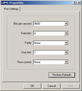
Figure 4-4 Setting communications parameters
Step 4: Click <OK>. The HyperTerminal dialogue box appears, as shown in Figure 4-5.

Figure 4-5 HyperTerminal window
In the HyperTerminal dialogue box, select [File/Properties]. The Properties dialog box appears. In the Properties dialog box, select the Settings tab, as shown in Figure 4-6. Select VT100 or Auto detect in the Emulation dropdown menu. Click <OK>.
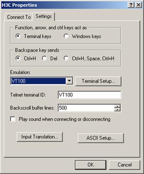
4.4 Booting the Switch
4.4.1 Verifying Installation before Power-up
Before powering up the switch, check that:
l Both the power cord and the grounding wire are correctly connected.
l Proper power supply is used.
l The console cable is correctly connected.
l The console terminal (or PC) has been started and the related parameters have been set on it.
4.4.2 Powering up the Switch
For the models in the S3600 series, the displayed Boot ROM information is similar. Following is the Boot ROM information displayed on the S3600-28TP-SI:
Starting......
***********************************************************
* *
* H3C S3600-28TP-SI BOOTROM, Version 320 *
* *
***********************************************************
Copyright(c) 2004-2007 Hangzhou H3C Technologies Co., Ltd.
Creation date : Apr 10 2007, 11:27:16
CPU type : BCM4704
CPU Clock Speed : 200MHz
BUS Clock Speed : 33MHz
Memory Size : 64MB
Mac Address : 000fcb004500
Press Ctrl-B to enter Boot Menu... 1
l By default, the system boots with fast startup mode. If you do not want to change it, ignore the message “Press Ctrl-B to Enter Boot Menu…”, the system boots automatically without entering the Boot Menu one seconds later and displays the following information:
Auto-booting...
Decompress Image..............................................................
...................................................................
...................................................................
...................................................................
...................................................................
...............................................OK!
Starting at 0x80100000...
User interface aux0 is available.
Press ENTER to get started.
l To change the startup mode to the full (normal) mode, press <Ctrl+B> within one seconds after the prompt “Press Ctrl-B to Enter Boot Menu…” appears. The program enters the Boot Menu.
BOOT MENU
1. Download application file to flash
2. Select application file to boot
3. Display all files in flash
4. Delete file from flash
5. Modify bootrom password
6. Enter bootrom upgrade menu
7. Skip current configuration file
8. Set bootrom password recovery
9. Set switch startup mode
0. Reboot
Enter your choice(0-9):
Press <9>. The following information appears:
The current mode is fast startup mode!
Are you sure to change it to full startup mode? Yes or No(Y/N)
Make sure you already understand that it takes a relative long time for the system to boot with full startup mode because it must perform some self-test operations.
Press <Y>. The following information appears:
Setting startup mode...done!
BOOT MENU
1. Download application file to flash
2. Select application file to boot
3. Display all files in flash
4. Delete file from flash
5. Modify bootrom password
6. Enter bootrom upgrade menu
7. Skip current configuration file
8. Set bootrom password recovery
9. Set switch startup mode
0. Reboot
Enter your choice(0-9):
Press <0>. The system reboots with full startup mode and displays the following information:
Starting......
***********************************************************
* *
* H3C S3600-28TP-SI BOOTROM, Version 320 *
* *
***********************************************************
Copyright(c) 2004-2007 Hangzhou H3C Technologies Co., Ltd.
Creation date : Apr 10 2007, 11:27:16
CPU type : BCM4704
CPU Clock Speed : 200MHz
BUS Clock Speed : 33MHz
Memory Size : 64MB
Mac Address : 000fcb004500
Press Ctrl-B to enter Boot Menu... 5
To enter the Boot Menu, press <Ctrl+B> within five seconds after the message “Press Ctrl-B to enter Boot Menu... 5” appears. If not, the system automatically boots and displays:
Auto-booting...
Decompress Image................................................................
..........................................................................
..........................................................................
..........................................................................
..........................................................................
..........................................................................
..........................................................................
............................OK!
Starting at 0x80100000...
Initialize LSJ1LTSE........................OK!
SDRAM fast selftest........................OK!
Flash fast selftest........................OK!
CPLD selftest..............................OK!
Switch chip selftest.......................OK!
PHY selftest...............................OK!
Please check port leds...............FINISHED!
User interface aux0 is available.
Press ENTER to get started.
The appearance of “Press ENTER to get started” indicates that the switch has completed its automatic boot.
Press <Enter>; the system displays:
<H3C>
You can configure the switch now.
& Note:
l If the specified host software does not exist, the switch will automatically choose currently valid host software to boot.
l A wide range of command views are available for H3C Series Switches. For more information on configuration commands and command line interfaces, refer to H3C S3600 Series Ethernet Switches Operation Manual and H3C S3600 Series Ethernet Switches Command Manual.
Chapter 5 Loading Boot ROM and Host Software
Switch software loading through serial ports in the past is time consuming and cannot be operated remotely. To address these problems, TFTP and FTP are used to allow software and file downloading through Ethernet ports. The following subsections describe how to load software and files in these two approaches.
5.1 Introduction to Loading Approaches
To load software remotely, use FTP or TFTP.
To load software at the local, use XModem at the Console port or TFTP/FTP at an Ethernet port.
& Note:
Ensure that the Boot ROM and host software versions that you download can work with each other.
5.2 File attribute in Boot ROM
5.2.1 Introduction to File Attribute
In Boot ROM, application files, configuration files, and Web files support three kinds of attributes: main, backup, and none, which are described in Table 5-1.
|
Attribute |
Usage |
Feature |
Identification |
|
main |
Indicates the main boot file, which is used by a device to boot. |
Only one application file, one configuration file, and one Web file in the Flash can have the main attribute. |
(*) |
|
backup |
Indicates a boot file with the backup attribute. When a device cannot boot with the main boot file, it will use the backup boot file to boot. |
Only one application file, one configuration file, and one Web file in the Flash can have the backup attribute. |
(b) |
|
none |
Indicates a file having neither the main attribute nor the backup attribute. |
— |
No special identification |
& Note:
l The suffixes of application, configuration, and Web files are app, cfg, and web respectively.
l A file can have both the main attribute and the backup attribute. Such a file is displayed with identification of (*b).
If you specify a file to have the main attribute when there is already a main boot file, the original main boot file will lose the main attribute, ensuring that only one application file, one configuration file, and one web file in the Flash have the main attribute. The same is true for the backup attribute.
Operations of a file are separate from those of the attributes. For example, when you delete a main boot file from the Flash, the main attribute of the file remains. If you download a valid file with the same name to the Flash, the new file will have the main attribute.
The file attribute feature is backward compatible. When you upgrade the Boot ROM of a device, the original default app boot file has the main attribute.
5.2.2 Impact of File Attributes on Downloading and Booting
I. Downloading
When you download an application, configuration, or Web file from the boot menu through TFTP or FTP, the device identifies the file by its suffix and checks the validity of the file if it is an app file. Then, the device displays a message for you to confirm if you want to set it as a boot file. You can set file attributes at prompt.
& Note:
If a downloaded file has the same name as that of an existing file in the Flash, the new file will overwrite the original one, while having the same attributes.
II. Booting
When a device boots, it first uses the application file with the main attribute. If the boot operation fails, the device selects the application file with the backup attribute to try again. If the boot operation fails again, the device displays an error message and repeats the above procedure.
& Note:
l If the device boots failed with an application file with main attribute, it will display an alert message.
l If the specified application file does not exist, the switch will automatically choose an existing valid application file to boot.
5.2.3 Setting the Attribute of a File
You can set the attribute of a file from the Boot menu.
The following takes an application file for example to describe the required steps:
I. Enter the Boot menu and input 2 to select “2. Select application file to boot” and enter the corresponding submenu.
1. Download application file to flash
2. Select application file to boot
3. Display all files in flash
4. Delete file from flash
5. Modify bootrom password
6. Enter bootrom upgrade menu
7. Skip current configuration file
8. Set bootrom password recovery
9. Set switch startup mode
0. Reboot
Enter your choice(0-9):2
Select application file to boot
1. set application files
2. set configuration files
3. set web files
0. return
Enter your choice(0-3):1
II. Set the attributes of application, configuration, or Web files as needed. In this example, enter 1 to select “1. set application files”.
File Number File Size(bytes) File Name
======================================================================
1(*) 4719134 S3600.bin
2(b) 3886308 S3600-2.bin
3 3886308 S3600-3.bin
Free Space: 2682880 bytes
(*)-with main attribute
(b)-with backup attribute
(*b)-with both main and backup attribute
Please input the file number to change:
III. Set the attribute of file 2 to main.
Please input the file number to change: 2
Please input the file attribute to change (main/backup): main
The attribute of S3600-1.bin is changed from main to none!!
When setting the attribute of a file, you can use the strings listed in the following table. The strings are case-insensitive.
Table 5-2 String to Input for the Attribute
|
Attribute |
String to input |
|
main |
m, ma, mai, or main |
|
backup |
b, ba, bac, back, backu, or backup |
If a file has neither the main attribute nor the backup attribute after you change the attributes of other files, the device will give the file the attribute of none and display an alert message.
IV. If you change the attribute of an application file to main, the device will display a message for you to confirm whether you want to boot the device immediately.
Do you want to run S3600-2.bin now? Yes or No(Y/N) y
If you enter y, the device will reboot immediately. If you enter n, the device will return to the [Select application file to boot] submenu.
5.3 Loading Software Locally
If your terminal is directly connected to the switch, you can load Boot ROM and host software locally. But before that, make sure they are correctly connected.
& Note:
The steps that you should take to load Boot ROM program and host software are the same, except that during Boot ROM program loading you need to press <Ctrl +U> after accessing the Boot ROM menu and will view different prompt information. Boot ROM loading procedures are described below for example.
5.3.1 Boot Menu
Starting......
***********************************************************
* *
* H3C S3600-28TP-SI BOOTROM, Version 320 *
* *
***********************************************************
Copyright(c) 2004-2007 Hangzhou H3C Technologies Co., Ltd.
Creation date : Apr 10 2007, 11:27:16
CPU type : BCM4704
CPU Clock Speed : 200MHz
BUS Clock Speed : 33MHz
Memory Size : 64MB
Mac Address : 000fcb004500
Press Ctrl-B to enter Boot Menu... 1
Press <Ctrl+B> as prompted. The system displays:
Password :
& Note:
To access the Boot Menu, press <Ctrl+B> within one seconds after the information “Press Ctrl-B to enter Boot Menu...” appears; otherwise the system starts to decompress the program. At this time if you want to access the Boot Menu, you need to restart the switch.
Input the correct Boot ROM password (no password is set by default). The system enters the following Boot Menu:
BOOT MENU
1. Download application file to flash
2. Select application file to boot
3. Display all files in flash
4. Delete file from flash
5. Modify bootrom password
6. Enter bootrom upgrade menu
7. Skip current configuration file
8. Set bootrom password recovery
9. Set switch startup mode
0. Reboot
Enter your choice(0-9):
5.3.2 Loading Software from Console Port Using XModem
I. Introduction to XModem
XModem is a file transfer protocol widely used for its simplicity and good performance. XModem transfers files through the Console port, supporting data packets of 128 bytes and 1 KB. With respect to reliability, it supports checksum, CRC, and the error packet retransmission mechanism. Normally, the maximum number of retransmission attempts is ten.
XModem transfer is completed by receiving and sending programs together. Receiving program initiates packet checking method negotiation by sending the negotiation character. If negotiation passes, the sending program starts packet transfer. Upon receipt of a complete packet, the receiving program checks it using the agreed-upon check method. If the check succeeds, the receiving program sends an acknowledgement character; if the check fails, it sends a reject character. Upon receipt of the acknowledgement, the sending program continues to send the next packet; upon receipt of the reject, it retransmits the packet.
II. Loading BootROM
Follow these steps to download the Boot ROM program:
Step 1: Enter <6> or <Ctrl + U> in the Boot Menu to access the Boot ROM loading menu shown below:
Bootrom update menu:
1. Set TFTP protocol parameter
2. Set FTP protocol parameter
3. Set XMODEM protocol parameter
0. Return to boot menu
Enter your choice(0-3):
Step 2: Enter <3> in the loading menu to download through XModem. The system displays the following download speed setting menu:
Please select your download baudrate:
1.* 9600
2. 19200
3. 38400
4. 57600
5. 115200
0. Return
Enter your choice (0-5):
Step 3: Choose an appropriate download baud rate. Enter <5> for example to download at 115200 bps. The system displays the following information:
Download baudrate is 115200 bps
Please change the terminal's baudrate to 115200 bps and select XMODEM protocol
Press enter key when ready
& Note:
You do not need to modify the HyperTerminal’s baud rate if you have chosen 9600 bps, and thus can skip Steps 4 through 6 and proceed to Step 7 directly. At this time, the system does not display the above information.
Step 4: Enter HyperTerminal’s [File/Properties] menu, as shown in Figure 5-1. Click <Configuration> in the popup dialog box, select the baud rate of 115200bps in the Console Port Configuration dialog box, as shown in Figure 5-2.

Figure 5-1 Properties dialog box

Figure 5-2 Console Port Configuration dialog box
Step 5: Click <Disconnect> to disconnect the HyperTerminal from the switch and then click <Call> to re-establish the connection, thus validating the baud rate setting.

Figure 5-3 <Disconnect> and <Call> buttons
& Note:
After changing terminal’s baud rate, you must disconnect and connect the terminal emulation program to validate the new configuration.
Step 6: Press <Enter> to start program loading. The system displays the following information:
Now please start transfer file with XMODEM protocol.
If you want to exit, Press <Ctrl+X>.
Loading ...CCCCCCCCCC
Step 7: Select [Transfer/Send File] in the HyperTerminal’s window, and in the popup dialog box similar to Figure 5-4 click <Browse>, select the software you need to download, and set the protocol to XModem.

Figure 5-4 Send File dialog box
Step 8: Click <Send>. The system displays Figure 5-5.

Figure 5-5 Sending File interface
Step 9: After completing loading, the system displays the following information:
Loading ...CCCCCCCCCC done!
& Note:
You do not need to reset the HyperTerminal’s baud rate and can skip the last step if you have chosen 9600 bps. In this case, the system does not display the above prompt message but “BootROM is updating now.....................................done!” instead.
Step 10: Reset HyperTerminal’s baud rate to 9600 bps with reference to Steps 5 and 6 described above. Then, press any key as prompted. The system will display the following information when it completes the loading.
Bootrom updating.....................................done!
III. Loading host software
Follow these steps to download host software of the switch:
Step 1: Select <1> in the Boot Menu. The system displays the following information:
1. Set TFTP protocol parameter
2. Set FTP protocol parameter
3. Set XMODEM protocol parameter
0. Return to boot menu
Enter your choice(0-3):3
Select <3>. The subsequent steps are the same as those for loading Boot ROM, except for the program to be downloaded in prompt messages.
5.3.3 Loading Software from an Ethernet Port Using TFTP
I. Introduction to TFTP
Trivial File Transfer Protocol is a TCP/IP protocol used for file transfer between clients and servers. It uses UDP to provide unreliable data stream transfer service.
II. Loading Boot ROM
Step 1: Select an Ethernet port on the switch for loading and connect it to the PC where the file to be downloaded is stored. (You must know PC’s IP address). Besides, connect the Console port on the switch to an external PC. This PC can be the same one that stores the file to be downloaded.
Step 2: Run the TFTP Server program on the PC connected to the Ethernet port, and specify the path for program loading.
![]() Caution:
Caution:
TFTP Server program is not provided with the H3C Series Switches.
Step 3: Run terminal emulation program on the PC that is connected to the Console port. Start the switch, access the Boot Menu, and then enter the download protocol menu.
To download the Boot ROM program, enter <6> or <Ctrl + U> to access the menu for Boot ROM downloading when the system displays: “Enter your choice(0-9):”
Bootrom update menu:
1. Set TFTP protocol parameter
2. Set FTP protocol parameter
3. Set XMODEM protocol parameter
0. Return to boot menu
Enter your choice(0-3):
Step 4: In the download protocol menu, press <1>to select TFTP protocol to download Boot ROM or host software. Press <Enter>. The system displays the following information:
Load File name
Switch IP address ¬(This address and the server IP address must be on the same network segment)
Server IP address ¬ (IP address of the PC where the file is stored)
Step 5: Input the TFTP parameter values and press <Enter>. The system displays the following information:
Are you sure to update your bootrom?Yes or No(Y/N)
Step 6: Press <Y> to start file downloading and <N> to return to the program downloading menu. Suppose you press <Y> and then <Enter>. The system starts Boot ROM program downloading and automatically starts Boot ROM loading. After finishing loading, it displays the following information:
Loading........................................done
Bootrom updating..........done!
III. Loading host software
Follow these steps to download host software of the switch.
Step 1: Select <1> in the Boot Menu. The system displays the following information:
1. Set TFTP protocol parameter
2. Set FTP protocol parameter
3. Set XMODEM protocol parameter
0. Return to boot menu
Enter your choice(0-3):3
Select <1>. The subsequent steps are the same as those for loading Boot ROM, except for the program to be downloaded in prompt messages.
5.3.4 Loading Software from an Ethernet Port Using FTP
I. Introduction to FTP
With an Ethernet port, you can also use the switch as the FTP server or client to download or configuration files. The following subsections describe how to load software by using the switch as the FTP client for example.
II. Loading Boot ROM
Step 1: Select an Ethernet port on the switch for loading and connect it to the PC where the file to be downloaded is stored. (You must know PC’s IP address). Besides, connect the Console port on the switch to an external PC. This PC can be the same one that stores the file to be downloaded.
Step 2: Run the FTP Server program on the PC that is connected to the Ethernet port, and specify the path for program loading.
Step 3: Run terminal emulation program on the PC connected to the Console port. Start the switch, access the Boot Menu, and then enter the download protocol menu.
To download the Boot ROM program, enter <6> or <Ctrl + U> to access the menu for Boot ROM downloading when the system displays: “Enter your choice(0-9):”
Bootrom update menu:
1. Set TFTP protocol parameter
2. Set FTP protocol parameter
3. Set XMODEM protocol parameter
0. Return to boot menu
Enter your choice(0-3):
Step 4: In the download protocol menu, press <2> to select FTP protocol to download Boot ROM and host software. Press <Enter>. The system displays the following information:
Load File name
Switch IP address ¬(This address and the server IP address must be on the same network segment)
Server IP address ¬(IP address of the PC that stores the file)
FTP User Name
FTP User Password
Step 5: Input the FTP parameter values and press <Enter>. The system displays:
Are you sure to update your bootrom?Yes or No(Y/N)
Step 6: Press <Y> to start file downloading and <N> to return to the program downloading menu. Suppose you press <Y> and then <Enter>. The system starts program downloading and upon its completion, starts writing to Flash. After completing the writing operation, the system displays:
Loading........................................done
Bootrom updating..........done!
III. Loading host software
Follow these steps to download host software:
Step 1: Select <1> in the Boot Menu. The system displays:
1. Set TFTP protocol parameter
2. Set FTP protocol parameter
3. Set XMODEM protocol parameter
0. Return to boot menu
Enter your choice(0-3):3
Select <2>. The subsequent steps are the same as those for loading Boot ROM, except for the program to be downloaded in prompt messages.
5.4 Loading Software Remotely
If your terminal is connected to the switch by a network, you can load Boot ROM and host software remotely.
5.4.1 Loading Software Remotely Using FTP
Run FTP server on a local PC, provided you have configured username and password and have set the correct file directory. Suppose IP address of the PC is 10.10.110.1. Telnet to the switch and FTP the host program to the switch.
Provided that the host program is SWITCH.bin and the Boot ROM program is SWITCH.btm, you can take these steps after telneting to the switch.
Step 1: FTP the software to the switch.
<H3C> ftp 10.10.110.1
Trying ...
Press CTRL+K to abort
Connected.
220 WFTPD 2.0 service (by Texas Imperial Software) ready for new user
User(none):lyt
331 Give me your password, please
Password:
230 Logged in successfully
[ftp] get SWITCH.bin SWITCH.bin
[ftp] get SWITCH.btm SWITCH.btm
[ftp] bye
Step 2: Load Boot ROM.
<H3C> boot bootrom SWITCH.btm
please wait ...
Bootrom is updated!
Step 3: Load the host software.
<H3C> boot boot-loader SWITCH.bin
<H3C> display boot-loader
The app to boot at the next time is: flash:/SWITCH.bin
<H3C> reboot
& Note:
l Power disconnection must be prevented during the loading process.
l The configurations that you just make cannot survive a reboot. Make sure you have saved them before you have the system reboot.
l To validate the downloaded Boot ROM and host software, you must reboot the switch.
l In case of inadequate Flash memory space, you can delete some of the program files in Flash, those that are no longer in use for example, after completing Boot ROM loading. Then FTP the host program to the switch.
5.4.2 Loading Software Remotely Using TFTP
TFTP is similar to FTP in remote software downloading. But with TFTP, the switch can only be used as the client to download software to its Flash Memory from the TFTP server. After that, the remaining steps are the same as remote loading using FTP.
Chapter 6 Maintenance and Troubleshooting
6.1 Dealing with Loading Failures
If software loading fails, the system operates with the original version.
To address the failure cause, take these steps:
1) Check that the physical ports are correctly and securely connected. If they are not, reconnect them correctly and restart loading.
2) Check information about the loading procedures for input errors on the HyperTerminal.
l If XModem is used, check that you have reset the baud rate of the HyperTerminal to 9600 bps after loading the software with another baud rate.
l If TFTP is used, check that you have correctly specified the TFTP parameters: server and switch IP addresses; name of the software to be loaded; and path for the TFTP server to operate on program files.
l If FTP is used, check that you have correctly specified the FTP parameters: server and switch IP addresses; name of the software to be loaded; and username and password.
3) Contact your sales agent for help if you cannot address the problem after taking the preceding two steps.
6.2 Dealing with Password Loss
6.2.1 Dealing with User Password Loss
If you lost your user password, enter the Boot Menu first:
BOOT MENU
1. Download application file to flash
2. Select application file to boot
3. Display all files in flash
4. Delete file from flash
5. Modify bootrom password
6. Enter bootrom upgrade menu
7. Skip current configuration file
8. Set bootrom password recovery
9. Set switch startup mode
0. Reboot
Enter your choice(0-9):
Select <7> and restart the switch. After that, the system will skip the configuration file.
6.2.2 Recovering the Boot ROM Password
Contact your sales agent for help.
6.3 Dealing with Power System Failures
You can know whether the power system has failed by reading the PWR LED on the front panel. If the power system is operating normally, the PWR LED is ON. If not, check that:
l The switch power cord is correctly connected.
l The power source can work with the switch.
6.4 Dealing with Configuration System Failures
If the switch is operating normally after it is powered up, it displays the start-up information on the console terminal. If the configuration system has failed, it displays illegible characters or nothing at all.
I. No information on the terminal
Take these steps to address the problem:
1) Check that:
l The power system is operating normally.
l The console cable is connected correctly.
2) Check that the console cable is in good condition and the terminal (HyperTerminal for example) parameter settings are correct.
II. Illegible characters on the terminal
Make sure you have set on your terminal (HyperTerminal):
Bits per second: 9600
Data bit: 8
Parity check: none
Stop bit: 1
Flow control: none
Terminal emulation: VT100
Reconfigure the parameters if their values are different.