- Table of Contents
- Related Documents
-
| Title | Size | Download |
|---|---|---|
| 03-Security Operation | 1 MB |
Chapter 1 Network Security Overview
1.1 Introduction to the Network Security Features Provided by CMW
1.2 Hierarchical Command Line Protection
1.4 Packet Filter and Firewall
1.5 Security Authentication for Route Information Exchange
Chapter 2 AAA and RADIUS/HWTACACS Protocol Configuration
2.1.2 Introduction to the RADIUS Protocol
2.1.3 Introduction to the HWTACACS Protocol
2.2.1 Creating an ISP Domain and Setting the Related Attributes
2.2.2 Creating a Local User and Setting the Related Attributes
2.3 Configuring the RADIUS Protocol
2.3.1 Creating a RADIUS Scheme
2.3.2 Configuring RADIUS Authentication/Authorization Servers
2.3.3 Configuring RADIUS Accounting Servers and Related Attributes
2.3.4 Setting the Shared Key for RADIUS Packet Encryption
2.3.5 Setting the Maximum Number of RADIUS Request Attempts
2.3.6 Setting the Supported RADIUS Server Type
2.3.7 Setting the State of RADIUS Servers
2.3.8 Setting the Username Format Acceptable to RADIUS Servers
2.3.9 Setting the Unit of Data Flows Destined for RADIUS Servers
2.3.10 Configuring an IP Address for the NAS to Use as the Source IP Address of RADIUS Packets
2.3.11 Setting RADIUS Server Timers
2.3.12 Configuring to Send a Trap Packet When the RADIUS Server Goes Down
2.3.13 Configuring Local RADIUS Authentication Server
2.4 Configuring HWTACACS Protocol
2.4.1 Creating a HWTACACS Scheme
2.4.2 Configuring TACACS Authentication Servers
2.4.3 Configuring TACACS Authorization Servers
2.4.4 Configuring TACACS Accounting Servers and Related Attributes
2.4.5 Configuring an IP Address for the NAS to Use as the Source IP Address of HWTACACS Packets
2.4.6 Setting a Key for TACACS servers
2.4.7 Setting the Username Format Acceptable to TACACS Servers
2.4.8 Setting the Unit of Data Flows Destined for TACACS Servers
2.4.9 Setting TACACS Server Timers
2.5 Configuring TACACS to Support Super Authentication
2.5.1 Right Switching in Super Authentication
2.5.2 Setting Super Authentication Mode
2.5.3 Setting Super Authentication Scheme
2.6 Displaying and Debugging AAA and RADIUS and HWTACACS Protocols
2.7 AAA, RADIUS and HWTACACS Protocol Configuration Example
2.7.1 Authentication and Accounting for Telnet/SSH Users Using a RADIUS Server
2.7.2 Local Authentication for FTP/Telnet Users
2.8 Troubleshooting AAA, RADIUS and HWTACACS Protocols
2.8.1 Troubleshooting the RADIUS Protocol
2.8.2 Troubleshooting the HWTACACS Protocol
3.2.2 Configuring an Advanced ACL
3.2.3 Configuring an Interface-Based ACL
3.2.4 Configuring a MAC-Based ACL
3.2.5 Adding a Description to an ACL
3.2.6 Adding a Comment to an ACL Rule
3.3.1 Creating/Removing a Time Range
3.4 Displaying and Debugging ACL
3.5 Typical Configuration Examples of ACL
4.2.1 Many-to-Many Address Translation and Address Translation Control
4.2.3 Static Network Segment Address Translation
4.2.4 Bidirectional Network Address Translation
4.2.7 NAT Application Level Gateway
4.2.8 Limiting the Maximum Number of TCP Connections through NAT
4.3.1 Configuring Address Pool
4.3.3 Configure Bidirectional NAT Table
4.3.4 Configuring Internal Server
4.3.6 Configuring Domain Name Mapping
4.3.7 Configuring Address Translation Lifetimes
4.3.8 Configuring NAT to Limit the Maximum Number of TCP Connections
4.4 Displaying and Debugging NAT
4.6 Troubleshooting NAT Configuration
Chapter 5 Firewall Configuration
5.1.2 Application Specific Packet Filter
5.2.1 Enabling or Disabling Firewall
5.2.2 Setting the Default Filtering Mode of Firewall
5.2.3 Enabling Packet Filter Fragment Detection
5.2.4 Configuring Upper/Lower Threshold of Fragment Detection
5.2.5 Applying ACL on the Interface
5.2.6 Displaying and Debugging Packet Filter
5.2.7 Packet Filter Configuration Example
5.2.8 Configuration Example of Fragment Filtering Through Packet Filter
5.3.4 Applying ASPF Policy to Specified Interface
5.3.5 Setting the Session Timeout Values
5.3.6 Configuring ASPF with Session Logging
5.3.7 Configuring Port Mapping
5.3.8 Displaying and Debugging ASPF
5.3.9 Cautions about ASPF Configuration
5.3.10 ASPF Configuration Example
5.4 Configuring Virtual Firewall
5.4.2 Binding an Interface to a VPN Instance
5.4.3 Configuring the Limitation of Virtual Firewall Resources
5.4.4 Displaying and Debugging Virtual Firewall
5.4.5 Virtual Firewall Configuration Example
5.5.1 Introduction to Black List
5.5.3 Displaying and Debugging Black List
5.5.4 Black List Configuration Example
5.6 MAC and IP Address Binding
5.6.1 Introduction to MAC and IP Address Binding
5.6.2 Configuring MAC and IP Address Binding
5.6.3 Displaying and Debugging MAC and IP Address Binding
5.6.4 MAC and IP Address Binding Configuration Example
5.7 Security Zone Configuration
5.7.1 Introduction to Security Zone
5.7.2 Configuring Security Zone
Chapter 6 Transparent Firewall
6.1 Transparent Firewall Overview
6.1.1 Obtaining a MAC Address Table
6.1.2 Forwarding and Filtering
6.2 Configuring Transparent Firewall
6.2.1 Configuring Firewall Mode
6.2.2 Configuring System IP Address
6.2.3 Enabling/Disabling Dynamic ARP Learning
6.2.4 Configuring Handling Approach for the Packets with Unknown MAC Address
6.2.5 Configuring MAC Address-Based ACLs
6.2.6 Applying MAC Address-Based ACL to the Interface
6.2.7 Configuring Aging Time of the MAC Forwarding Table
6.2.8 Defining Allowed Packet Types
6.2.9 Configuring VLAN ID Transparent Transmission
6.3 Displaying and Debugging Transparent Firewall
6.4 Transparent Firewall Configuration Example
Chapter 7 Web and E-mail Filtering
7.1 Introduction to Web and E-mail Filtering
7.2.1 Configuring Web Address Filtering
7.2.2 Configuring Web Content Filtering
7.2.3 Configuring SQL Attack Prevention
7.3 Configuring E-mail Filtering
7.3.1 Configuring E-mail Address Filtering
7.3.2 Configuring E-mail Subject Filtering
7.3.3 Configuring E-mail Content Filtering
7.3.4 Configuring E-mail Attachment Filtering
7.3.5 Displaying and Debugging E-mail Filtering
Chapter 8 Attack Prevention and Packet Statistics
8.1 Overview of Attack Prevention and Packet Statistics
8.1.1 Introduction to Attack Prevention
8.1.2 Classes of Network Attacks
8.1.3 Typical Examples of Network Attacks
8.1.4 Introduction to Packet Statistics Analysis
8.2 Configuring Attack Prevention
8.2.1 Enabling/Disabling ARP Flood Attack Prevention
8.2.2 Configuring ARP Spoofing Attack Prevention
8.2.3 Enabling/Disabling the IP Spoofing Attack Prevention Function
8.2.4 Enabling/Disabling the Land Attack Prevention Function
8.2.5 Enabling/Disabling the Smurf Attack Prevention Function
8.2.6 Enabling/Disabling the WinNuke Attack Prevention Function
8.2.7 Enabling/Disabling the Fraggle Attack Prevention Function
8.2.8 Enabling/Disabling Frag Flood Attack Prevention
8.2.9 Enabling/Disabling the SYN Flood Attack Prevention Function
8.2.10 Enabling/Disabling the ICMP Flood Attack Prevention Function
8.2.11 Enabling/Disabling the UDP Flood Attack Prevention Function
8.2.12 Enabling/Disabling the ICMP Redirect Packet Control Function
8.2.13 Enabling/Disabling the ICMP Unreachable Packet Control Function
8.2.14 Enabling/Disabling the IP Sweep Attack Prevention Function
8.2.15 Enabling/Disabling the Port Scan Attack Prevention Function
8.2.16 Enabling/Disabling the Attack Prevention Function of the IP Packet Carrying Source Route
8.2.17 Enabling/Disabling Attack Prevention for Route Record Options
8.2.18 Enabling/Disabling the Tracert Packet Control Function
8.2.19 Enabling/Disabling Ping of Death Prevention Function
8.2.20 Enabling/Disabling the Teardrop Attack Prevention Function
8.2.21 Enabling/Disabling the TCP Flag Validity Detection Function
8.2.22 Enabling/Disabling the IP Fragment Packet Detection Function
8.3 Setting the Warning Level in Monitoring the Number and Rate of Connections
8.3.1 Enabling/Disabling the Oversized ICMP Packet Control Function
8.4 Configuring System-Based Statistics
8.4.1 Enabling/Disabling the System-Based Statistics Function
8.4.2 Configuring the System-Based Connection Count Monitoring
8.4.3 Configuring Alarm Detection for Abnormal System Packet Rate
8.5 Configuring Zone-Based Statistics
8.5.1 Enabling/Disabling the Zone-Based Statistics Function
8.5.2 Configuring the Zone-Based Connection Count Monitoring
8.5.3 Configuring the Zone-Based Connection Rate Monitoring
8.6 Configuring IP-Based Statistics
8.6.1 Enabling/Disabling the IP-Based Statistics Function
8.6.2 Configure the IP-Based Connection Count Monitoring Function
8.6.3 Configuring the IP-Based Connection Rate Monitoring Function
8.7 Displaying and Debugging Attack Prevention and Packet Statistics
8.7.1 Displaying and Debugging Attack Prevention
8.7.2 Displaying and Debugging Packet Statistics
8.8.1 Configuring Mail Triggering Time
8.8.2 Configuring Mail Addresses
8.8.3 Displaying and Debugging SMTP Client Configuration
8.9.1 Configuring a DNS Server
8.9.3 Displaying and Debugging DNS Client Configuration
8.10 Attack Prevention and Packet Statistics Configuration Examples
8.10.1 Enabling the Land Attack Prevention Function
8.10.2 Enabling the SYN Flood Attack Prevention Function
8.10.3 Enabling the Address Scanning Attack Prevention Function
8.10.4 Enabling the Zone-Based Connection Count Monitoring Function
8.10.5 Displaying Statistics Information of Specified IP Address
8.11 Attack Prevention Troubleshooting
9.1 Introduction to IDS Cooperation
9.2 Configuring IDS Cooperation
9.2.1 Issuing IDS-Cooperation ACL Rules to Interfaces
9.2.2 Displaying and Debugging IDS Cooperation
9.3 IDS Configuration Examples
10.2.1 Configuring Syslog Log Output Format
10.2.2 Configuring the Sweep Time for the Syslog Log Buffer
10.2.3 Configuring the Log Redirection for the Information Center
10.3 Binary-Flow Log Configuration
10.3.1 Enabling/Disabling Binary-Flow Log Output in Interzone
10.3.2 Configuring Host Address and Port of Receiving Binary-Flow Log
10.5 Log Configuration Example
10.5.1 Outputting Attack Prevention Log to Host
10.5.2 Outputting Binary-Flow Log to Host
Chapter 1 Network Security Overview
& Note:
All the contents below are about SecBlade cards, so the commands in this manual are executed in views corresponding to SecBlade cards instead of the other series switches.
1.1 Introduction to the Network Security Features Provided by CMW
SecBlade must be able to withstand malicious attacks from the public network. On the other hand, the accidental but destructive access may also result in significant performance decrease and even the operation failure.
CMW provides the following network security characteristics:
l Authentication, authorization and accounting (AAA) services based on Remote Authentication Dial-In User Service (RADIUS). AAA can provide authentication, authorization, and accounting services on users for preventing illegal access.
l Authentication protocol that supports CHAP and PAP authentication on PPP line.
l Packet filter implemented through access control list (ACL) which specifies the type of packets that the SecBlade will permit or deny.
l Application specific packet filter (ASPF), or status firewall. ASPF is an advanced communication filtering approach that checks the application layer information and monitors the status of connection-oriented application layer protocols, maintains the status information of each connection, and dynamically makes decision on whether to permit or deny a packet.
l IP security (IPSec), which guarantees the privacy, integrity and validity of packets while being transmitted on the Internet through encryption and data source authentication on the IP layer.
l Internet key exchange (IKE) that provides the services of key exchange through auto-negotiation and establishment of the security association (SA) to simplify the use and management of IPSec.
l Event log, which is used to record system security events and trace illegal access in real time.
l Address translation provided by NAT Gateway (GW), which separates the public network from the intranet, makes the IP addresses of the internal devices unknown to the public network, and hence prevents the attacks from the public network.
l Dynamic routing protocol authentication that ensures reliable route information to be exchanged.
l Hierarchical view protection, which classifies users into four levels that are assigned with different configuration rights. A low-level user cannot enter the view of a higher level.
The following chapters describe how to configure AAA and RADIUS, user password, firewall and packet filtering. Refer to the VPN part of this manual for IPSec/IKE configuration; refer to NAT Configuration for address translation configuration; refer to the Routing Protocol part of this manual for dynamic routing protocol authentication.
1.2 Hierarchical Command Line Protection
The system command lines are protected in a hierarchical way. In this approach, the command lines are divided into four levels: visit, monitor, system, and manage. You are unable to use the corresponding levels of commands unless you have provided the correct login password.
1.3 RADIUS-Based AAA
AAA is used for user access management. It can be implemented via multiple protocols but the AAA discussed here is based on RADIUS.
AAA provides:
l Hierarchical user management. Generally, users are allowed to perform the operations like managing and maintaining the system configuration data, and monitoring and maintaining the device. These operations are crucial to the normal operation of the system. Therefore, it is necessary to classify the users into different levels and grants each with specific rights. In this case, a low-level user can only perform some viewing operations, while only a high-level user can modify data, maintain devices, and perform some other sensitive operations.
l PPP authentication. With it, username/password authentication will be performed before the setup of a PPP connection.
l PPP address management and allocation. When setting up a PPP connection, the system may assign the pre-specified IP address to the PPP user.
The next chapter will cover the details of RADIUS protocol and its configurations, user password configuration, and PPP user address configuration. For PPP authentication protocols, refer to the User Access part of this manual.
1.4 Packet Filter and Firewall
1.4.1 Firewall Concept
The firewall can prevent unauthorized or unauthenticated users on the Internet from accessing a protected network while allowing the users on the internal network to access web sites on the Internet and send/receive E-mails. It can also work as an Internet access control GW by permitting only some particular users in an organization to access the Internet.
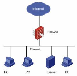
Figure 1-1 A firewall separating the intranet from the Internet
Apart from connecting the Internet, the firewall can also protect the mainframe and crucial resources (like data) on the intranet of the organization. Access to the protected data should be permitted by the firewall first, even if the access is initiated from the organization.
An external network user must pass through the firewall before it can access the protected network resources. Likewise, an intranet user must pass through the firewall before it can access the external network resources. Thus, the firewall plays the role as a “guard” and discards the denied packets.
1.4.2 Firewall Classification
Normally, firewalls are classified into two categories: network layer firewalls and application layer firewalls. Network layer firewalls mainly obtain the information of the packet header, such as protocol, source address, destination address, and destination port. Alternatively, they can directly obtain a segment from the packet header. The application layer firewalls, however, analyze the whole information traffic.
Firewalls are generally divided into the following categories:
l Application gateway: It verifies the application layer of all packets. Take a File Transfer Protocol (FTP) application GW as an example. From the perspective of the Client, the FTP GW is an FTP server; however, from the perspective of the Server, it is an FTP client. All the FTP packets must pass through this FTP GW.
l Circuit-Level Gateway: The term "circuit” refers to Virtual Circuit (VC). Before a TCP or UDP connection or a VC is opened, the session reliability must be verified. Packet transmission is allowed only after a valid handshake procedure is accomplished. After the setup of a session, the session information is stored in a table of valid connections maintained by the firewall. A packet can be permitted only if its session information matches an entry in the table. After the session is terminated, the session entry will be deleted from the table. The circuit-level GW authenticates a connection at the session layer. If the authentication is passed, any application can apply through the connection. Take FTP as an example. A circuit-level GW only authenticates an FTP session at the TCP layer at the beginning of the session. If the authentication is passed, all the data can be transmitted through this connection until the session is terminated.
l Packet filter: The firewall filters each packet based on the items that specified by the user. For example, the firewall compares the source and destination address of packets with the defined rules for a match. A packet filter neither considers the session status, nor analyzes the data. If the user specifies that the packets carrying port number 21 or a port number no less than 1024 are permitted, all the packets matching the rule can pass through the firewall. If the rules are specified based on actual applications, large numbers of malicious packets can be filtered out.
l Network Address Translation (NAT), also called address proxy, which makes it possible for a private network to access the external network. The NAT mechanism is to substitute the external network address and port number of SecBlade for that of a host on the private network and vice versa. In other words, it is the translation between <Private address + Port number> and <Public address + Port number>. The private address discussed here refers to the internal network or host address, and the public address refers to a globally unique IP address on the Internet. Internet Assigned Number Authority (IANA) provisioned that that the following IP address ranges are reserved for private addresses:
10.0.0.0 to 10.255.255.255
172.16.0.0 to 172.31.255.255
192.168.0.0 to 192.168.255.255
In other words, the addresses in these three ranges will be used inside organizations or companies rather than being assigned as Internet addresses. A company can select a proper network address range by taking the future expansion of internal hosts and networks into consideration. The internal network addresses of different companies can be the same. However, it may cause chaos if a company uses network addresses from a network segment range other than the three ranges given above. NAT allows internal hosts to access the Internet resources while keeping their “privacy”.
1.4.3 Packet Filter
I. Function
Generally, a packet filter filters IP packets. For the packets that the SecBlade will forward, the packet filter will first obtain the header information of each packet, including upper protocol carried by the IP layer, source and destination addresses, and source and destination port numbers of the packet. Then, the packet filter compares the above elements with the preset rules to determine whether the packet should be forwarded or discarded.
Figure 1-2 illustrates the elements that a packet filter uses for decision making (on IP packets), given the upper layer carried by IP is TCP/UDP.

Figure 1-2 Packet filtering elements
Most packet filter systems do not take any operation on data itself or make content-based filtering.
II. ACL
Before the system can filter the packets, you should configure ACL rules to specify which type of packets should be allowed or denied.
A user should configure an ACL according to the security policy and apply it to a specified interface or all the interfaces on the device. Then, the SecBlade checks all the packets received by the specified interface or all the interfaces based on the ACL, and then forwards or discards the packets matching the rules. In this way, the SecBlade functions as a firewall.
1.5 Security Authentication for Route Information Exchange
The SecBlade card operates based on the maintenance of the route forwarding table, which is implemented by dynamic route information exchange among neighboring routers.
I. Necessity of implementing security authentication for route information exchange
As the neighboring routers on a network need to exchange enormous route information, some unreliable routers may attack other network devices. Enabled with the route authentication function, the SecBlade card will be able to authenticate the route updates received from neighboring routers, and hence will receive only the reliable route information.
II. Authentication Implementation
The routers exchanging route information share the same key that is sent along with the route information packets. Upon receiving the route information, the routers will authenticate the packets, and verify the key carried by the packets. If the key carried by the packets is the same as the shared key, the packets will be accepted; otherwise, they will be discarded.
Authentication can be implemented through simple text authentication and MD5 authentication. The former sends keys in plain text providing lower security, whereas the latter sends encrypted keys providing higher security.
Chapter 2 AAA and RADIUS/HWTACACS Protocol Configuration
2.1 Overview
2.1.1 Introduction to AAA
Authentication, Authorization and Accounting (AAA) provides a framework designed to configure a set of three security functions in a consistent manner.
The network security mentioned here refers to access control and it includes:
l Which users can access the network server?
l Which services can the authorized users enjoy?
l How to keep accounts for the users who are using network resources?
Accordingly, AAA provides the following services:
I. Authentication
For authentication, the following methods are supported:
l None authentication: All users are trusted and are not verified. Generally, this method is not recommended.
l Local authentication: User profiles (including username, password, and attributes) are stored on the broadband access server (BAS). Local authentication features high speed but low cost; the information that can be stored in this approach is however limited depending on hardware.
l Remote authentication: RADIUS and HWTACACS protocols are supported for remote authentication. In this approach, the BAS acts as the client to communicate with the RADIUS or TACACS authentication server. For RADIUS, you can use standards-based RADIUS protocol or H3C extended RADIUS protocol to complete authentication in conjunction with devices like iTELLIN/CAMS.
II. Authorization
For authorization, the following methods are supported:
l Direct authorization: All users are trusted and directly authorized.
l Local authorization: Users are authorized according to the relevant attributes of the local user accounts configured on the BAS.
l HWTACACS authorization: Users are authorized by the TACACS server.
l If-authenticated authorization: Users are authorized after they are authenticated in any method other than none authentication.
l RADIUS authorization following successful authentication: With RADIUS, users are authorized only after they pass authentication. In other words, you cannot perform RADIUS authorization without authentication.
III. Accounting
For accounting, the following methods are supported:
l None accounting: Users are not accounted.
l Remote accounting: Users are accounted remotely through the RADIUS server or TACACS account server.
& Note:
Currently, the SecBlade supports accounting for PPP users and Telnet users only, but it does not provide real time accounting for Telnet users.
AAA usually utilizes a client/server model, where the client controls user access and the server stores user information. The framework of AAA thus has a high scalability and centralized management. Being a management framework, AAA can be implemented using multiple protocols. In CMW, for example, AAA is implemented based on the RADIUS protocol or HWTACACS protocol.
2.1.2 Introduction to the RADIUS Protocol
I. What is RADIUS
Remote authentication dial-In user service (RADIUS) is an information exchange protocol in a distributed client/server model designed for preventing a network from being accessed illegally. It is often used in network environments where both high security and remote access are required, for example, to manage a large number of dispersed dial-in users that use serial ports and modems. The RADIUS system is an important auxiliary part of the Network Access Server (NAS).
The RADIUS service involves three components:
l Protocol: Based on the UDP/IP layer, RFC2865 and 2866 define the RADIUS frame format and the message transfer mechanism, and use UDP port 1812 as the authentication port and UDP port 1813 as the accounting port.
l Server: RADIUS server runs on the computer or workstation at the center, and maintains authentication and network access information.
l Client: RADIUS client is located at the Network Access Server (NAS) side anywhere in the network.
As the RADIUS client, the NAS (a switch or a router) is responsible for transferring user information to a designated RADIUS server and taking actions based on the response from the server (such as connecting or disconnecting users). The RADIUS server receives user connection requests, authenticates users, and returns the required information to the NAS.
In general, the RADIUS server maintains three databases, namely, users, clients and dictionary, as shown in the following figure. The users database stores user information such as username, password, applied protocols, and IP address; the clients database stores information about RADIUS clients such as shared key; and the dictionary database stores the information for interpreting RADIUS protocol attributes and their values.

Figure 2-1 RADIUS server components
In addition, the RADIUS server can act as the client of other AAA servers to provide proxy authentication or accounting service. The RADIUS server supports authentication in many ways, such as PPP-based PAP, CHAP and UNIX-based login.
II. Basic message exchange procedure in RADIUS
In most cases, user authentication using a RADIUS server involves the proxy function of devices like NAS. Transactions between the RADIUS client and the RADIUS server are authenticated through a shared key, and user passwords are transferred in cipher text across the network for enhanced security. The RADIUS protocol combines the authentication and authorization processes together by sending authorization information in the authentication response message. See the following figure.

Figure 2-2 Basic message exchange procedure in RADIUS
Following is how RADIUS operates:
1) The user enters the username and password.
2) Having received the username and password, the RADIUS client sends an authentication request (Access-Request) to the RADIUS server.
3) The RADIUS server compares the received user information against that in the Users database. If the authentication succeeds, it sends back an authentication response (Access-Accept) with user right. If the authentication fails, it returns an Access-Reject message.
4) The RADIUS client determines to permit the user based on the received authentication results. If so, the RADIUS client sends a start accounting request (Accounting-Request) to the RADIUS server, with the value of Status-Type being start.
5) The RADIUS server returns a start-accounting response (Accounting-Response).
6) The RADIUS client sends a stop-accounting request (Accounting-Request) to the RADIUS server, with the value of Status-Type being stop.
7) The RADIUS server returns a stop-accounting response (Accounting-Response).
III. RADIUS packet format
RADIUS transfers messages in UDP packets, and leverages timer, retransmission and primary/secondary mechanisms to ensure smooth message exchange between the RADIUS server and the RADIUS client. The following figure shows the RADIUS packet format.

Figure 2-3 RADIUS packet format
The identifier field is used for matching request packets against response packets. It varies with the attribute field and is up on the receiving of valid response packets. However, it keeps unchanged during retransmission.
The 16-byte authenticator field is used to authenticate the requests transmitted back from the RADIUS server. It also applies to the password hidden algorithm. There are two kinds of authenticators: request authenticator and response authenticator.
l Request authenticator is the random code of 16 bytes in length.
l Response authenticator is the operation result of applying the MD5 algorithm to code, identifier, request authenticator, length, attribute and shared-key.
1) The code field determines the type of a RADIUS packet, as shown in the following table.
|
Code |
Packet type |
Description |
|
1 |
Access-Request |
The packet carries user information and flows from the client to the server to help the client determine whether the user can access the network. In this packet, User-Name is required; NAS-IP-Address, User-Password, and NAS-Port are optional. |
|
2 |
Access-Accept |
The packet flows from the server to the client. If all the attribute values carried in the Access-Request packet are acceptable, the server allows the user to pass authentication and sends back an Access-Accept response. |
|
3 |
Access-Reject |
The packet flows from the server to the client. If any attribute value carried in the Access-Request packet is unacceptable, the server denies the user and sends back an Access-Reject response. |
|
4 |
Accounting-Request |
The packet carries user information and flows from the client to the server. The server can determine whether to start accounting according to the Acct-Status-Type attribute. The attributes carried in this type of packet are basically the same as those carried by an Access-Request packet. |
|
5 |
Accounting-Response |
The packet flows from the server to the client, notifying the client that the server has received the Accounting-Request packet and has recorded accounting information. The packet carries such information as number of input/output bytes, number of input/output packets, and session duration. |
2) The attribute field contains authentication, authorization, and accounting information, and provides detailed configuration of a request or response packet. This field is represented by the triplet of type, length and value. The following table lists the standard attribute values defined by RFC:
|
Type |
Attribute type |
Type |
Attribute type |
|
1 |
User-Name |
23 |
Framed-IPX-Network |
|
2 |
User-Password |
24 |
State |
|
3 |
CHAP-Password |
25 |
Class |
|
4 |
NAS-IP-Address |
26 |
Vendor-Specific |
|
5 |
NAS-Port |
27 |
Session-Timeout |
|
6 |
Service-Type |
28 |
Idle-Timeout |
|
7 |
Framed-Protocol |
29 |
Termination-Action |
|
8 |
Framed-IP-Address |
30 |
Called-Station-Id |
|
9 |
Framed-IP-Netmask |
31 |
Calling-Station-Id |
|
10 |
Framed-Routing |
32 |
NAS-Identifier |
|
11 |
Filter-ID |
33 |
Proxy-State |
|
12 |
Framed-MTU |
34 |
Login-LAT-Service |
|
13 |
Framed-Compression |
35 |
Login-LAT-Node |
|
14 |
Login-IP-Host |
36 |
Login-LAT-Group |
|
15 |
Login-Service |
37 |
Framed-AppleTalk-Link |
|
16 |
Login-TCP-Port |
38 |
Framed-AppleTalk-Network |
|
17 |
(unassigned) |
39 |
Framed-AppleTalk-Zone |
|
18 |
Reply_Message |
40-59 |
(reserved for accounting) |
|
19 |
Callback-Number |
60 |
CHAP-Challenge |
|
20 |
Callback-ID |
61 |
NAS-Port-Type |
|
21 |
(unassigned) |
62 |
Port-Limit |
|
22 |
Framed-Route |
63 |
Login-LAT-Port |
The RADIUS protocol is extensible. The No. 26 attribute (Vender-Specific) defined in the protocol allows you to define an extended attribute, as shown in the following figure.

Figure 2-4 A RADIUS packet segment containing the extended attribute
IV. RADIUS features
The RADIUS protocol is widely used. RADIUS uses UDP as transfer protocol for real time applications and retransmission and primary/secondary mechanisms for higher reliability. Being easy to implement, RADIUS is applicable for multithreading structures on the server side where there are a lot number of users.
2.1.3 Introduction to the HWTACACS Protocol
I. What is HWTACACS
Compared with RADIUS, HWTACACS provides more reliable transmission and encryption features, and therefore is more suitable for security control. The following table lists the primary differences between HWTACACS and RADIUS protocols.
Table 2-3 Comparison between HWTACACS and RADIUS
|
HWTACACS |
RADIUS |
|
Adopts TCP, providing more reliable network transmission |
Adopts UDP |
|
Encrypts the entire packet, including the HWTACACS header |
Encrypts only the password field in the authentication packet |
|
Separates authentication from authorization (for example, you can implement authentication and authorization on different TACACS servers) |
Brings authentication and authorization together |
|
Applies to security control |
Applies to accounting |
|
Supports the use of configuration commands through authorization |
Not supporting |
In a typical HWTACACS application, a dial-up or terminal user needs to log in to the SecBlade. Working as the client of HWTACACS in this case, the SecBlade sends the username and password to the TACACS server for authentication. After passing authentication and being authorized, the user can log in to the SecBlade, as shown in Figure 2-5.

Figure 2-5 Network diagram for a typical HWTACACS application
II. Basic message exchange procedure for HWTACACS
For example, HWTACACS is used to implement authentication, authorization, and accounting for a telnet user. The basic message exchange procedure is as follows:
1) The user requests access to the SecBlade; the TACACS client sends a start-authentication packet to the TACACS server upon receipt of the request.
2) The TACACS server sends back an authentication response requesting the username; the TACACS client asks the user for the username upon receipt of the response.
3) The TACACS client sends an authentication continuance packet carrying the username after receiving the username from the user.
4) The TACACS server sends back an authentication response requesting the login password. Upon receipt of the response, the TACACS client requests the user for the login password.
5) After receiving the login password, the TACACS client sends an authentication continuance packet carrying the login password to the TACACS server.
6) The TACACS server sends back an authentication response, indicating that the user has passed the authentication.
7) The TACACS client sends the user authorization packet to the TACACS server.
8) The TACACS server sends back an authorization response, indicating that the user has passed the authorization.
9) Upon receipt of the response indicating an authorization success, the TACACS client pushes the configuration interface of the SecBlade to the user.
10) The TACACS client sends a start-accounting request to the TACACS server.
11) The TACACS server sends back an accounting response, indicating that it has received the start-accounting request.
12) The user logs off; the TACACS client sends a stop-accounting request to the TACACS server.
13) The TACACS server sends back a stop-accounting packet, indicating that the stop-accounting request has been received.
The following figure illustrates the basic message exchange procedure:

Figure 2-6 AAA procedure for a telnet user
2.2 Configuring AAA
AAA configuration tasks include:
I. Creating an ISP domain and setting the related attributes
l Creating an ISP domain
l Configuring an AAA scheme
l Configuring the ISP domain state
l Setting an access limit
l Enabling accounting optional
l Defining an address pool and allocating IP addresses to PPP users
II. Creating a local user and set the related attributes (for local authentication only)
2.2.1 Creating an ISP Domain and Setting the Related Attributes
I. Creating an ISP domain
An Internet service provider (ISP) domain is a group of users that belong to the same ISP. For a username in the userid@isp-name format, [email protected] for example, the isp-name (test163.net) following the @ sign is the ISP domain name. When receiving a connection request from a user named userid@isp-name, the SecBlade considers the userid part as the username for authentication and the isp-name part as the domain name.
The purpose of introducing ISP domain settings is to support the multi-ISP application environment, where users of different ISPs may access the same access device. Because the attributes of ISP users, such as username and password formats, type of service and right may be different, you must differentiate them by setting ISP domains. In ISP domain view, you can configure a complete set of exclusive ISP domain attributes on a per-ISP domain basis, including an AAA scheme.
For the SecBlade, each supplicant belongs to an ISP domain. Up to 16 domains can be configured in the system. If a user has not reported its ISP domain name, the system puts it into the default domain.
Perform the following configurations in system view.
Table 2-4 Create/delete an ISP domain
|
Operation |
Command |
|
Create an ISP domain or enter the specified domain view |
domain { isp-name | default { disable | enable isp-name } } |
|
Remove the specified ISP domain |
undo domain isp-name |
By default, the default ISP domain in the system is system.
II. Configuring an AAA scheme
You can configure an AAA scheme in two ways.
1) AAA binding mode
In this mode, you can use the scheme command to specify a scheme. If you choose the RADIUS or HWTACACS scheme, the corresponding RADIUS or HWTACACS server will perform the authentication, authorization and accounting tasks in a consistent manner. That is, you cannot specify different schemes for authentication, authorization and accounting. If you use the local scheme, only authentication and authorization are implemented.
When the radius-scheme radius-scheme-name local or hwtacacs-scheme hwtacacs-scheme-name local command is configured, the local scheme applies as an alternative scheme in case the RADIUS or TACACS server is not available.
If the local scheme applies as the first scheme, only local authentication is performed and the RADIUS, HWTACACS or none scheme cannot be adopted. If the none scheme applies as the first scheme, neither RADIUS nor HWTACACS scheme can be adopted.
Perform the following configuration in ISP domain view.
Table 2-5 Configure the related attributes of the ISP domain
|
Operation |
Command |
|
Configure an AAA scheme for the domain |
scheme { radius-scheme radius-scheme-name [ local ] | hwtacacs-scheme hwtacacs-scheme-name [ local ] | local | none } |
|
Restore the default AAA scheme |
undo scheme [ radius-scheme | hwtacacs-scheme | none ] |
The default AAA scheme is local.
![]() Caution:
Caution:
l The none scheme cannot be used for authenticating an FTP user, because an FTP server implemented with CMW does not support anonymous login.
l If the scheme none command is used, the privilege level of a user logged into the system is 0.
2) AAA separate mode
In this mode, you can use the authentication, authorization or accounting command to select schemes respectively. For example, you can specify the RADIUS scheme for authentication and authorization, and the HWTACACS scheme for optional accounting. This provides users with flexibility in scheme combination. Implementations of AAA services in this mode are listed below.
l For terminal users
Authentication: RADIUS, HWTACACS, local, RADIUS-local, HWTACACS-local or none;
Authorization: HWTACACS or none;
Accounting: RADIUS, HWTACACS or none.
You can custom an AAA scheme according to the above implementations.
l For FTP users
Only authentication applies to FTP users.
Authentication: RADIUS, HWTACACS, local, RADIUS-local or HWTACACS-local.
l For PPP and L2TP users
Authentication: RADIUS, HWTACACS, local, RADIUS-local, HWTACACS-local or none;
Authorization: HWTACACS or none;
Accounting: RADIUS, HWTACACS or none.
You can custom an AAA scheme according to the above implementations.
l For DVPN services
At present, for authentication and authorization, only RADIUS, local and RADIUS-local are supported; for accounting, only RADIUS is supported.
Perform the following configuration in ISP domain view.
Table 2-6 Configure the related ISP domain attributes
|
Operation |
Command |
|
Configure an authentication scheme for the domain |
authentication { radius-scheme radius-scheme-name [ local ] | hwtacacs-scheme hwtacacs-scheme-name [ local ] | local | none } |
|
Restore the default authentication scheme |
undo authentication |
|
Configure an authorization scheme for the domain |
authorization { hwtacacs-scheme hwtacacs-scheme-name | none } |
|
Restore the default authorization scheme |
undo authorization |
|
Configure an accounting scheme for the domain |
accounting { radius-scheme radius-scheme-name | hwtacacs-scheme hwtacacs-scheme-name | none } |
|
Restore the default accounting scheme |
undo accounting |
Note:
3) If AAA separate and AAA binding modes are configured at the same time, the former applies.
4) The RADIUS and local schemes do not support separated authentication and authorization. Therefore, the following should be noted:
l When the scheme radius-scheme or scheme local command is configured, but the authentication command is not configured, there are two cases: If the authorization none command is configured, the authorization data returned by the RADIUS or local scheme is still valid; if the authorization hwtacacs-scheme command is configured, the HWTACACS scheme is used for authorization.
l If the scheme radius-scheme or scheme local command is configured as well as the authentication hwtacacs-scheme command is configured at the same time, the HWTACACS scheme is used for authentication and no authorization is performed.
III. Configuring the ISP domain state
Every ISP domain has two states: active or block. If an ISP domain is in active state, users in the domain can request network services; while in block state, users in the domain cannot request network services, except for those already online users.
Perform the following configuration in ISP domain view.
Table 2-7 Configure the ISP domain state
|
Operation |
Command |
|
Configure the ISP domain state |
state { active | block } |
By default, an ISP domain is in active state upon its creation.
IV. Setting an access limit
You can specify the maximum number of users that an ISP domain can accommodate by setting an access limit.
Perform the following configuration in ISP domain view.
Table 2-8 Configure an access limit
|
Operation |
Command |
|
Set an access limit to limit the number of users that the domain can accommodate |
access-limit { disable | enable max-user-number } |
|
Restore the default value |
undo access-limit |
By default, no limit is imposed on the number of users that an ISP domain can accommodate upon its creation.
V. Enabling accounting optional
With the accounting optional command configured, the device does not disconnect the connection to users during accounting even when it finds no active accounting server or fails to communicate with the accounting server.
With the accounting optional command, the system always sends accounting information to the accounting server and does not terminate the connection, no matter whether the accounting server responds or performs the accounting service. On contrary, if the none keyword in the scheme command is specified, the system neither sends accounting information to the accounting server nor certainly terminates the connection.
If you have specified the RADIUS-scheme or HWTACACS-scheme keyword in the scheme command but have not configured the accounting optional command, the system sends accounting information to the accounting server and, if the server does not respond or perform accounting service, terminates the connection.
Perform the following configuration in ISP domain view.
Table 2-9 Enable accounting optional
|
Operation |
Command |
|
Enable accounting optional |
accounting optional |
|
Disable accounting optional |
undo accounting optional |
By default, when an ISP domain is created, accounting optional is disabled.
VI. Defining an address pool and allocating IP addresses to PPP users
Users can obtain IP addresses through PPP negotiation in three ways:
l Directly allocating IP addresses on the interface without configuring an address pool.
l Defining address pools in system view and specifying an address pool for the interface (only one is allowed) in interface view to allocate addresses to peers.
l Defining address pools in domain view and directly allocating addresses from the pools to PPP users orderly.
Perform the following configuration in ISP domain view.
Table 2-10 Define an IP address pool for PPP users
|
Operation |
Command |
|
Define an IP address pool used for allocating addresses to PPP users |
ip pool pool-number low-ip-address [ high-ip-address ] |
|
Remove the specified address pool |
undo ip pool pool-number |
By default, no address pool is configured.
The following are the principles of how to allocating IP addresses to PPP users in AAA:
1) For a domain user with a name either in the form of userid or userid@isp-name, an IP address is allocated as follows:
l If RADIUS or TACACS authentication/authorization applies, the address that the server has issued to the user is allocated, if there is any.
l If the server issues an address pool instead of an address, the device searches the address pool in domain view for an address.
l In case no address is allocated with the above two methods or local authentication is used, the user will be allocated an IP address based on the configuration on the interface.
l If the remote address ip-address command is configured on the interface and the specified address is not in use, the device assigns the address to the user.
l If the remote address pool command is configured on the interface, the device searches the specified address pool for an IP address in domain view and assigns the address to the user.
l If the remote address command is not configured on the interface, the device searches all the address pools for an IP address in domain view and assigns the address to the user.
2) For a user not to be authenticated, the device allocates an IP address from the specified address pool (defined in system view) on the interface.
& Note:
For a user that is to be authenticated and is not assigned any address with the remote address ip-address command, you can change the way of address allocation after the PPP connection is set up.
2.2.2 Creating a Local User and Setting the Related Attributes
Create a local user and configure the related attributes on the security gateway if you select the local authentication scheme in AAA.
& Note:
If you use a RADIUS scheme or HWTACACS scheme to authenticate users, you must configure the RADIUS or TACACS server appropriately. The local configuration in this case does not take effect.
I. Creating a local user
A local user is a group of users set on the NAS (i.e. the SecBlade). The username is the unique identifier of users in the group. A user requesting network services can pass local authentication as long as its information has been added to the local user database of the NAS.
Perform the following configuration in system view.
Table 2-11 Create/delete a local user
|
Operation |
Command |
|
Add a local user |
local-user user-name |
|
Delete a local user and its related attributes |
undo local-user user-name [ service-type | level ] |
|
Delete all local users or users with the specified service type |
undo local-user all [ service-type { ftp | ppp | ssh | telnet | terminal } ] |
By default, there is no local user in the system.
II. Setting attributes of a local user
The attributes of a local user include password display mode, password, state, and type of service granted.
Perform the following configuration in system view.
Table 2-12 Set the password display mode for local users
|
Operation |
Command |
|
Set the password display mode for local users |
local-user password-display-mode { cipher-force | auto } |
|
Cancel the password display mode for local users |
undo local-user password-display-mode |
Where, auto means that the password will be displayed in the specified display mode (refer to the password command in the following table for reference), and cipher-force means that the password will be displayed in cipher text.
Perform the following configurations in local user view.
Table 2-13 Set/remove the attributes for the specified user
|
Operation |
Command |
|
Configure a password for the user |
password { simple | cipher } password |
|
Remove the password setting |
undo password |
|
Configure the state for the user |
state { active | block } |
|
Remove the state setting |
undo state { active | block } |
|
Configure a service type for the user |
service-type { telnet | ssh | terminal | pad } |
|
Remove the service type setting |
undo service-type { telnet | ssh | terminal | pad } |
|
Configure a privilege level for the user |
level level |
|
Restore the default |
undo level |
|
Authorize the user to use DVPN service |
service-type dvpn |
|
Cancel the authorization |
undo service-type dvpn |
|
Authorize the user to use FTP service and specify a directory the user can access |
service-type ftp [ ftp-directory directory] |
|
Cancel the authorization and restore the directory that the user can access to the default |
undo service-type ftp [ ftp-directory ] |
|
Authorize the user to use the PPP service |
service-type ppp |
|
Cancel the authorized PPP service |
undo service-type ppp |
By default, no service is authorized to users. The default privilege level of a user is 0.
& Note:
If you specify an authentication method that requires the username and password, including local authentication, RADIUS authentication and HWTACACS authentication, the level of the commands that a user can use after login depends on the privilege level of the user, or the priority of user interface as with other authentication methods. For an SSH user using RSA public key authentication, the commands that he can use depend on the priority level configured for the user interface.
2.3 Configuring the RADIUS Protocol
The RADIUS protocol is configured on a per-RADIUS scheme basis. In a real networking environment, a RADIUS scheme may comprise an independent RADIUS server or a pair of primary and secondary RADIUS servers with the same configuration but different IP addresses. Accordingly, every RADIUS scheme has the following attributes: IP addresses of primary and secondary servers, shared key, and type of RADIUS server.
Actually, configuration of the RADIUS protocol only involves the parameters necessary for information exchange between the NAS and the RADIUS server. To bring these parameters into effect, you need to configure a domain to reference the RADIUS scheme with these parameters in ISP domain view. For more information about configuration commands, refer to the Configuring AAA.
RADIUS protocol configuration includes:
l Creating a RADIUS Scheme
l Configuring RADIUS Authentication/Authorization Servers
l Configuring RADIUS Accounting Servers and Related Attributes
l Configuring optional accounting
l Enabling stop-accounting buffer and Retransmission
l Setting the Maximum Number of RADIUS Request Attempts
l Setting the Shared Key for RADIUS Packet Encryption
l Setting the Maximum Number of RADIUS Request Attempts
l Setting the Supported RADIUS Server Type
l Setting the State of RADIUS Servers
l Setting the Username Format Acceptable to RADIUS Servers
l Setting the Unit of Data Flows Destined for RADIUS Servers
l Configuring an IP Address for the NAS to Use as the Source IP Address of RADIUS Packets
l Setting RADIUS Server Timers
l Configuring to Send a Trap Packet When the RADIUS Server Goes Down
l Configuring Local RADIUS Authentication Server
Among these tasks, creating a RADIUS scheme and configuring RADIUS authentication/authorization server are required, while other tasks are optional.
2.3.1 Creating a RADIUS Scheme
As mentioned earlier, the RADIUS protocol is configured on a per-RADIUS scheme basis. To configure the RADIUS protocol, you must create a RADIUS scheme and enter its view.
You can use the following commands to create or delete a RADIUS scheme.
Perform the following configurations in system view.
Table 2-14 Create a RADIUS scheme
|
Operation |
Command |
|
Create a RADIUS scheme and enter its view |
radius scheme radius-scheme-name |
|
Delete a RADIUS scheme |
undo radius scheme radius-scheme-name |
A RADIUS scheme can be referenced by several ISP domains at the same time.
By default, the system has a RADIUS scheme named system whose attributes are all default values.
![]() Caution:
Caution:
FTP, terminal, and SSH are not standard attribute values of the RADIUS protocol, so you need to define them in the attribute login-service (the standard attribute 15):
Login-service(50) = SSH
Login-service(51) = FTP
Login-service(52) = Terminal
After that, reboot the RADIUS server is required.
2.3.2 Configuring RADIUS Authentication/Authorization Servers
You can use the following commands to configure IP addresses and port numbers of RADIUS authentication/authorization servers.
Perform the following configuration in RADIUS view.
Table 2-15 Configure RADIUS authentication/authorization servers
|
Operation |
Command |
|
Configure IP address and port number of the primary RADIUS authentication/authorization server |
primary authentication ip-address [ port-number ] |
|
Restore IP address and port number of the primary RADIUS authentication/authorization server to the default values |
undo primary authentication |
|
Configure IP address and port number of the secondary RADIUS authentication/authorization server |
secondary authentication ip-address [ port-number ] |
|
Restore IP address and port number of the secondary RADIUS authentication/authorization server to the default values |
undo secondary authentication |
As authorization information from the RADIUS server is sent to the RADIUS clients in authentication response packets, so you do not need to specify a separate authorization server.
In real networking environments, you may specify two RADIUS servers as the primary and secondary authentication/authorization servers respectively, or specify one server to function as both.
2.3.3 Configuring RADIUS Accounting Servers and Related Attributes
I. Configuring RADIUS accounting servers
You can use the following commands to configure IP addresses and port numbers of RADIUS accounting servers.
Perform the following configuration in RADIUS view.
Table 2-16 Configure RADIUS accounting servers
|
Operation |
Command |
|
Configure IP address and port number of the primary RADIUS accounting server |
primary accounting ip-address [ port-number ] |
|
Restore IP address and port number of the primary RADIUS accounting server to the default value |
undo primary accounting |
|
Configure IP address and port number of the secondary RADIUS accounting server |
secondary accounting ip-address [ port-number ] |
|
Restore IP address and port number of the secondary RADIUS accounting server to the default value |
undo secondary accounting |
In practice, you can specify two RADIUS servers as the primary and the secondary accounting servers respectively; or specify one server to function as both.
To configure IP address and port number of the RADIUS server, you must ensure an active route between it and the NAS for normal interaction. In addition, since RADIUS uses different UDP ports to receive and send authentication/authorization and accounting packets, you must assign different numbers to the authentication/authorization port and the accounting port, which are 1812 and 1813 respectively as recommended by RFC2138/2139. You can assign port numbers different from the two recommended values in the RFC, however. (For example, in the early stage of RADIUS server implementation, 1645 and 1646 were often assigned to the authentication/authorization port and accounting port). In practice, make sure that the port settings on the SecBlade and the RADIUS server are consistent.
You can use the display radius scheme command to view the IP addresses and port numbers of the primary and secondary accounting servers in the RADIUS scheme.
& Note:
After accounting is completed successfully, both update accounting and stop accounting packets will be sent to the accounting server used when accounting. No primary-secondary switching will occur even if this server is not available. The switching occurs only in the initial stage of authentication, authorization and accounting process.
II. Configuring optional accounting
With the accounting optional command configured, the device does not disconnect the connection to the user during the accounting, even when it finds no available accounting server or fails to communicate with the accounting server.
Perform the following configuration in RADIUS domain view.
Table 2-17 Enable optional accounting
|
Operation |
Command |
|
Enable optional accounting. |
accounting optional |
|
Disable optional accounting. |
undo accounting optional |
By default, when an RADIUS scheme is created, optional accounting is disabled.
III. Enabling stop-accounting buffer and Retransmission
Given the influence of a stop accounting packet on billing and eventually charging, it has importance for both users and ISPs. Therefore, the NAS should make its best effort to send the stop accounting packet to the RADIUS accounting server. If the SecBlade receives no response from the RADIUS accounting server, it buffers the packet locally and sends repeatedly until the RADIUS accounting server responds, or it discards the packet when the predefined attempt times is reached. You can use the following commands to enable stop-accounting buffer.
Perform the following configuration in RADIUS view.
Table 2-18 Enable stop-accounting buffer and retransmission
|
Operation |
Command |
|
Enable stop-accounting buffer |
stop-accounting-buffer enable |
|
Disable stop-accounting buffer |
undo stop-accounting-buffer enable |
|
Enable stop-accounting retransmission and specify the maximum number of retries |
retry stop-accounting retry-times |
|
Disable stop-accounting retransmission and restore the default |
undo retry stop-accounting |
By default, the stop-accounting buffer function is enabled and the maximum number of transmission attempts is set to 500.
IV. Configuring the maximum number of real-time accounting request attempts
A RADIUS server usually determines the online state of a user using the connection timeout timer. If the RADIUS sever receives no real time accounting packets from the NAS for a long time, it considers that the line or device fails and stops user accounting. To work with this feature of the RADIUS server, the NAS is required to terminate user connections simultaneously with the RADIUS server when unpredictable faults occur. The SecBlade allows you to set the maximum number of real time accounting request attempts. The NAS terminates a user connection if it has received no response after the maximum number of real time accounting request attempts is reached.
You can use the following command to set the maximum number of real time accounting request attempts.
Perform the following configuration in RADIUS view.
Table 2-19 Set the maximum number of real time accounting request attempts
|
Operation |
Command |
|
Set the maximum number of real time accounting request attempts |
retry realtime-accounting retry-times |
|
Restore the default |
undo retry realtime-accounting |
By default, the maximum number of real time accounting request attempts is 5.
2.3.4 Setting the Shared Key for RADIUS Packet Encryption
The RADIUS client (the SecBlade) and the RADIUS server use the MD5 algorithm to encrypt the packets exchanged between them. Both verify the validity of packets through a shared key. Only when the same key is used can they properly receive the packets and make responses.
Perform the following configurations in RADIUS view.
Table 2-20 Set the shared key for RADIUS packet encryption
|
Operation |
Command |
|
Set the shared key for RADIUS authentication/authorization packet encryption |
key authentication string |
|
Restore the default |
undo key authentication |
|
Set the shared key for RADIUS accounting packet encryption |
key accounting string |
|
Restore the default |
undo key accounting |
By default, the shared key none is used for RADIUS authentication/authorization and accounting packet encryption.
2.3.5 Setting the Maximum Number of RADIUS Request Attempts
Since RADIUS uses UDP packets to carry data, the communication process is not reliable. If the RADIUS server does not respond to the NAS when the response timer times out, the NAS should retransmit the RADIUS request to the RADIUS server. If the RADIUS server does not respond when the retry-times is reached, the NAS considers the communication with the current RADIUS server has been disconnected and turns to another RADIUS server.
You can use the following command to set the maximum number of RADIUS request attempts.
Perform the following configurations in RADIUS view.
Table 2-21 Set the maximum number of RADIUS request attempts
|
Operation |
Command |
|
Set the maximum number of RADIUS request attempts. |
retry retry-times |
|
Restore the default |
undo retry |
By default, a RADIUS request can be sent up to three times.
2.3.6 Setting the Supported RADIUS Server Type
You can use the following command to set the supported RADIUS server type.
Perform the following configurations in RADIUS view.
Table 2-22 Set the supported RADIUS server type
|
Operation |
Command |
|
Set the supported RADIUS server type |
server-type { extended | standard } |
|
Restore the default |
undo server-type |
By default, in system scheme, the RADIUS server type is extended; in the newly created RADIUS scheme, the RADIUS server type is standard.
& Note:
If a H3C CAMS server is used, some parameters, such as service type, EXEC priority level, and FTP directory, take effect only after service-type is configured as extended.
2.3.7 Setting the State of RADIUS Servers
For primary and secondary servers (no matter they are authentication/authorization servers or accounting servers) in a RADIUS scheme, if the primary server is disconnected from the NAS due to some fault, the NAS automatically turns to the secondary server. However, after the primary one recovers, the NAS does not resume the communication with it at once; instead, the NAS continues communicating with the secondary one and turns to the primary one again only after the secondary one fails. To have the NAS communicate with the primary server right after its recovery, you can manually set the primary server state to active.
When the primary and secondary servers are active or block, the NAS sends packets to the primary one only.
Perform the following configurations in RADIUS view.
Table 2-23 Set RADIUS server state
|
Operation |
Command |
|
Set the state of the primary RADIUS authentication/authorization server |
state primary authentication { block | active } |
|
Set the state of the primary RADIUS accounting server |
state primary accounting { block | active } |
|
Set the state of the secondary RADIUS authentication/authorization server |
state secondary authentication { block | active } |
|
Set the state of the secondary RADIUS accounting server |
state secondary accounting { block | active } |
You can use the display radius scheme command to view the server state in the RADIUS scheme.
2.3.8 Setting the Username Format Acceptable to RADIUS Servers
Table 2-24 Set username format acceptable to the RADIUS server
|
Operation |
Command |
|
Set the username format transmitted to the RADIUS server |
user-name-format { with-domain | without-domain } |
& Note:
If a RADIUS scheme is configured not to allow usernames to include ISP domain names, the RADIUS scheme shall not be simultaneously used in more than one ISP domain. Otherwise, the RADIUS server will regard two users in different ISP domains as the same user by mistake if they have the same username (excluding their respective domain names.)
By default, in system scheme, the NAS server sends user names without ISP domain names to the RADIUS server; in the newly created RADIUS scheme, the NAS server sends user names with ISP domain names to the RADIUS server.
2.3.9 Setting the Unit of Data Flows Destined for RADIUS Servers
The SecBlade provides you with the following command to define the unit of data flows sent to RADIUS servers.
Table 2-25 Set the unit of data flows destined for RADIUS servers
|
Operation |
Command |
|
Set the unit of data flows transmitted to RADIUS servers |
data-flow-format data { byte | giga-byte | kilo-byte | mega-byte } packet { giga-packet | kilo-packet | mega- packet | one-packet } |
|
Restore the default |
undo data-flow-format |
In a RADIUS scheme, the default data flow unit is byte and the default data packet unit is one packet.
2.3.10 Configuring an IP Address for the NAS to Use as the Source IP Address of RADIUS Packets
Perform the following configuration in the specified views.
Table 2-26 Configure an IP address for the NAS
|
Operation |
Command |
|
Configure an IP address for the NAS to use as the source IP address of RADIUS packets (RADIUS view) |
nas-ip ip-address |
|
Remove the configuration (RADIUS view) |
undo nas-ip |
|
Configure an IP address for the NAS to use as the source IP address of RADIUS packets (System view) |
radius nas-ip ip-address |
|
Remove the configuration (System view) |
undo radius nas-ip |
You can use either command to bind a source address with the NAS.
By default, no source address is specified and the source address of a packet is the IP address of the interface where it is sent.
2.3.11 Setting RADIUS Server Timers
I. Setting the response timeout timer
If the NAS receives no response from the RADIUS server after sending a RADIUS request (authentication/authorization or accounting request) for a period, the NAS has to resend the request, thus ensuring the user can obtain the RADIUS service.
You can use the following commands to set the response timeout timer.
Perform the following configuration in RADIUS view.
Table 2-27 Set the response timeout timer
|
Operation |
Command |
|
Set the response timeout timer |
timer response-timeout seconds |
|
Restore the default |
undo timer response-timeout |
By default, the response timeout timer for the RADIUS server is set to three seconds.
II. Setting the quiet timer for the primary RADIUS server
Perform the following configuration in RADIUS view.
Table 2-28 Configure the quiet timer for the primary RADIUS server
|
Operation |
Command |
|
Configure the quiet timer for the primary RADIUS server |
timer quiet minutes |
|
Restore the default |
undo timer quiet |
By default, the primary RADIUS server must wait five minutes before it resumes the active state.
III. Setting the real time accounting timer
The setting of real time accounting timer is indispensable to real time accounting. After an interval value is set, the NAS transmits the accounting information of online users to the RADIUS accounting server at intervals of this value.
Perform the following configuration in RADIUS view.
Table 2-29 Set the real time accounting timer
|
Operation |
Command |
|
Set the real time accounting timer |
timer realtime-accounting minutes |
|
Restore the default |
undo timer realtime-accounting |
Where minutes represents the interval for real time accounting and it must be a multiple of three.
The setting of real time accounting timer somewhat depends on the performance of the NAS and the RADIUS server: a shorter interval means higher device performance. You are therefore recommended to adopt a longer interval when there are a large number of users (more than 1000, inclusive). The following table recommends the ratio of minutes to the number of users.
Table 2-30 Recommended ratio of real time accounting interval to user number
|
User number |
Realtime accounting interval (minute) |
|
1 – 99 |
3 |
|
100 – 499 |
6 |
|
500 – 999 |
12 |
|
¦1000 |
¦15 |
The real time accounting interval defaults to 12 minutes.
2.3.12 Configuring to Send a Trap Packet When the RADIUS Server Goes Down
Perform the following configuration in system view.
Table 2-31 Configure the RADIUS server to send a trap packet
|
Operation |
Command |
|
Configure to send a trap packet when the RADIUS server goes down |
radius trap { authentication-server-down | accounting-server-down } |
|
Configure not to send a trap packet when the RADIUS server goes down |
undo radius trap { authentication-server-down | accounting-server-down } |
By default, the RADIUS server does not send a trap packet when it goes down.
2.3.13 Configuring Local RADIUS Authentication Server
The SecBlade provides simple local RADIUS server function, including authentication and authorization, called RADIUS authentication server function.
Table 2-32 Configure local RADIUS authentication server
|
Operation |
Command |
|
Configure local RADIUS authentication server |
local-server nas-ip ip-address key password |
|
remove the configuration |
undo local-server nas-ip ip-address |
By default, a local RADIUS authentication server with the NAS-IP as 127.0.0.1 and key as none is created.
& Note:
When the local RADIUS authentication server function is enabled, the UDP port number for the authentication/authorization services must be 1645 and that for the accounting service must be 1646.
The key password configured here must be the same with the key password configured by the key authentication command in RADIUS view.
The device supports 16 local RADIUS authentication servers at most, including the default one created by the system.
2.4 Configuring HWTACACS Protocol
The configuration tasks of HWTACACS include:
l Creating a HWTACACS Scheme
l Configuring TACACS Authentication Servers
l Configuring TACACS Authorization Servers
l Configuring TACACS Accounting Servers and Related Attributes
l Configuring an IP Address for the NAS to Use as the Source IP Address of HWTACACS Packets
l Setting a Key for TACACS servers
l Setting the Username Format Acceptable to TACACS Servers
l Setting the Unit of Data Flows Destined for TACACS Servers
l Setting TACACS Server Timers
& Note:
Compared with RADIUS configuration, note that:
l The system only checks users are using the current HWTACACS scheme when you delete the scheme.
l By default, the TACACS server has no key.
Among these configuration tasks, creating a HWTACACS scheme and configuring TACACS authentication/authorization servers are mandatory, while others are optional at your discretion.
2.4.1 Creating a HWTACACS Scheme
As aforementioned, the HWTACACS protocol is configured on a per-scheme basis. Therefore, you must create a HWTACACS scheme and enter HWTACACS view before you perform other configuration tasks.
Perform the following configuration in system view.
Table 2-33 Create a HWTACACS scheme
|
Operation |
Command |
|
Create a HWTACACS scheme and enter HWTACACS view |
hwtacacs scheme hwtacacs-scheme-name |
|
Delete a HWTACACS scheme |
undo hwtacacs scheme hwtacacs-scheme-name |
In HWTACACS view, you can configure the HWTACACS scheme.
Up to 128 HWTACACS schemes can be supported and only the inactive schemes can be deleted.
By default, no HWTACACS scheme exists.
2.4.2 Configuring TACACS Authentication Servers
Perform the following configuration in HWTACACS view.
Table 2-34 Configure TACACS authentication servers
|
Operation |
Command |
|
Configure the primary TACACS authentication server |
primary authentication ip-address [ port ] |
|
Delete the primary TACACS authentication server |
undo primary authentication |
|
Configure the secondary TACACS authentication server |
secondary authentication ip-address [ port ] |
|
Delete the secondary TACACS authentication server |
undo secondary authentication |
The primary and secondary authentication servers cannot use the same IP address. Otherwise, the system will prompt unsuccessful configuration. The default port number is 49.
If you execute this command repeatedly, the new settings will overwrite the old settings.
A server can be deleted only when it is not used by any active TCP connection for sending authentication packets.
2.4.3 Configuring TACACS Authorization Servers
Perform the following configuration in HWTACACS view.
Table 2-35 Configure TACACS authorization servers
|
Operation |
Command |
|
Configure the primary TACACS authorization server |
primary authorization ip-address [ port ] |
|
Delete the primary TACACS authorization server |
undo primary authorization |
|
Configure the secondary TACACS authorization server |
secondary authorization ip-address [ port ] |
|
Delete the secondary TACACS authorization server |
undo secondary authorization |
& Note:
If HWTACACS authentication is configured for a user which has not deployed a TACACS authorization server, the user cannot log in regardless of its user type.
The primary and secondary authorization servers cannot use the same IP address. Otherwise, the system will prompt unsuccessful configuration. The default port number is 49.
If you execute this command repeatedly, the new settings will overwrite the old settings.
A server can be deleted only when it is not used by any active TCP connection for sending authorization packets.
2.4.4 Configuring TACACS Accounting Servers and Related Attributes
I. Configuring TACACS accounting servers
Perform the following configuration in HWTACACS view.
Table 2-36 Configure TACACS accounting servers
|
Operation |
Command |
|
Configure the primary TACACS accounting server |
primary accounting ip-address [ port ] |
|
Delete the primary TACACS accounting server |
undo primary accounting |
|
Configure the secondary TACACS accounting server |
secondary accounting ip-address [ port ] |
|
Delete the secondary TACACS accounting server |
undo secondary accounting |
The primary and secondary accounting servers cannot use the same IP address. Otherwise, the system will prompt unsuccessful configuration. The default port number is 49.
The default IP address of TACACS accounting server is 0.0.0.0.
If you execute this command repeatedly, the new settings will overwrite the old settings.
A server can be deleted only when it is not used by any active TCP connection for sending accounting packets.
& Note:
After accounting is completed successfully, both update accounting and stop accounting packets will be sent to the server used when accounting. No primary-secondary switching will occur even if this server is not available. The switching occurs only in the initial authentication, authorization and accounting process.
II. Enabling stop-accounting packet retransmission
Perform the following configuration in HWTACACS view.
Table 2-37 Configure stop-accounting packet retransmission
|
Operation |
Command |
|
Enable stop-accounting packet retransmission and set the maximum number of transmission attempts. |
retry stop-accounting retry-times |
|
Disable stop-accounting packet retransmission and restore the default |
undo retry stop-accounting |
By default, stop-accounting packet retransmission is enabled, and the maximum number of transmission attempts is 100.
2.4.5 Configuring an IP Address for the NAS to Use as the Source IP Address of HWTACACS Packets
Perform the following configuration.
Table 2-38 Configure an IP address for the NAS
|
Operation |
Command |
|
Configure an IP address for the NAS to use as the source IP address of HWTACACS packets (HWTACACS view) |
nas-ip ip-address |
|
Remove the configuration (HWTACACS view) |
undo nas-ip |
|
Configure an IP address for the NAS to use as the source IP address of HWTACACS packets (System view) |
hwtacacs nas-ip ip-address |
|
Remove the configuration (System view) |
undo hwtacacs nas-ip |
By default, no source address is specified and the source address of a packet is the address of the interface where the packet is sent.
2.4.6 Setting a Key for TACACS servers
When using a TACACS server as an AAA server, you can set a key to improve the security of communications between the SecBlade and the TACACS server.
Perform the following configuration in HWTACACS view.
Table 2-39 Set a key for TACACS servers
|
Operation |
Command |
|
Configure a key for TACACS accounting, authorization or authentication server |
key { accounting | authorization | authentication } string |
|
Remove the configuration |
undo key { accounting | authorization | authentication } |
No key is configured by default.
2.4.7 Setting the Username Format Acceptable to TACACS Servers
A username is usually in the “userid@isp-name” format, with the domain name following “@”.
If a TACACS server does not accept a username with domain name, you can remove the domain name and resend it to the TACACS server.
Perform the following configuration in HWTACACS view.
Table 2-40 Set the username format acceptable to the TACACS server
|
Operation |
Command |
|
Send a username with domain name |
user-name-format with-domain |
|
Send a username without domain name |
user-name-format without-domain |
By default, each username sent to a TACACS server contains a domain name.
2.4.8 Setting the Unit of Data Flows Destined for TACACS Servers
Perform the following configuration in HWTACACS view.
Table 2-41 Set the unit of data flows destined for TACACS servers
|
Operation |
Command |
|
Set the unit of data flows destined for TACACS servers |
data-flow-format data { byte | giga-byte | kilo-byte | mega-byte } data-flow-format packet { giga-packet | kilo-packet | mega-packet | one-packet } |
|
Restore the default |
undo data-flow-format { data | packet } |
By default, data is sent in bytes. The packets are measured in the unit of one packet.
2.4.9 Setting TACACS Server Timers
I. Setting the response timeout timer
Since HWTACACS is implemented based on TCP, response timeout or TCP timeout may terminate the connection to TACACS servers.
Perform the following configuration in HWTACACS view.
Table 2-42 Set the response timeout timer
|
Operation |
Command |
|
Set the response timeout time |
timer response-timeout seconds |
|
Restore the default |
undo timer response-timeout |
The default response timeout timer is set to five seconds.
II. Setting the quiet timer for the primary TACACS server
Perform the following configuration in HWTACACS view.
Table 2-43 Set the quiet timer for the primary TACACS server
|
Operation |
Command |
|
Set the quiet timer for the primary TACACS server |
timer quiet minutes |
|
Restore the default |
undo timer quiet |
By default, the primary TACACS server must wait five minutes before it resumes the active state.
III. Setting the real time accounting timer
The setting of real time accounting timer is indispensable to real time accounting. After an interval value is set, the NAS transmits the accounting information of online users to the RADIUS accounting server at intervals of this value.
Perform the following configuration in HWTACACS view.
Table 2-44 Set the real time accounting timer
|
Operation |
Command |
|
Set a real time accounting interval |
timer realtime-accounting minutes |
|
Restore the default |
undo timer realtime-accounting |
The interval is in minutes and must be a multiple of 3.
The setting of real time accounting timer somewhat depends on the performance of the NAS and the TACACS server: a shorter interval means higher device performance. You are therefore recommended to adopt a longer interval when there are a large number of users (more than 1000, inclusive). The following table recommends the ratio of minutes to the number of users.
Table 2-45 Recommended ratio of minute to the number of users
|
User number |
Real time accounting interval |
|
1 – 99 |
3 |
|
100 – 499 |
6 |
|
500 – 999 |
12 |
|
¦ 1000 |
¦ 15 |
The real time accounting timer defaults to 12 minutes.
2.5 Configuring TACACS to Support Super Authentication
With the super level command, a user can gain a higher right level when he or she logs in to the firewall.
2.5.1 Right Switching in Super Authentication
The system allows you to configure super authentication in each user interface view. The system supports four authentication modes:
l super-password
l scheme
l super-password + scheme
l scheme + super-password
After logging into the device, a user can execute the super level command to change the current right to a desired level.
There are the following cases:
I. The requested right is not higher than the current right
In this case, the user directly obtains the requested right without being authenticated.
II. The requested right is higher than the current right
In this case, the system handles the command according to the super authentication mode configured in the current user interface view.
1) super password
You can set a super password for each level of right.
l If a password is set for the requested level of right, the system asks the user to enter a password. If the password is correct, the user can obtain the requested right. Otherwise, the system prompts that the user fails the authentication.
l If no password is set for the requested level of right, the user cannot obtain the right.
![]() Caution:
Caution:
If no super password is set for the requested level of right, the processing is somewhat different from the previous procedure. Previously, only users connecting the console port can obtain the right. Now, no one can obtain the right.
2) scheme
l In the AAA authentication mode (in this mode, a user needs to enter a username and password at the time of login), the system asks the user to enter a password after the user executes the super level command. Then, the username and entered super password are sent to the TACACS server for authentication. If authentication succeeds, the user can obtain the requested right. Otherwise, the system prompts that the user fails the authentication.
l In the none or password authentication mode (in this mode, a user needs not to enter a username at the time of login), the system asks the user to enter a username and super password after the user executes the super level command. Then, the entered username and password are sent to the TACACS server for authentication. If authentication succeeds, the user can obtain the requested right. Otherwise, the system prompts that the user fails the authentication.
3) scheme + super password
In this case, the system uses the scheme authentication in preference to the super password authentication mode. If the TACACS server configured in the scheme is not available or no authentication scheme is configured in the domain, the system will turn to the super password authentication mode.
4) super password + scheme
In this case, the system uses the super password authentication in preference to the scheme authentication mode. If no super password is configured, the system will turn to the scheme authentication mode.
2.5.2 Setting Super Authentication Mode
Perform the following configurations in user interface view.
Table 2-46 Setting super authentication mode
|
Operation |
Command |
|
Set super authentication mode |
super authentication-mode { super-password | scheme } * |
|
Restore the default |
undo super authentication-mode |
By default, the super authentication mode is super password.
2.5.3 Setting Super Authentication Scheme
The system allows you to configure each domain with a super authentication scheme. The scheme can only be a HWTACACS scheme, rather than RADIUS or local scheme. When a HWTACACS scheme is referenced by the super authentication scheme of a domain, the scheme cannot be removed. If no scheme is specified or the specified scheme does not exist, TACACS authentication will fail.
Perform the following configurations in ISP domain view.
Table 2-47 Setting super authentication scheme
|
Operation |
Command |
|
Set super authentication scheme |
authentication super hwtacacs-scheme hwtacacs-scheme-name |
|
Remove the configured super authentication scheme |
undo authentication super |
By default, no super authentication scheme is configured.
2.6 Displaying and Debugging AAA and RADIUS and HWTACACS Protocols
After the above configuration, you can:
l Execute the display commands in any view to view the running of the AAA and RADIUS/HWTACACS configurations and to check the configuration effect.
l Execute the reset commands in user view to reset the configurations.
l Execute the debugging commands in user view for debugging.
Table 2-48 Display and debug the AAA protocol
|
Operation |
Command |
|
Display the configuration information of the specified ISP domain or all the ISP domains |
display domain [ isp-name ] |
|
Display connection information associated with the specified or all users |
display connection [ domain isp-name | ip ip-address | mac mac-address | radius-scheme radius-scheme-name | ucibindex ucib-index | user-name user-name ] |
|
Display information about the specified or all local users |
display local-user [ domain isp-name | service-type { dvpn | telnet | ssh | terminal | ftp | ppp } | state { active | block } | user-name user-name ] |
Table 2-49 Display and debug the RADIUS protocol
|
Operation |
Command |
|
Display information about the specified or all the RADIUS schemes |
display radius scheme [ radius-scheme-name ] |
|
Display statistics of RADIUS packets |
display radius statistics |
|
Display information on the stop-accounting packets in the buffer |
display stop-accounting-buffer { radius-scheme radius-scheme-name | session-id session-id | time-range start-time stop-time | user-name user-name } |
|
Display statistics of the local RADIUS authentication server |
display local-server statistics |
|
Enable RADIUS packet debugging |
debugging radius packet |
|
Disable RADIUS packet debugging |
undo debugging radius packet |
|
Enable local RADIUS authentication server debugging |
debugging local-server { all | error | event | packet } |
|
Disable local RADIUS authentication server debugging |
undo debugging local-server { all | error | event | packet } |
|
Clear stop-accounting packets from the buffer |
reset stop-accounting-buffer { radius-scheme radius-scheme-name | session-id session-id | time-range start-time stop-time | user-name user-name } |
|
Clear statistics of RADIUS servers |
reset radius statistics |
Table 2-50 Display and debug the HWTACACS protocol
|
Operation |
Command |
|
Display information about the specified or all the HWTACACS schemes |
display hwtacacs scheme [ hwtacacs-scheme-name [ statistics ] ] |
|
Display information on the stop-accounting packets in the buffer |
display stop-accounting-buffer hwtacacs-scheme hwtacacs-scheme-name |
|
Enable HWTACACS debugging |
debugging hwtacacs { all | error | event | message | receive-packet | send-packet } |
|
Disable HWTACACS debugging |
undo debugging hwtacacs { all | error | event | message | receive-packet | send-packet } |
|
Clear stop-accounting packets in the buffer |
reset stop-accounting-buffer hwtacacs-scheme hwtacacs-scheme-name |
|
Clear statistics of TACACS servers |
reset hwtacacs statistics {accounting | authentication | authorization | all } |
2.7 AAA, RADIUS and HWTACACS Protocol Configuration Example
2.7.1 Authentication and Accounting for Telnet/SSH Users Using a RADIUS Server
& Note:
Authentication configuration on the RADIUS server for SSH users is similar to that for Telnet users. The following uses the configuration for Telnet users as an example.
I. Network requirements
l As shown in the following figure, configure the SecBlade to use the RADIUS server to provide authentication and accounting services for Telnet users.
l Connect the SecBlade to the RADIUS server (functions as both authentication and accounting servers) whose IP address is 10.0.0.1/24.
l On the SecBlade, set the shared keys both for packet exchange with the authentication server and with the accounting server as expert.
l Use a H3C CAMS server as the RADIUS server. Set server type in the RADIUS scheme to standard or extended if a third-party RADIUS server is used and to extended if a H3C CAMS server is used.
l On the RADIUS server, set the shared key for packet exchange with the SecBlade as expert; set the authentication and accounting port numbers; add the usernames and login passwords of the Telnet users. If the SecBlade is configured in the RADIUS scheme not to remove the domain name from the user name but send the full username to the RADIUS server, the Telnet usernames added onto the RADIUS server must be in the userid@isp-name format.
II. Network diagram

Figure 2-7 Network diagram for remote RADIUS authentication on Telnet users
III. Configuration procedure
1) Radius Server
IP address: 10.0.0.1/24.
Gateway: 10.0.0.254.
2) Telnet User
IP address: 50.0.0.1/24.
3) Switch (SecBlade)
# Configure VLANs.
<Switch> system-view
[Switch] vlan 10
[Switch-vlan10] quit
[Switch] vlan 30
[Switch-vlan30] quit
[Switch] vlan 50
[Switch-vlan50] quit
# Configure IP addresses for VLAN interfaces.
[Switch] interface vlan-interface 10
[Switch-Vlan-interface10] ip address 10.0.0.254 24
[Switch-Vlan-interface10] quit
[Switch] interface vlan-interface 30
[Switch-Vlan-interface30] ip address 30.0.0.1 24
[Switch-Vlan-interface30] quit
# Configure a static route.
[Switch] ip route-static 0.0.0.0 0 30.0.0.254
# Configure interface aggregation for the SecBlade (the SecBlade card resides in slot 2).
[Switch] secblade aggregation slot 2
# Create a SecBlade module named test.
[Switch] secblade module test
# Specify the SecBlade interface as VLAN interface.
[Switch-secblade-test] secblade-interface vlan-interface 30
# Configure the VLAN to be protected.
[Switch-secblade-test] security-vlan 50
# Map the SecBlade module to the SecBlade card in the specified slot.
[Switch-secblade-test] map to slot 2
[Switch-secblade-test] quit
[Switch] quit
# Log into the SecBlade card in the specified slot.
<Switch> secblade slot 2 (Both the default user name and password are SecBlade)
user: SecBlade
password: SecBlade
<SecBlade> system-view
# Create sub interfaces.
[SecBlade] interface GigabitEthernet 0/0.1
[SecBlade-GigabitEthernet0/0.1] vlan-type dot1q vid 30
[SecBlade-GigabitEthernet0/0.1] ip address 30.0.0.254 24
[SecBlade-GigabitEthernet0/0.1] quit
[SecBlade] interface GigabitEthernet 0/0.2
[SecBlade-GigabitEthernet0/0.2] vlan-type dot1q vid 50
[SecBlade-GigabitEthernet0/0.2] ip address 50.0.0.254 24
[SecBlade-GigabitEthernet0/0.2] quit
# Add the sub interface of the internal network to the trust zone.
[SecBlade] firewall zone trust
[SecBlade-zone-trust] add interface GigabitEthernet 0/0.1
[SecBlade-zone-trust] quit
# Add the sub interface of the external network to the untrust zone.
[SecBlade] firewall zone untrust
[SecBlade-zone-untrust] add interface GigabitEthernet 0/0.2
[SecBlade-zone-untrust] quit
# Configure a static route.
[SecBlade] ip route-static 10.0.0.0 24 30.0.0.1
# Configure the Telnet user to use AAA authentication mode.
[SecBlade] user-interface vty 0 4
[SecBlade-ui-vty0-4] authentication-mode scheme
# Configure the domain.
[SecBlade] domain cams
[SecBlade-isp-cams] access-limit enable 10
[SecBlade-isp-cams] accounting optional
[SecBlade-isp-cams] quit
# Configure a RADIUS scheme.
[SecBlade] radius scheme cams
[SecBlade-radius-cams] primary authentication 10.0.0.1 1812
[SecBlade-radius-cams] primary accounting 10.0.0.1 1813
[SecBlade-radius-cams] key authentication expert
[SecBlade-radius-cams] key accounting expert
[SecBlade-radius-cams] server-type extended
[SecBlade-radius-cams] user-name-format with-domain
[SecBlade-radius-cams] quit
# Configure to associate the domain with the RADIUS.
[SecBlade] domain cams
[SecBlade-isp-cams] scheme radius-scheme cams
[SecBlade-isp-cams] quit
Telnet users use usernames in the userid@cams format to log onto the network and are to be authenticated as cams domain users.
# Quit SecBlade configuration view.
[SecBlade] quit
<SecBlade> quit
[Switch]
2.7.2 Local Authentication for FTP/Telnet Users
& Note:
Configuring local authentication for FTP users is similar to that for Telnet users. The following example is based on Telnet users.
I. Network requirements
Configure the SecBlade to authenticate the login Telnet users locally (see the following figure).
II. Network diagram

Figure 2-8 Network diagram for local authentication for Telnet user
III. Configuration procedure
1) Telnet User
IP address: 10.0.0.1/24.
Gateway: 10.0.0.254.
2) Switch (SecBlade)
# Configure VLANs.
<Switch> system-view
[Switch] vlan 10
[Switch-vlan10] quit
[Switch] vlan 30
[Switch-vlan30] quit
[Switch] vlan 50
[Switch-vlan50] quit
# Configure IP addresses for VLAN interfaces.
[Switch] interface vlan-interface 10
[Switch-Vlan-interface10] ip address 10.0.0.254 24
[Switch-Vlan-interface10] quit
[Switch] interface vlan-interface 30
[Switch-Vlan-interface30] ip address 30.0.0.1 24
[Switch-Vlan-interface30] quit
# Configure a static route.
[Switch] ip route-static 0.0.0.0 0 30.0.0.254
# Configure interface aggregation of SecBlade (the SecBlade card resides in slot 2).
[Switch] secblade aggregation slot 2
# Create a SecBlade module named test.
[Switch] secblade module test
# Specify the SecBlade interface as VLAN interface.
[Switch-secblade-test] secblade-interface vlan-interface 30
# Set the VLAN to be protected.
[Switch-secblade-test] security-vlan 50
# Map the SecBlade module to the SecBlade card in the specified slot.
[Switch-secblade-test] map to slot 2
[Switch-secblade-test] quit
[Switch] quit
# Log into the SecBlade card in the specified slot.
<Switch> secblade slot 2 (Both the default user name and password are SecBlade)
user: SecBlade
password: SecBlade
<SecBlade> system-view
# Create sub interfaces.
[SecBlade] interface GigabitEthernet 0/0.1
[SecBlade-GigabitEthernet0/0.1] vlan-type dot1q vid 30
[SecBlade-GigabitEthernet0/0.1] ip address 30.0.0.254 24
[SecBlade-GigabitEthernet0/0.1] quit
[SecBlade] interface GigabitEthernet 0/0.2
[SecBlade-GigabitEthernet0/0.2] vlan-type dot1q vid 50
[SecBlade-GigabitEthernet0/0.2] ip address 50.0.0.254 24
[SecBlade-GigabitEthernet0/0.2] quit
# Add the sub interface of the internal network to the trust zone.
[SecBlade] firewall zone trust
[SecBlade-zone-trust] add interface GigabitEthernet 0/0.1
[SecBlade-zone-trust] quit
# Add the sub interface of the external network to the untrust zone.
[SecBlade] firewall zone untrust
[SecBlade-zone-untrust] add interface GigabitEthernet 0/0.2
[SecBlade-zone-untrust] quit
# Configure a static route.
[SecBlade] ip route-static 0.0.0.0 0 50.0.0.1
[SecBlade] ip route-static 10.0.0.0 24 30.0.0.1
# Configure the Telnet user to use AAA authentication.
[SecBlade] user-interface vty 0 4
[SecBlade-ui-vty0-4] authentication-mode scheme
# Create a local user named telnet.
[SecBlade] local-user telnet@system
[SecBlade-luser-telnet@system] service-type telnet
[SecBlade-luser-telnet@system] password simple extended
[SecBlade-luser-telnet@system] quit
[SecBlade] domain system
[SecBlade-isp-system] scheme local
[SecBlade-isp-system] quit
Telnet users use usernames in the userid@system format to log onto the network and are to be authenticated as system domain users.
# Quit SecBlade configuration view.
[SecBlade] quit
<SecBlade> quit
2.7.3 Authentication (One Time Authentication) and Accounting for Telnet Users through a TACACS Server
I. Network requirements
l As shown in the following figure, configure the SecBlade to use the TACACS server to provide one time password authentication and accounting services for Telnet users.
l Connect the SecBlade to the TACACS server (functions as both authentication and accounting servers) whose IP address is 10.0.0.1/24.
l On the SecBlade, set the shared keys both for packet exchange with the authentication server and with the accounting server as expert.
l The TACACS server uses one time password authentication.
l The SecBlade sends the full username to the TACACS server without removing the domain name. The Telnet usernames sent to the TACACS server must be in the test@tacacs format.
II. Network diagram

Figure 2-9 Network diagram for remote TACACS authentication on Telnet user
III. Configuration procedure
1) TACACS Server
IP address: 10.0.0.1/24.
Gateway: 10.0.0.254.
2) Telnet User
IP address: 50.0.0.1/24.
3) Switch (SecBlade)
# Configure VLANs.
<Switch> system-view
[Switch] vlan 10
[Switch-vlan10] quit
[Switch] vlan 30
[Switch-vlan30] quit
[Switch] vlan 50
[Switch-vlan50] quit
# Configure IP addresses for VLAN interfaces.
[Switch] interface vlan-interface 10
[Switch-Vlan-interface10] ip address 10.0.0.254 24
[Switch-Vlan-interface10] quit
[Switch] interface vlan-interface 30
[Switch-Vlan-interface30] ip address 30.0.0.1 24
[Switch-Vlan-interface30] quit
# Configure a static route.
[Switch] ip route-static 0.0.0.0 0 30.0.0.254
# Configure interface aggregation for the SecBlade (the SecBlade card resides in slot 2).
[Switch] secblade aggregation slot 2
# Create a SecBlade module named test.
[Switch] secblade module test
# Specify the SecBlade interface as VLAN interface.
[Switch-secblade-test] secblade-interface vlan-interface 30
# Set the VLAN to be protected.
[Switch-secblade-test] security-vlan 50
# Map the SecBlade module to the SecBlade card in the specified slot.
[Switch-secblade-test] map to slot 2
[Switch-secblade-test] quit
[Switch] quit
# Log into the SecBlade card in the specified slot.
<Switch> secblade slot 2 (Both the default user name and password are SecBlade)
user: SecBlade
password: SecBlade
<SecBlade> system-view
# Create sub interfaces.
[SecBlade] interface GigabitEthernet 0/0.1
[SecBlade-GigabitEthernet0/0.1] vlan-type dot1q vid 30
[SecBlade-GigabitEthernet0/0.1] ip address 30.0.0.254 24
[SecBlade-GigabitEthernet0/0.1] quit
[SecBlade] interface GigabitEthernet 0/0.2
[SecBlade-GigabitEthernet0/0.2] vlan-type dot1q vid 50
[SecBlade-GigabitEthernet0/0.2] ip address 50.0.0.254 24
[SecBlade-GigabitEthernet0/0.2] quit
# Add the sub interface of the internal network to the trust zone.
[SecBlade] firewall zone trust
[SecBlade-zone-trust] add interface GigabitEthernet 0/0.1
[SecBlade-zone-trust] quit
# Add the sub interface of the external network to the untrust zone.
[SecBlade] firewall zone untrust
[SecBlade-zone-untrust] add interface GigabitEthernet 0/0.2
[SecBlade-zone-untrust] quit
# Configure a static route.
[SecBlade] ip route-static 10.0.0.0 24 30.0.0.1
# Configure the Telnet user to use AAA authentication.
[SecBlade] user-interface vty 0 4
[SecBlade-ui-vty0-4] authentication-mode scheme
# Configure the domain.
[SecBlade] domain cams
[SecBlade-isp-cams] access-limit enable 10
[SecBlade-isp-cams] accounting optional
[SecBlade-isp-cams] quit
# Configure the RADIUS scheme.
[SecBlade] hwtacacs scheme system
[SecBlade-hwtacacs-system] primary authentication 10.0.0.1 1812
[SecBlade-hwtacacs-system] primary accounting 10.0.0.1 1813
[SecBlade-hwtacacs-system] key authentication expert
[SecBlade-hwtacacs-system] key accounting expert
[SecBlade-hwtacacs-system] server-type extended
[SecBlade-hwtacacs-system] user-name-format with-domain
[SecBlade-hwtacacs-system] quit
# Configure to associate the domain with the TACACS.
[SecBlade] domain tacacs
[SecBlade-isp-tacacs] scheme tacacs-scheme system
4) Configure the TACACS server
l Configure the IP address
l Configure the shared key
l Add username test@ tacacs
l Enable one-time authentication
5) Login procedure
Configure one-time password authentication for Telnet users as follows:

Figure 2-10 Telnet user login interface
Step 1: Type username test@tacacs.
Step 2: Choose to use the winkey.exe calculator to get the login password at the prompt “s/key 89 gf55236”.

Figure 2-11 Calculate login password
In the above figure:
Type the prompt “89 gf55236” in the Challenge field.
Type the private password (test for example) in the Password field.
The Response field outputs the calculation result, that is, the password you need to type in the login interface.
Step 3: Type the calculated password in the login interface and you are authorized to access.
2.8 Troubleshooting AAA, RADIUS and HWTACACS Protocols
2.8.1 Troubleshooting the RADIUS Protocol
The RADIUS protocol of the TCP/IP protocol suite is located at the application layer. It mainly defines how to exchange user information between a NAS and a RADIUS server of an ISP. So it is very likely to get invalid.
l Symptom 1: User authentication/authorization always fails
Troubleshooting:
Check that:
1) The username is in the userid@isp-name format or a default ISP domain is specified on the NAS.
2) The user exists in the database on the RADIUS server.
3) The password input by the user is correct.
4) The same shared key is configured on both the RADIUS server and the NAS.
5) The NAS can communicate with the RADIUS server (by pinging the RADIUS server).
l Symptom 2: RADIUS packets cannot reach the RADIUS server.
Troubleshooting:
Check that:
6) The communication links (at both physical and link layers) between the NAS and the RADIUS server work well.
7) The IP address of the RADIUS server is correctly configured on the NAS.
8) Authentication/Authorization and accounting UDP ports are set in consistency with the port numbers set on the RADIUS server.
l Symptom 3: A user passes the authentication and gets an authorization already, but its charging bill cannot be sent to the RADIUS server.
Troubleshooting:
Check that:
9) The accounting port number is correctly set.
10) The authentication/authorization and accounting servers are correctly configured on the NAS. For example, the fault can occur in the situation where one server is configured on the NAS to provide all the services of authentication/authorization and accounting, despite the fact that different server devices are used to provide the services.
2.8.2 Troubleshooting the HWTACACS Protocol
See the previous section if you encounter a HWTACACS fault.
Chapter 3 ACL Configuration
3.1 Introduction to ACL
3.1.1 ACL Overview
In order to filter data packets, a series of rules need to be configured on the security gateway to decide which data packets can pass. These rules are defined in an access control list (ACL), which are a series of sequential rules consisting of the permit and the deny statements. The rules are described by source address, destination address and port number of data packets. An ACL classifies data packets through these security gateway interface applied rules, by which the security gateway decides which packets can be received and which should be rejected.
3.1.2 Classification of ACL
According to application purposes, ACLs fall into four groups:
l Basic ACL
l Advanced ACL
l Interface-based ACL
l MAC-based ACL
The application purpose of an ACL is specified by the range of the ACL number. The interface-based ACL number ranges from 1000 to 1999; the basic ACL number ranges from 2000 to 2999; the advanced ACL number ranges from 3000 to 3999; and the MAC-based ACL number ranges from 4000 to 4999.
3.1.3 Match Order of ACL
An ACL may consist of several permit and deny statements, with each statement specifying different rules. In this case, you must determine the match order when matching a packet and an ACL.
There are two kinds of match orders:
l Configuration sequence: matches ACL rules according to their configuration order.
l Automatic sequence: follows the principle of “depth first”.
“Depth first” rule puts the statement that specifies the smallest packet range into the first place. This can be realized by comparing address wildcard. The smaller the wildcard is, the smaller the specified host range is. For example, 129.102.1.1 0.0.0.0 specifies a host: 129.102.1.1, while 129.102.1.1 0.0.255.255 specifies a network segment: from 129.102.1.1 to 129.102.255.255. Obviously, the former is put first place in the ACL. The detailed standard is: for statements of a basic ACL, directly compare their source address wildcards. If the same wildcard is shared, arrange them according to configuration sequence. For rules of an interface-based ACL, put the rule configured with the any keyword behind, and arrange others according to configuration sequence. For rules of an advanced ACL, compare their source address wildcards first. If they are the same, compare their destination address wildcards. If they are also the same, compare their port number ranges . Put those with smaller ranges before others. If the port number ranges are still the same, arrange then according to configuration sequence.
The display acl command can be used to verify which rule takes effect first. The rule listed first in the displayed rules takes effect first.
3.1.4 ACL Creation
An ACL is virtually a series of rule lists that consist of permit and deny statements. Several rule lists constitute an ACL. Before configuring an ACL rule, you need to create the ACL first.
The following command can be used to create an ACL:
acl number acl-number [ match-order { config | auto } ]
The following command can be used to remove an ACL:
undo acl { number acl-number | all }
Parameter description:
l number acl-number: Specifies an ACL.
l acl-number: ACL number. An interface-based ACL number ranges from 1000 to 1999, a basic ACL number ranges from 2000 to 2999, an advanced ACL number ranges from 3000 to 3999, and a MAC-based ACL number ranges from 4000 to 4999.
l match-order config: Specifies to match rules according to the user configuration sequence.
l match-order auto: Specifies to match rules by automatic system sequence, namely, the “depth first” sequence.
l all: Removes all configured ACLs.
By default, the match order is the user configuration sequence, that is, the config keyword is in use. Once you specify the match order of a certain ACL, you can never change it, unless you remove all the contents in the ACL and specifies its match order again.
ACL view can be entered after an ACL is created. ACL views are classified according to application purposes. For example, advanced ACL view can be entered by creating ACL 3000. The following is the SecBlade prompt:
[SecBlade_FW-acl-adv-3000]
After entering an ACL view, you can configure ACL rules. The rules of different ACLs are different. The detailed configuration method of each type of ACL rules will be introduced respectively in the following sections.
3.1.5 Basic ACL
Basic ACLs can only adopt source address information to serve as element for defining ACL rules. A basic ACL can be created and basic ACL view can be entered by the above-mentioned ACL command. In basic ACL view, the rules of a basic ACL can be created.
The following command can be used to define a basic ACL rule:
rule [ rule-id ] { permit | deny } { source sour-addr sour-wildcard | any } ] [ time-range time-name ] [ logging ] [ fragment ]
Parameter description:
l rule-id: Optional, ACL rule number, ranging from 0 to 65534. With a number being specified, if the ACL rule related to the number is existing, the new rule will overwrite the old one, just as editing an existing ACL rule. If you want to edit an existing ACL rule, you are recommended to remove the existing rule and then create a new one. Otherwise, the edited rule may not be as expected. If the ACL rule related to the number does not exist, use the specified number to create a new rule. When the number is not specified, it means to add a new rule. In this case, the system will assign a number automatically for the ACL rule and add the new rule.
l permit: Permits qualified data packets.
l deny: Discards qualified data packets.
l source: Optional, specifies source address information of an ACL rule. If it is not specified, any source address of the packet matches.
l source-addr: Source address of data packets, in dotted decimal.
l source-wildcard: Source address wildcard, in dotted decimal.
l any: Represents all source addresses. It is the same with setting the source address to 0.0.0.0 and wildcard to 255.255.255.255.
l time-range: Optional, specifies a time range when an ACL is effective.
l time-name: Name of the time range when an ACL is effective.
l logging: Optional, indicates whether to log qualified data packets. The log content includes sequence number of each ACL rule, data packets permitted or discarded and the number of data packets. The system logs the qualified packets only when the ACL serves as the packet filtering firewall.
l fragment: Optional, specifies whether the rule is valid only for non-initial fragment packets. When this keyword is included, it indicates the rule is valid only for non-initial fragment packets.
For an existing ACL rule, if it is edited with the specified ACL rule number, the rest part will not be affected. For example:
First configure an ACL rule:
rule 1 deny source 1.1.1.1 0
Then edit the ACL rule:
rule 1 deny logging
Then, the ACL rule becomes:
rule 1 deny source 1.1.1.1 0 logging
The following command can be used to remove a basic ACL rule:
undo rule rule-id [ source ] [ time-range ] [ logging ] [ fragment ]
Parameter description:
l rule-id: ACL rule number, which should be an existing ACL rule number. If there is no parameter following the rule-id argument, the entire ACL rule will be removed. Otherwise, only part of information related to the ACL rule will be removed.
l source: Optional, Only the source address setting of the ACL rule with the corresponding number will be removed.
l time-range: Optional. Only the specific effective time range setting of the ACL rule with the corresponding number will be removed.
l logging: Optional. Specifies to remove only the setting related to logging qualified packets in the ACL rule.
l fragment: Optional. Specifies to remove only the setting that the ACL rule is valid only for non-initial fragment packets.
3.1.6 Advanced ACL
Advanced ACLs can define rules by using such contents of data packets as source address information, destination address information, protocol type over IP and protocol oriented feature (for example, source port and destination port of TCP, type and code of ICMP). Advance ACLs can define more accurate, diversified and flexible rules than basic ACLs.
An advanced ACL can be created and advanced ACL view can be entered by the previously mentioned ACL command. In an advanced ACL view, the rules of the advanced ACL can be created.
The following command can be used to define an advanced ACL rule:
rule [ rule-id ] { permit | deny } protocol [ source source-addr source-wildcard | any ] [ destination dest-addr dest-wildcard | any ] [ source-port operator port1 [ port2 ] ] [ destination-port operator port1 [ port2 ] ] [ icmp-type { icmp-message | icmp-type icmp-code } ] [ dscp dscp ] [ established ] [ precedence precedence ] [ tos tos ] [ time-range time-name ] [ logging ] [ fragment ]
Parameter description:
l rule-id: ID of an ACL rule, optional, ranging from 0 to 65534. If you specify the rule-id argument, and the ACL rule corresponding to the ID already exists, the newly defined rule will overwrite the existing rule partly, just as editing the existing ACL rule. To edit an existing ACL rule, you are recommended to remove the existing one first and then create an ACL rule. Otherwise, the configuration result may differ from your expectation. If the rule-id argument you specify does not exist, a new rule with the specified rule-id will be created. If you do not specify the rule-id argument, a new rule will be created and the system will assign a rule id to the ACL rule automatically.
l deny: Discards matched packets.
l permit: Permits matched packets.
l protocol: Protocol type over IP expressed by name or number. The number range is from 0 to 255, and the name range covers GRE, ICMP, IGMP, IP, IPINIP, OSPF, TCP and UDP.
l source: Specifies source address information of an ACL rule, optional. If it is not configured, it indicates that any source address of the packets matches.
l sour-addr: Source IP address of packets in dotted decimal format.
l sour-wildcard: Source address wildcard in dotted decimal format.
l destination: Specifies destination address information of an ACL rule, optional. If it is not configured, it indicates that any destination address of the packets matches.
l dest-addr: Destination IP address of packets, in dotted decimal format.
l dest-wildcard: Destination address wildcard, in dotted decimal format.
l any: Represents the source or destination address 0.0.0.0 with the wildcard 255.255.255.255.
l icmp-type: Specifies the ICMP packet type and ICMP message code, optional. This keyword is valid only when the packet protocol is ICMP. If it is not configured, it indicates any ICMP packet matches.
l icmp-type: ICMP packet can be filtered according to ICMP message type. It is a number ranging from 0 to 255.
l icmp-code: ICMP packets that can be filtered according to ICMP packet type can also be filtered according to message code. It is a number ranging from 0 to 255.
l icmp-message: ICMP packets can be filtered according to ICMP message type or ICMP message code.
l source-port: Specifies source port information of UDP or TCP packets, optional. It is valid only when the protocol specified by the rule is TCP or UDP. If it is not specified, it indicates that any source port information of TCP/UDP packets matches.
l destination-port: Specifies destination port information of UDP or TCP packets, optional. It is valid only when the protocol specified by the rule is TCP or UDP. If it is not specified, it indicates that any destination port information of TCP/UDP packets matches.
l operator: Comparison between port numbers of source and destination addresses, optional. Their names and meanings are as follows: lt (lower than), gt (greater than), eq (equal to), neq (not equal to) and range (between). If the operator is range, two port numbers should follow it. Others only need one port number.
l port1, port2: Port number of TCP or UDP, expressed by name or number, optional. The number range is from 0 to 65535.
l dscp dscp: Specifies a DSCP field (the DS byte in an IP packet). This keyword is exclusive with the precedence keyword or the tos keyword.
l established: Matches all TCP packets with ACK and RST flags set, including SYN+ACK, ACK, FIN+ACK, RST and RST+ACK packets.
l precedence: Indicates that packets can be filtered according to precedence field, optional. This keyword is a number ranging from 0 to 7 or a name. This keyword is mutually exclusive with the dscp keyword.
l tos tos: Indicates that packets can be filtered according to type of service (ToS), optional. This keyword is a number ranging from 0 to 15 or a name.
l logging: Indicates whether to log qualified packets, optional. The log contents include ACL rule sequence numbers, packets passed or discarded, upper layer protocol type over IP, source/destination address, source/destination port number, and the number of packets. The system logs qualified packets only when the ACL is used as a packet filtering firewall.
l time-range time-name: Specifies that the ACL is valid in this time range.
l fragment: Specifies that this rule is only valid for the non-initial fragment packets. When this parameter is provided, it indicates that the rule is only valid for the non-initial fragment packets.
The ToS value is the forth bit to the seventh bit from left to right (four bits in all), in the range of 0 to 15, as shown in Figure 3-1. However, its real value is in the range of 0 to 30.

Figure 3-1 The ToS field in ACL
When you use the ToS value in the ping command, the ToS value must be twice the value configured in ACL (such as 1). Only in this way can you use the ping command to test the ToS value configured in the ACL.
For an existing ACL rule, if it is edited with the specified ACL rule number, the rest part will not be affected. For example:
First configure an ACL rule:
rule 1 deny ip source 1.1.1.1 0
Then edit the ACL rule:
rule 1 deny ip destination 2.2.2.1 0
Then, the ACL rule becomes:
rule 1 deny ip source 1.1.1.1 0 destination 2.2.2.1 0
The following command can be used to remove an advanced ACL rule:
undo rule rule-id [ source ] [ destination ] [ source-port ] [ destination-port ] [ icmp-type ] [ dscp ] [ precedence ] [ tos ] [ time-range ] [ logging ] [ fragment ]
Parameter description:
l rule-id: ID of an ACL rule. It should be an existing ACL rule number. If this argument is not followed by other parameters, this ACL rule will be removed completely; otherwise, only part of information related to this ACL rule will be removed.
l source: Optional. Specifies to remove only the setting related to the source address part of the ACL rule.
l destination: Optional. Specifies to remove only the setting related to the destination address part of the ACL rule.
l source-port: Optional. Specifies to remove only the setting related to the source port part of the ACL rule. This keyword is valid only when the protocol is TCP or UDP.
l destination-port: Optional. Specifies to remove only the setting related to the destination port part of the ACL rule. This keyword is valid only when the protocol is TCP or UDP.
l icmp-type: Optional. Specifies to remove only the setting related to ICMP type and message code part of the ACL rule. This keyword is valid only when the protocol is ICMP.
l dscp: Optional. Specifies to remove only the setting related to the DSCP field of the ACL rule.
l precedence: Optional. Specifies to remove only the precedence setting of the ACL rule.
l tos: Optional. Specifies to remove only related tos setting of the ACL rule.
l time-range: Optional. Specifies to remove only the time range setting of the ACL rule.
l logging: Optional. Specifies to remove only the setting related to logging qualified packets in the ACL rule.
l fragment: Optional. Specifies to remove only the setting that the ACL rule is valid only for non-initial fragment packets.
Only the TCP or UDP protocol requires specifying a port range. The supported operators and grammar are listed below.
Table 3-1 Operator meaning of advanced ACL
|
Operator and grammar |
Meaning |
|
eq portnumber |
Equal to port number |
|
gt portnumber |
Greater than port number |
|
lt portnumber |
Lower than port number |
|
neq portnumber |
Not equal to port number |
|
range portnumber1 portnumber2 |
Between portnumber1 and portnumber2 |
When specifying portnumber, you can use mnemonics to substitute actual numbers of some common ports. The supported mnemonics are shown in the table below.
Table 3-2 Port number mnemonics
|
Protocol |
Mnemonics |
Meaning and actual value |
|
TCP |
Bgp Chargen Cmd Daytime Discard Domain Echo Exec Finger Ftp Ftp-data Gopher Hostname Irc Klogin Kshell Login Lpd Nntp Pop2 Pop3 Smtp Sunrpc Syslog Tacacs Talk Telnet Time Uucp Whois Www |
Border gateway protocol (179) Character generator (19) Remote commands (rcmd, 514) Daytime (13) Discard (9) Domain name service (53) Echo (7) Exec (rsh, 512) Finger (79) File transfer protocol (21) FTP data connections (20) Gopher (70) NIC hostname server (101) Internet relay chat (194) Kerberos login (543) Kerberos shell (544) Login (rlogin, 513) Printer service (515) Network News Transport Protocol (119) Post office protocol v2 (109) Post office protocol v3 (110) Simple mail transport protocol (25) Sun remote procedure call (111) Syslog (514) TAC access control system (49) Talk (517) Telnet (23) Time (37) Unix-to-Unix copy program (540) Nicname (43) World wide web (HTTP, 80) |
|
UDP |
biff bootpc bootps discard dns dnsix echo mobilip-ag mobilip-mn nameserver netbios-dgm netbios-ns netbios-ssn ntp rip snmp snmptrap sunrpc syslog tacacs-ds talk tftp time who Xdmcp |
Mail notify (512) Bootstrap protocol client (68) Bootstrap protocol server (67) Discard (9) Domain name service (53) DNSIX security attribute token map (90) Echo (7) MobileIP-Agent (434) MobilIP-MN (435) Host name server (42) NETBIOS datagram service (138) NETBIOS name service (137) NETBIOS session service (139) Network time protocol (123) Routing information protocol (520) SNMP (161) SNMPTRAP (162) SUN remote procedure call (111) Syslog (514) TACACS-database service (65) Talk (517) Trivial file transfer (69) Time (37) Who(513) X Display manager control protocol (177) |
For ICMP, ICMP packet type can be specified. The default is all ICMP packets. ICMP packet type can be either a number (ranging from 0 to 255) or a mnemonic.
Table 3-3 Mnemonics of ICMP packet type
|
Mnemonic |
Meaning |
|
echo echo-reply fragmentneed-DFset host-redirect host-tos-redirect host-unreachable information-reply information-request net-redirect net-tos-redirect net-unreachable parameter-problem port-unreachable protocol-unreachable reassembly-timeout source-quench source-route-failed timestamp-reply timestamp-request ttl-exceeded |
Type=8, Code=0 Type=0, Code=0 Type=3, Code=4 Type=5, Code=1 Type=5, Code=3 Type=3, Code=1 Type=16,Code=0 Type=15,Code=0 Type=5, Code=0 Type=5, Code=2 Type=3, Code=0 Type=12,Code=0 Type=3, Code=3 Type=3, Code=2 Type=11,Code=1 Type=4, Code=0 Type=3, Code=5 Type=14,Code=0 Type=13,Code=0 Type=11,Code=0 |
The user can add appropriate access rules by configuring firewall. IP packets passing the security gateway will be checked through packet filtering and the packets that the user does not want them to pass the security gateway will be ruled out. Thus, network security is protected.
3.1.7 Interface-Based ACL
Interface-based ACLs are a kind of special ACL, whose ACL rules can be specified according to packet-receiving interfaces.
An interface-based ACL can be created and interface-based ACL view be entered by the previously mentioned ACL command. In an interface-based ACL view, the rules of the interface-based ACL can be created.
The following command can be used to define an interface-based ACL rule:
rule [ rule-id ] { permit | deny } interface { interface-type interface-number | any } [ time-range time-name ] [ logging ]
Parameter description:
l rule-id: ID of an ACL rule, optional, ranging from 0 to 65534. If you specify the rule-id argument, and the ACL rule corresponding to the ID already exists, the newly defined rule will overwrite the existing rule partly, just as editing the existing ACL rule. To edit an existing ACL rule, you are recommended to remove the existing one first and then create an ACL rule. Otherwise, the configuration result may differ from your expectation. If the rule-id argument you specify does not exist, a new rule with the specified rule-id will be created. If you do not specify the rule-id argument, a new rule will be created and the system will assign a rule id to the ACL rule automatically.
l deny: Discards qualified data packet.
l permit: Permits qualified data packet.
l interface interface-type interface-number: Specifies the interface information of the packets, that is, filters the packets received from this interface. The any keyword represents all interfaces.
l logging: Indicates whether to log qualified packets, optional. The log contents include ACL rule sequence numbers, packets passed or discarded, and the number of packets. The system logs qualified packets only when the ACL is used as a packet filtering firewall.
l time-range time-name: Specifies the time range in which the rule is valid.
The following command can be used to remove an interface-based ACL rule:
undo rule rule-id [ logging ] [ time-range ]
Parameter description:
l rule-id: Number of an ACL rule, which must be an existing ACL rule number.
l logging: Indicates whether to log qualified packets, optional. The log contents include ACL rule sequence numbers, packets passed or discarded, and the number of packets.
l time-range: Optional, specifies the time range in which the rule is valid.
3.1.8 MAC-Based ACL
MAC-based ACLs are numbered in the range 4000 to 4999.
You can use the following command to define a MAC-based ACL rule:
rule [ rule-id ] { deny | permit } [ type type-code type-mask | lsap lsap-code lsap-mask ] [ source-mac sour-addr sour-mask ] [ dest-mac dest-addr dest-mask ] [ time-range time-name ] [ logging ]
The parameters are described as follows:
l rule-id: Rule number.
l type-code: Hexadecimal number in the format of xxxx, used for matching the protocol type of the transmitted packets. For type-code values, refer to the relevant tables in the command manual.
l type-mask: Wildcard of the protocol type.
l lsap-code: Hexadecimal number in the format of xxxx, used for matching the encapsulation format of bridged packets on an interface.
l lsap-wildcard: Wildcard of the protocol type.
l sour-addr: Source MAC address of a data frame, in the format of xxxx-xxxx-xxxx.
l sour-mask: Wildcard of the source MAC address.
l dest-addr: Destination MAC address, in the format of xxxx-xxxx-xxxx.
l dest-mask: Wildcard of the destination MAC address.
l time-range time-name: Specifies the time range during which the ACL rule is valid.
l logging: Optional, specifies whether to log the qualified packets or not. The system logs the qualified packets only when the ACL serves as a packet filtering firewall.
The following command can be used to remove a MAC-based ACL rule:
undo rule rule-id [ time-range time-name ] [ logging ]
The parameters are described as follows:
rule-id: ACL rule number, which must be the number of an existing ACL.
3.1.9 ACL Supporting Fragment
Traditional packet filtering does not process all IP packet fragments. Instead, it only matches the first fragment and permits all the follow-up fragments. Thus, attackers may construct follow-up fragments to realize traffic attack, which brings forth dormant security problems.
Packet filtering of CMW provides the fragment filtering function, including: performing Layer3 (IP Layer) matching and filtering on all fragments; and at the same time, providing two kinds of matching modes, normal matching and exact matching, for ACL rule entries containing advanced information (such as TCP/UDP port number and ICMP type). Normal matching is to match Layer3 information and it ignores non-Layer3 information. Exact matching is to all ACL entries, which requires firewall should record the state of the initial fragment so as to obtain complete matching information of follow-up fragments. The default function mode is normal matching.
With the fragment keyword specified in an ACL rule configuration, this ACL rule is only valid for non-initial fragments, and for non-fragments and initial fragment, this rule is ignored. In contrast, with the fragment keyword not being specified in an ACL rule configuration, this ACL is valid for all packets.
For example:
[Switch-acl-basic-2000] rule deny source 202.101.1.0 0.0.0.255 fragment
[Switch-acl-basic-2000] rule permit source 202.101.2.0 0.0.0.255
[Switch-acl-adv-3001] rule permit ip destination 171.16.23.1 0 fragment
[Switch-acl-adv-3001] rule deny ip destination 171.16.23.2 0
In above rule entries, all entries are valid for non-initial fragments. The first and the third entries are ignored for non-fragments and initial fragment, and are only valid for non-initial fragments.
3.2 Configuring an ACL
ACL configuration includes:
l Configure a basic ACL
l Configure an advanced ACL
l Configure an interface-based ACL
l Configure a MAC-based ACL
l Add a description to an ACL
l Add a comment to an ACL rule
l Remove an ACL
3.2.1 Configuring a Basic ACL
Perform the following configuration.
Table 3-4 Configure a basic ACL
|
Operation |
Command |
|
Create a basic ACL in system view. |
acl number acl-number [ match-order { config | auto } ] |
|
Configure/remove an ACL rule in basic ACL view. |
rule [ rule-id ] { permit | deny } [ source source-addr source-wildcard | any ] [ time-range time-name ] [ logging ] [ fragment ] undo rule rule-id [ source ] [ time-range ] [ logging ] [ fragment ] |
3.2.2 Configuring an Advanced ACL
Perform the following configuration.
Table 3-5 Configure an advanced ACL
|
Operation |
Command |
|
Create an advanced ACL in system view. |
acl number acl-number [ match-order { config | auto } ] |
|
Configure/remove an ACL rule in advanced ACL view. |
rule [ rule-id ] { permit | deny } protocol [ source {sour-addr sour-wildcard | any ] [ destination dest-addr dest-wildcard | any } ] [ source-port operator port1 [ port2 ] ] [ destination-port operator port1 [ port2 ] ] [ icmp-type {icmp-type icmp-code| icmp-message} ] [ precedence precedence ] [ dscp dscp ] [ established ] [ tos tos ] [ time-range time-name ] [ logging ] [ fragment ] undo rule rule-id [ source ] [ destination ] [ source-port ] [ destination-port ] [ icmp-type ] [ dscp ] [ precedence ] [ tos ] [ time-range ] [ logging ] [ fragment ] |
3.2.3 Configuring an Interface-Based ACL
Perform the following configuration.
Table 3-6 Configure an interface-based ACL
|
Operation |
Command |
|
Create an interface-based ACL in system view. |
acl number acl-number [ match-order { config | auto } ] |
|
Configure/remove an ACL rule in interface-based ACL view. |
rule { permit | deny } interface { interface-type interface-number 1 any } [ time-range time-name ] [ logging ] undo rule rule-id [ time-range ] [ logging ]* |
The interface type number keyword-argument combination specifies an interface, that is, the packets received from this interface are filtered. The any keyword represents all interfaces.
3.2.4 Configuring a MAC-Based ACL
Perform the following configuration.
Table 3-7 Configure a MAC-based ACL
|
Operation |
Command |
|
Create a MAC-based ACL in system view. |
acl number acl-number |
|
Configure/remove an ACL rule in MAC-based ACL view. |
rule [ rule-id ] { deny | permit } [ type type-code type-wildcard | lsap lsap-code lsap-mask ] [ source-mac sour-addr sour-wildcard ] [ dest-mac dest-addr dest-mask ] [ time-range time-name ] [ logging ] undo rule rule-id [ time-range ] [ logging ] |
3.2.5 Adding a Description to an ACL
You can add a description to an ACL for reminding purposes. For users who managing plenty of complicated ACLs, this configuration can greatly reduce the complexity of maintenance and management.
Perform the following configuration in ACL view.
Table 3-8 Add a description to an ACL
|
Operation |
Command |
|
Add a description to an ACL. |
description text |
|
Remove the description. |
undo description |
An ACL description contains up to 127 characters.
3.2.6 Adding a Comment to an ACL Rule
You can add a comment to an ACL rule for reminding purposes.
Perform the following configuration in ACL view.
Table 3-9 Add a comment to an ACL rule
|
Operation |
Command |
|
Add a comment to an ACL rule. |
rule rule-id comment text |
|
Remove the comment of an ACL rule. |
undo rule rule-id comment |
The comment of an ACL rule contains up to 128 characters.
3.2.7 Removing an ACL
Perform the following configuration in system view.
|
Operation |
Command |
|
Remove an ACL or all ACLs |
undo acl { number acl-number | all } |
3.3 Configuring a Time Range
Time range configuration includes:
l Create/Remove a time range
3.3.1 Creating/Removing a Time Range
Multiple time ranges can be created with the same name.
Perform the following configuration in system view.
Table 3-11 Configure time range
|
Operation |
Command |
|
Create a time range |
time-range time-name { start-time to end-time days-of-the-week [ from start-time start-date ] [ to end-time end-date ] | from start-time start-date [ to end-time end-date ] | to end-time end-date } |
|
Remove a time range. |
undo time-range time-name [ start-time to end-time days-of-the-week [ from start-time start-date ] [ to end-time end-date ] | from start-time start-date [ to end-time end-date ] | to end-time end-date ] |
3.4 Displaying and Debugging ACL
After the above configuration, execute the display command in any view to display the running status of the ACL configuration and time range configuration, and to verify the configuration. Execute the reset command in user view to reset ACL counters.
Table 3-12 Display and debug ACL
|
Operation |
Command |
|
Display the configured ACL rules. |
display acl { all | acl-number } |
|
Display time ranges. |
display time-range { all | time-name } |
|
Reset ACL counters. |
reset acl counter { all | acl-number } |
3.5 Typical Configuration Examples of ACL
Refer to the typical configuration examples in the part about packet filtering firewall.
Chapter 4 NAT Configuration
4.1 NAT Overview
4.1.1 Introduction to NAT
As described in RFC 1631, Network Address Translation (NAT) is to translate the IP address carried in the header of an IP datagram into another IP address. In practice, NAT is mainly used to implement the access of a private network to the public network. Through NAT, a few public IP addresses can represent multiple private IP addresses. In this way, NAT can help to reduce the depletion speed of the available IP addresses.
& Note:
Private address refers to the address of network or host on intranet, whereas public address refers to the universal unique IP address on Internet.
IP addresses that RFC 1918 reserves for private and private use are:
Class A: 10.0.0.0 to 10.255.255.255 (10.0.0.0/8)
Class B: 172.16.0.0 to 172.31.255.255 (172.16.0.0/12)
Class C: 192.168.0.0 to 192.168.255.255 (192.168.0.0/16)
IP addresses in the above three ranges will not be assigned in the Internet, so they can be used in the intranet by a company or enterprise with no need for requesting ISP or register center.
A basic NAT application is shown in the following figure.

Figure 4-1 Network diagram for basic processes of address translation
NAT server such as the security gateway is located at the joint between private network and public network. When the internal PC at 192.168.1.3 sends the data packet1 to the external server at 202.120.10.2, the data packet will traverse the NAT server which then checks the header of the data packet. Finding that the destination address in the header is an extranet address, the server will translate the source address 192.168.1.3 into a valid public address on the Internet 202.169.10.1, then forward the packet to the external server and record the mapping in the network address translation table. The external server sends the response packet2 (The destination is 202.169.10.1) to the NAT server. After inquiring the network address translation table, the NAT server replaces the destination address in packet2 header with the original private address 192.168.1.3 of the internal PC.
The above mentioned NAT process is transparent for terminals such as the PC and server in the above figure. NAT “hides” the private network of an enterprise because the external server regards 202.169.10.1 as the IP address of the internal PC without the awareness of the existence of 192.168.1.3.
The main benefit NAT offers is the easy access to the outside resources for the intranet hosts while maintaining the privacy of the inner hosts. However, NAT also has some shortcomings as listed below:
l Since it is necessary to translate the IP address of data packets, the header of the data packet related to IP address cannot be encrypted. In application protocols, if an address or port translation is needed, the packet cannot be encrypted. For example, encrypted FTP connection is forbidden to be used. Otherwise, FTP port cannot be correctly translated.
l Network debugging becomes more difficult. For instance, while a certain internal network host attempts to attack other networks, it is hard to point out which computer is malicious, for the host IP address is shielded.
4.2 Functions Provided by NAT
4.2.1 Many-to-Many Address Translation and Address Translation Control
As shown in Figure 4-1, the source address of the intranet will be translated into an appropriate extranet address (the public address of the outbound interface on the NAT server in the above figure) through NAT. In this way, all the hosts in the intranet share one extranet address when they access the external network. In other words, only one host can access the external network at a time when there are many access requirements, which is called “one-to-one address translation”.
An extended NAT implements the concurrent access, that is, multiple public IP addresses are assigned to a NAT server. The NAT server assigns a public address IP1 to a requesting host, keeps a record in the address translation list and forwards the data packet, then assigns another public address IP2 to another request host and so on. This is called “many-to-many address translation”.
& Note:
The number of public IP addresses on the NAT server is far less than the number of hosts in the intranet because not all hosts will access the extranet at one time. The number of public IP address is determined based on the maximum number of intranet hosts at the rush hour of the network.
In practice, it may be required that only some of the intranet hosts can access Internet (external network). In other words, the NAT server will not translate source IP addresses of those unauthorized hosts, which is called address translation control.
SecBlade implements many-to-many address translation and address translation control via address pool and ACL respectively.
l Address pool: A set of public IP addresses for address translation. A client should configure an appropriate address pool according to its valid IP address number, internal host number as well as the actual condition. An address will be selected from the pool as the source address during the translation process.
l ACL-based address translation: Only the data packet matching the ACL rule can be translated, which effectively limits the address translation range and allows some specific hosts to access Internet.
4.2.2 NAPT
There is another way to implement the concurrent access, that is, network address port translation (NAPT), which allows the map from multiple internal addresses to an identical public address. Therefore, it can be called as “many-to-one address translation” or address multiplex informally.
NAPT maps IP addresses and port numbers of data packets form various internal addresses to an identical public address with different port numbers. In this way, different internal addresses can share an identical public address.
The fundamentals of NAPT are shown in the following figure.

Figure 4-2 NAPT allowing multiple internal hosts to share a public address
As shown in the above figure, four data packets from internal addresses arrive at the NAT server. Among them, packet1 and packet2 come from the same internal address with different source port number; pakcet3 and packet4 come from different internal addresses with an identical source port number. After the NAT mapping, all the 4 packets are translated into an identical public address with different source port numbers, so they are still different from each other. As for the response packets, the NAT server can also differentiate these packets based on their destination addresses and port numbers and forward the response packets to the corresponding internal hosts.
4.2.3 Static Network Segment Address Translation
This static network segment address translation function converts the internal host addresses in a specified range to the specified public network addresses (only the network part is converted and the host part is unchanged). When internal hosts access the outside network, their internal addresses are converted to public network addresses if their internal addresses are in the specified range. Accordingly, outside hosts can use the public network address to access directly internal hosts if the internal host addresses which are converted from the public network addresses are in the specified range.
Static network segment address translation function creates direct mapping between internal host addresses and public network addresses, and implement the function similar to NAT server.
However, static NAT function requires a large IP address space because it holds the one-to-one mapping between internal host addresses and public network addresses. In this scenario, you can combine this function with traditional static or dynamic NAT function, as long as the addresses are not in conflict.
4.2.4 Bidirectional Network Address Translation
Traditional NAT function converts only the packet source or destination address, but bidirectional NAT function converts both simultaneously. This function is used in the case where internal host addresses and public network addresses overlap. As shown in Figure 4-3, the addresses of the internal host PC1 and the host PC3 on the public network overlap. Then if the internal host PC2 sends a packet to PC3, the packet will not be forwarded to PC3, but by mistake to PC1. Bidirectional NAT function can guarantee correct packet forwarding by configuring the mapping from overlap address pool to temporary address pool on Switch (traditional NAT function is also implemented) to convert the overlap address to a unique temporary address.

Figure 4-3 Bidirectional NAT implementation
For example, to configure bidirectional NAT function on Switch, you can:
Step 1: Configure traditional NAT (many-to-many address conversion).
Configure the NAT address pool containing 200.0.0.1 to 200.0.0.100, and assign it to the WAN interface.
Step 2: Configure the mapping between a group of overlap and temporary addresses.
10.0.0.0 ¨ 3.0.0.0, with 24-bit subnet mask.
One overlap address pool corresponds to one temporary address pool. The conversion rule is as follows:
Temporary address = Start address of the temporary address pool + (overlap address - start address of the overlap address pool)
Overlap address = Start address of the overlap address pool + (temporary address - start address of the temporary address pool)
When PC2 accesses PC3 with the domain name, packets are processed as follows:
1) PC2 sends a DNS request for resolving Network Security Overview; the DNS server on the public network resolves the address; Switch receives the response packet from the DNS server. Switch checks the address 10.0.0.1 resolved from the response packet, and finds it is an overlap address (listed in the overlap address pool), so it converts the overlap address to the temporary address 3.0.0.1. Switch converts the destination address of the DNS response packet (traditional NAT processing) and sends the DNS response packet to PC2.
2) PC2 originates an access request with the temporary address 3.0.0.1, which corresponds to Network Security Overview. Upon receiving the packet, Switch first converts the source address of the packet (traditional NAT processing), and then converts the destination address (the temporary address) to the overlap address 10.0.0.1.
3) Switch sends the packet to its outgoing WAN interface, and the packet is forwarded over the WAN hop by hop to PC3.
4) When receiving the packet returned from PC3 to PC2, Switch checks the source address 10.0.0.1, and finds it is an overlap address (listed in the overlap address pool), so it converts the overlap address to the temporary address 3.0.0.1. Switch converts the destination address of the returned packet (traditional NAT processing) and sends the packet to PC2.
4.2.5 Internal Server
NAT can “shield” internal hosts via hiding the architecture of the intranet. However, there always the times that you want to permit some hosts on external networks to access some hosts on the intranet, such as a WWW server or a FTP server. You can flexibly add servers on the intranet via NAT, for example, you can use 202.169.10.10 as the external address of the WWW server and 202.110.10.11 as the external address of the FTP server. Even 202.110.10.12:8080 can be used as the external address of the WWW server. Moreover, NAT can provide multiple identical servers such as WWW servers for external clients.
The NAT function provides some servers on the intranet for some hosts on external networks. When a client on an external network accesses a server on the intranet, the NAT device translates the destination address in the request packet into a private address on the internal server and translates the source address (a private address) in the response packet into a public address.
4.2.6 Easy IP
Easy IP is to use the public IP address of an interface as the source address after the address translation. It also controls the address translation based on ACL.
4.2.7 NAT Application Level Gateway
NAT may cause anomaly to many NAT-sensitive protocols, so you must make special processing to them. Some packets for NAT-sensitive protocols carry IP addresses and (or) port numbers in their payload, and lack of special processing will affect the subsequent protocol exchange.
NAT application level gateway (ALG), a common solution for special protocols traveling through NAT, replaces the IP addresses and port numbers in payload based on NAT rules, and achieves transparent protocol relay. Currently, NAT ALG of CMW supports PPTP, DNS, FTP, ILS, NBT, H.323, etc.
4.2.8 Limiting the Maximum Number of TCP Connections through NAT
NAT is also confronted with some problems. For example, if a PC in a LAN is infected with a virus, the virus initiates a large number of TCP connections, and quickly consumes device resources, thereby causing a degrade of device performance and affecting the use of other users. To avoid this problem, NAT can limit the maximum number of TCP connections.
This function enables you to set an upper limit for the number of TCP connections with a specific feature.
This function is configured very flexibly. You can limit the number of different connections by configuring an appropriate policy. The configured policy involves two aspects:
I. Features of the packets to be limited
You can flexibly specify packet features through an ACL, for example, packet-based source addresses, packet-based destination addresses, and service based.
II. How to limit the number of the connections with the specified features
You can specify two thresholds (upper limit and lower limit) to decide whether to set up connections. When the number of connections with a specified feature reaches the upper limit, the connections will not be allowed. When the number of such connections is equal to or less than the lower limit, the connections will be allowed.
4.3 NAT Configuration
NAT configuration includes:
l Configure address pool.
l Configure Easy IP
l Configure static NAT
l Configure many-to-many NAT
l Configure NAPT
l Configure internal server support
l Configure NAT effective time (Optional)
4.3.1 Configuring Address Pool
The address pool is a set of some consecutive IP addresses. When an internal data packet needs to access external network through NAT, a certain address in the address pool will be chosen as the source address of the data packet after translation. Perform the following configurations in system view.
Table 4-1 Configure an address pool
|
Operation |
Command |
|
Define an address pool |
nat address-group group-number start-addr end-addr |
|
Delete an address pool |
undo nat address-group group-number |
![]() Caution:
Caution:
An address pool is not allowed to delete if this address pool has set up the association with a certain access control list for NAT.
& Note:
If only Easy IP is supported by the SecBlade, the address of the interface will be used as the translated IP address, and no NAT address pool is needed.
4.3.2 Configuring NAT
The NAT is accomplished by associating address pool (or interface address) with ACL. The association creates a relationship between such IP packets, characterized in the ACL, and the addresses defined in the address pool. When a packet is transmitted from internal network to outside network, first the packet is filtered by the ACL. If the ACL lets the packet out, the association between the ACL and address pool (or interface address) is used to find an address, which will later serve actually as the translated address.
The configuration of ACL is discussed in ACL Configuration.
The configuration varies for different types of NAT, such as one-to-one, many-to-one, and many-to-many.
I. Easy IP
The NAT command without the address-group keyword, that is the nat outbound acl-number command, implements the "easy-ip" feature. When performing address translation, the interface IP address is used as the translated address and the ACL can be used to control which addresses can be translated.
Perform the following configuration in interface view.
Table 4-2 Configure Easy IP
|
Operation |
Command |
|
Associate the interface address with an ACL |
nat outbound acl-number |
|
Remove the association between the interface address and an ACL |
undo nat outbound acl-number |
II. Associating ACL with Loopback interface address
Perform the following configuration in interface view.
Table 4-3 Associate an ACL with the specified Loopback interface address
|
Operation |
Command |
|
Associate an ACL with the specified Loopback interface address |
nat outbound acl-number interface interface-type interface-number |
|
Remove the association between the ACL and Loopback interface address |
undo nat outbound acl-number interface interface-type interface-number |
The source address of the data packets that match the ACL will be replaced with the IP address of the specified Loopback interface.
III. Configuring static NAT table
1) Configuring static one-to-one NAT table
Perform the following configuration in system view.
Table 4-4 Configure a one-to-one private-to-public address binding
|
Operation |
Command |
|
Configure a one-to-one private-to-public address binding. |
nat static ip-addr1 ip-addr2 |
|
Delete an existing one-to-one private-to-public address binding. |
undo nat static ip-addr1 ip-addr2 |
2) Configuring static network segment address translation table
Static network segment address translation function only converts the network addresses and remains the host addresses unchanged.
Perform the following configuration in system view.
Table 4-5 Configure network segment address translation table
|
Operation |
Command |
|
Configure a static network segment address translation entry |
nat static inside ip inside-address global ip global-address nat static inside ip inside-start-address inside-end-address global ip global-address mask { mask | mask-length } |
|
Remove the existing static network segment address translation entries |
undo nat static inside ip inside-address undo nat static inside ip inside-address global ip global-address undo nat static inside ip inside-start-address inside-end-address [ global ip global-address { mask | mask-length } ] |
The nat static inside and nat static commands create two different types of static network segment address translation entries. Note that the two types of entries cannot be in conflict.
![]() Caution:
Caution:
When configuring static network segment address translation, you must make sure that the addresses after translation are not used by other devices in the network topology.
3) Applying static NAT entries on an interface
Perform the following configuration in interface view.
Table 4-6 Apply static NAT entries on the interface
|
Operation |
Command |
|
Apply the configured static NAT entries on the interface |
nat outbound static |
|
Disable the configured static entries on the interface |
undo nat outbound static |
IV. Configuring many-to-many NAT
The many-to-many NAT is implemented by associating the ACL with the NAT pool.
Perform the following configuration in interface view.
Table 4-7 Configure many-to-many NAT
|
Operation |
Command |
|
Associate an ACL with an address pool |
nat outbound acl-number [ address-group group-number [ no-pat ] ] |
|
Delete the association between the ACL and address pool |
undo nat outbound acl-number [ address-group group-number [ no-pat ] ] |
V. Configuring NAPT
While associating the ACL and NAT pool, selecting the no-pat keyword means that only the IP address but not the port information is translated, that is, NAPT function is not used; whereas not selecting the no-pat keyword means using the NAPT function.
By default, the NAPT function is used.
Perform the following configuration in interface view.
|
Operation |
Command |
|
Associate an ACL with an address pool |
nat outbound acl-number [ address-group group-number ] |
|
Delete the association between the ACL and address pool |
undo nat outbound acl-number [ address-group group-number ] |
4.3.3 Configure Bidirectional NAT Table
Perform the following configuration in system view.
Table 4-9 Configure bidirectional NAT table
|
Operation |
Command |
|
Configure the mapping from the overlap address pool to the temporary address pool |
nat overlapaddress number overlappool-startaddress temppool-startaddress { pool-length pool-length | address-mask mask } |
|
Remove the mapping from the overlap address pool to the temporary address pool |
undo nat overlapaddress number |
4.3.4 Configuring Internal Server
By configuring internal server, the related external address and port can be mapped into the internal server, thus enabling the function of external network accessing the internal server.
The mapping table for internal server and external network is configured by the nat server command.
The information you need to provide includes external address, external port, internal server address, internal server port and the protocol type of the service.
The security gateway supports that an interface address serves as the public network address of the NAT Server. When the public network interface of the security gateway obtains a public network address through dialup or DHCP, the public network address of the NAT Server can be dynamically updated.
Perform the following configuration in the interface view.
Table 4-10 Configure internal server
|
Operation |
Command |
|
Add an internal server |
nat server [ acl-number ] protocol pro-type global { global-addr [ global-port ] | current-interface | interface type number } inside host-addr [ host-port ] nat server [ acl-number ] protocol pro-type global { global-addr global-port1 global-port2 | current-interface | interface type number } inside host-addr1 host-addr2 host-port |
|
Delete an internal server |
undo nat server [ acl-number ] protocol pro-type global { global-addr [ global-port ] | current-interface | interface type number } inside host-addr [ host-port ] undo nat server [ acl-number ] protocol pro-type global { global-addr global-port1 global-port2 | current-interface | interface type number } inside host-addr1 host-addr2 host-port |
& Note:
l If either of global-port and host-port is defined as “any”, the other one must either be defined as “any” or not be defined.
l If both global-port and host-port are 0, any or not configured, the internal network server can access a public network through the configuration but the protocol initiating the access must be consistent with the configured protocol.
l The ACL specified by acl-number does not take effect on the inbound packets but only takes effect on the outbound packets to decide whether to perform NAT for these packets.
l When you configure the NAT Server for an FTP server using a port range, the internal port No. cannot be configured as 20 or 21. When you do not use a port range to configure the NAT Server for an FTP server, the internal port No. cannot be configured as 20.
l TFTP is a special protocol; therefore, when you configure the NAT Server for a TFTP server, make sure to configure the corresponding nat outbound command on the internal TFTP server.
4.3.5 Enabling NAT ALG
Perform the following configuration in system view.
|
Operation |
Command |
|
Enable NAT ALG (application level gateway) |
nat alg { dns | ftp | h323 | ils | msn | nbt | pptp | sip } |
|
Disable NAT ALG |
undo nat alg { dns | ftp | h323 | ils | msn | nbt | pptp | sip } |
By default, NAT ALG is enabled.
4.3.6 Configuring Domain Name Mapping
If the internal network does not have the DNS server but has several different internal servers (such as FTP and WWW), and the internal hosts want to use different domain names to differentiate the servers and access them, you can perform the following configuration in system view.
Table 4-12 Configure domain name mapping
|
Operation |
Command |
|
Configure a mapping entry from a domain name to the external IP address, port number and protocol type |
nat dns-map domain-name global-addr global-port [ tcp | udp ] |
|
Remove the domain name mapping entry |
undo nat dns-map domain-name |
Up to 16 domain name mapping entries can be defined.
4.3.7 Configuring Address Translation Lifetimes
Since the Hash table used by NAT can not exist forever, you can configure the lifetime of the Hash table for protocols such as TCP, UDP and ICMP respectively. If the Hash table is not used in the set time, the connection as well as the table it uses will be deleted.
For example, a user with the IP address 10.110.10.10 sets up an external TCP connection using port 2000, and NAT assigns corresponding address and port for it. But if in a defined time, this TCP connection is not in use, the system deletes this connection.
Perform the following configuration in system view.
Table 4-13 Configure address translation lifetime
|
Operation |
Command |
|
Configure address translation lifetime |
nat aging-time { default | { dns | ftp-ctrl | ftp-data | icmp | pptp | tcp | tcp-fin | tcp-syn | udp } seconds } |
If the nat aging-time default command is configured, the default address translation lifetime values of the system apply.
Following are the default address translation lifetime values for different protocols:
l DNS: 60 seconds
l FTP control link: 7,200 seconds
l FTP data link: 240 seconds
l PPTP: 86,400 seconds
l TCP: 86,400 seconds
l TCP FIN, RST or SYN connection: 60 seconds
l UDP: 300 seconds
l ICMP: 60 seconds
The default ALG aging time depends on the specific applications. To effectively prevent attacks, you can set the aging time of the first packet to five seconds.
4.3.8 Configuring NAT to Limit the Maximum Number of TCP Connections
I. Enabling connection-limiting
Make the configurations below in system view.
Table 4-14 Enable connection-limiting
|
Operation |
Command |
|
Enable the connection-limiting function |
connection-limit enable |
|
Disable the connection-limiting function |
undo connection-limit enable |
By default, the connection-limiting function is disabled.
II. Setting default connection-limiting action
You can set a default action, that is, permit or deny connections. When the system does not find the connection-limiting policy, it uses the default action you set.
Make the configurations below in system view.
Table 4-15 Set default connection-limiting action
|
Operation |
Command |
|
Set default connection-limiting action |
connection-limit default { permit | deny } |
By default, the system refuses to set up connections if the system does not find a connection-limiting policy.
III. Setting default threshold for number of connections
Make the configurations below in system view.
Table 4-16 Set default thresholds for number of connections
|
Operation |
Command |
|
Set default thresholds for number of connections |
connection-limit default amount { upper-limit upper-limit | lower-limit lower-limit } * |
|
Remove the configured thresholds |
undo connection-limit default amount { upper-limit | lower-limit } * |
By default, the upper limit is 50 and the lower limit is 20.
IV. Creating a connection-limiting policy
Make the configurations below in system view.
Table 4-17 Create a connection-limiting policy
|
Operation |
Command |
|
Create a connection-limiting policy and enter connection-limiting policy view |
connection-limit policy policy-number |
|
Remove the connection-limiting policy |
undo connection-limit policy { policy-number | all } |
By default, no connection-limiting policy is created.
V. Defining a rule for a connection-limiting policy
Make the configurations below in connection-limiting policy view.
Table 4-18 Define a rule for a connection-limiting policy
|
Operation |
Command |
|
Define a rule for the current connection-limiting policy |
limit limit-id acl acl-number [ { per-source | per-destination | per-service }* amount upper-limit lower-limit ] |
|
Define a rule for the connection-limiting policy |
undo limit limit-id |
By default, no rule for a connection-limiting policy is defined.
& Note:
l By defining an ACL, you can limit both the number of TCP connections and non-TCP traffic (for example, UDP and ICMP traffic). To limit the number of TCP connections only, you must specify this point in an ACL expressly.
l In practice, you must set an upper limit and lower limit for the number of TCP connections reasonably. Otherwise, it will affect normal services.
VI. Binding a connection-limiting policy
After configuring a connection-limiting policy, you must bind the policy to NAT. Otherwise, the configuration does not take effect.
Make the configurations below in system view.
Table 4-19 Bind a connection-limiting policy to NAT
|
Operation |
Command |
|
Bind a connection-limiting policy |
nat connection-limit-policy policy-number |
|
Unbind a connection-limiting policy |
undo nat connection-limit-policy policy-number |
By default, no connection-limiting policy is bound to NAT.
4.4 Displaying and Debugging NAT
After the above configuration, execute the display command in any view to display the running of the NAT configuration, and to verify the effect of the configuration.
Execute the reset command in user view to clear the NAT running information.
Execute the debugging command in user view for the debugging of NAT.
Table 4-20 Display and debug NAT
|
Operation |
Command |
|
Check NAT status |
display nat { address-group | aging-time | all | outbound | server | statistics | static | session [ source { global global-addr | source inside inside-addr } ] } |
|
Display the connection-limiting information |
display connection-limit statistics [ source source-addr { source-mask | source-mask-len } ] [ destination destination-addr { destination-mask | destination-mask-len } ] [ destination-port { { eq | neq | gt | lt } destination-port | range destination-port1 destination-port2 } ] |
|
Display a connection-limiting policy or all policies |
display connection-limit policy { policy-number | all } |
|
Display the NAT-related connection-limiting information |
display nat connection-limit [ source source-addr { source-mask | source-mask-len } ] [ destination destination-addr { destination-mask | destination-mask-len } ] [ destination-port { { eq | neq | gt | lt } destination-port | range destination-port1 destination-port2 } ] |
|
Enable NAT debugging |
debugging nat { alg | event | packet [ interface { interface-type interface-number ] } |
|
Disable NAT debugging |
undo debugging nat { alg | event | packet [ interface interface-type interface-number ] } |
|
Enable debugging for connection-limiting |
debugging connection-limit |
|
Disable debugging for connection-limiting |
undo debugging connection-limit |
|
Clear NAT log information |
reset nat log-entry |
|
Clear NAT mapping table |
reset nat session |
4.5 NAT Configuration Example
I. Network requirements
As shown in Figure 4-4, an enterprise is connected to WAN by the address translation function of the SecBlade. It is required that the enterprise can access the Internet through the SecBlade, and can provide www, ftp and smtp services to the outside. The address of the internal ftp server is 10.0.1.2/24. The address of the internal www server is 10.0.1.1/24. The address of the internal smtp server is 10.0.1.3/24. It is expected to provide uniform server IP address to the outside. Internal network segment 10.0.0.0/24 can access Internet, but PCs on other segments cannot access Internet. External PCs can access internal servers. The enterprise has six legal IP addresses from 202.38.160.100 to 202.38.160.105. Choose 202.38.160.100 to be the external IP address of the enterprise.
II. Network diagram

Figure 4-4 Network diagram for NAT configuration
III. Configuration procedure
1) For the PC, the IP address is 10.0.0.1/24 and gateway address is 10.0.0.254.
For the WWW Server, the IP address is 10.0.1.1/24 and gateway address is 10.0.1.254.
For the FTP Server, the IP address is 10.0.1.2/24 and gateway address is 10.0.1.254.
For the SMTP Server, the IP address is 10.0.1.3/24 and gateway address is 10.0.1.254.
2) Switch (SecBlade)
# Divide VLANs.
<Switch> system-view
[Switch] vlan 10
[Switch-vlan10] quit
[Switch] vlan 20
[Switch-vlan20] quit
[Switch] vlan 30
[Switch-vlan30] quit
[Switch] vlan 50
[Switch-vlan50] quit
# Configure the IP address.
[Switch] interface vlan-interface 10
[Switch-Vlan-interface10] ip address 10.0.0.254 24
[Switch-Vlan-interface10] quit
[Switch] interface vlan-interface 20
[Switch-Vlan-interface20] ip address 10.0.1.254 24
[Switch-Vlan-interface20] quit
[Switch] interface vlan-interface 30
[Switch-Vlan-interface30] ip address 30.0.0.1 24
[Switch-Vlan-interface30] quit
# Configure the static route.
[Switch] ip route-static 0.0.0.0 0 30.0.0.254
# Configure aggregation of SecBlade interfaces (the SecBlade card resides in slot 2).
[[Switch] secblade aggregation slot 2
# Create SecBlade configuration module test.
[[Switch] secblade module test
# Specify the SecBlade interface VLAN.
[Switch-secblade-test] secblade-interface vlan-interface 30
# Set the protected VLAN.
[Switch-secblade-test] security-vlan 50
# Map the SecBlade configuration module to the SecBlade card in the specified slot.
[Switch-secblade-test] map to slot 2
[Switch-secblade-test] quit
[Switch] quit
# Log into the SecBlade card in the specified slot.
<<Switch> secblade slot 2 (Both the default user name and password are SecBlade)
user: SecBlade
password: SecBlade
<SecBlade> system-view
# Create the sub-interface.
[SecBlade] interface GigabitEthernet 0/0.1
[SecBlade-GigabitEthernet0/0.1] vlan-type dot1q vid 30
[SecBlade-GigabitEthernet0/0.1] ip address 30.0.0.254 24
[SecBlade-GigabitEthernet0/0.1] quit
[SecBlade] interface GigabitEthernet 0/0.2
[SecBlade-GigabitEthernet0/0.2] vlan-type dot1q vid 50
[SecBlade-GigabitEthernet0/0.2] ip address 202.38.160.100 24
[SecBlade-GigabitEthernet0/0.2] quit
# Add the sub-interface of the internal network to the trust zone.
[SecBlade] firewall zone trust
[SecBlade-zone-trust] add interface GigabitEthernet 0/0.1
[SecBlade-zone-trust] quit
# Add the sub-interface of the external network to the untrust zone.
[SecBlade] firewall zone untrust
[SecBlade-zone-untrust] add interface GigabitEthernet 0/0.2
[SecBlade-zone-untrust] quit
# Configure the static route.
[SecBlade] ip route-static 0.0.0.0 0 202.38.160.200
[SecBlade] ip route-static 10.0.0.0 16 30.0.0.1
# Configure the address pool and ACL.
[SecBlade] nat address-group 1 202.38.160.101 202.38.160.105
[SecBlade] acl number 2001
[SecBlade-acl-basic-2001] rule permit source 10.0.0.0 0.0.0.255
# Allow 10.0.0.0/24 network segment address translation.
[SecBlade-acl-basic-2001] quit
[SecBlade] interface GigabitEthernet 0/0.2
[SecBlade-GigabitEthernet0/0.2] nat outbound 2001 address-group 1
# Set the internal ftp server.
[SecBlade-GigabitEthernet0/0.2] nat server protocol tcp global 202.38.160.100 inside 10.0.1.2 ftp
# Set the internal WWW server.
[SecBlade-GigabitEthernet0/0.2] nat server protocol tcp global 202.38.160.100 inside 10.0.1.1 www
# Set the internal smtp server.
[SecBlade-GigabitEthernet0/0.2] nat server protocol tcp global 202.38.160.100 inside 10.0.1.3 smtp
4.6 Troubleshooting NAT Configuration
Symptom 1: Address translation abnormal.
Solution: Enable NAT debugging (refer to the debugging nat command for specific operation) to initially locate the failure according to the debugging information displayed on the SecBlade. Then use other commands for further check. During debugging, observe the source address after translation carefully to check if it is the expected address. If not, it is possible the configuration of address pool is wrong. Meanwhile, make sure that there is a route for the network to be accessed to return to the address segment defined in the address pool. Take into consideration the influence of the ACL (including the ACL of the firewall and that of the address translation itself) on the address translation, and also note the route configuration.
Symptom 2: internal server abnormal
Solution: if an external host can not access the internal server normally, check the configuration on the internal server, or the internal server configuration on the SecBlade. It is possible that the internal server IP address is wrong, or the firewall has inhibited the external host to access the internal network. Use the command display acl for further check. Refer to Firewall Configuration.
Chapter 5 Firewall Configuration
5.1 Introduction to Firewall
In building construction, the firewall is designed to prevent fire spreading from one part of the building to another part. The network firewall serves to the similar purpose: to prevent the Internet danger from spreading to your internal network.
Firewalls can prohibit unauthorized or unauthenticated access from the Internet to the protected network, and on the other hand, firewalls can permit internal network subscribers to Web access the Internet or send/receive E-mails. Firewalls can serve as an authority control gateway for accessing the Internet, for example, to permit the specific subscriber(s) from the internal network to access the Internet. Besides, firewalls can also implement some other features, such as subscriber identification, information security processing (encryption) and so on.
In addition to protecting Internet connection, a firewall can protect mainframes and important resources (such as data) on your network as well. It filters all accesses to the protected data, even for internal access from inside the organization.
External network users should pass the firewall before they can access internal network resources, so do internal network users who access external network resources. In this case, the firewall functions as a “guard” who discards packets that should be prohibited.
In CMW, a firewall mainly refers to ACL-based packet filter (ACL/packet filter for short), application specific packet filter (ASPF, also known as status firewall) and address translation. For address translation, refer to NAT Configuration. The following sections in this chapter mainly introduce ACL/packet filter and ASPF.
5.1.1 ACL/Packet Filter
I. ACL/packet filter overview
The application of ACL/packet filter on the SecBlade endows the SecBlade with the packet filtering function. ACL/packet filter filters IP packets that should be forwarded by the SecBlade in the following procedure: it first obtains the header information of the packet, including upper layer protocol number, source address, destination address, source port and destination port of the packet, and compares with the configured ACL rule, and then decide whether to forward or discard the packet according to the comparison result.
II. Packet filter supporting fragment filtering
ACL/packet filter in CMW supports fragment testing and filtering. Packet filter tests packet type (non-fragment, first fragment or non-first fragment), obtains such information as Layer 3 (IP Layer) information about the packet (basic ACL rule and advanced ACL rule that contains only Layer 3 information) and non-Layer 3 information (advanced ACL rule that contains non-Layer 3 information) for matching, and obtains configured ACL rule.
For advanced ACL rule configured with exact matching, packet filter needs to save the non-Layer 3 information of each first fragment. When the follow-up fragments arrive, exact matching is performed based on the saved information.
After exact matching is used for filtering, the efficiency of packet filter will be slightly reduced. The more matching entries are configured, the more the efficiency is reduced. You can configure the threshold value for a packet filter to limit the number of entries it can process.
For more about standard matching and exact matching, refer to ACL Configuration.
5.1.2 Application Specific Packet Filter
ACL/packet filter is a static firewall with the following problems:
l Some security policies are unable to foresee multi-channel application protocols such as FTP and H.323.
l It is unable to detect some attacks such as TCP SYN, Java Applet, and ActiveX from the application layer.
Therefore, the status firewall (ASPF) was brought forth. ASPF is packet filtering oriented to the application and transport layer, namely status-based packet filtering. The application layer protocol detection includes detections on FTP, HTTP, SMTP, RTSP, and H.323 (Q.931, H.245, and RTP/RTCP). The transport layer protocol detection contains general TCP/UDP detection.
ASPF performs the following primary functions:
l It checks application layer protocol information, such as the protocol type and port number of a packet. In addition, it monitors the connection-based application layer protocol status. ASPF maintains the information of each connection and dynamically decides whether to permit a packet into the internal network for intrusion prevention.
l It detects the transport layer protocol information, that is, general TCP and UDP protocol detection. It can also decide whether to permit a TCP/UDP packet into the internal network according to the source address, destination address, source port number and destination port number.
ASPF implements the following additional functions:
l It can detect and prevent the Denial of Service (DoS) attack.
l It can both filer packets based on connection status and detect packet contents at the application layer. It can provide Java Blocking ActiveX Blocking to distrusted sites to protect the network from malicious Java Applet.
l It enhances the session logging function and can log all the connection information including time, source address, destination address, the port in use, and the number of transmitted bytes.
l It supports Port to Application Mapping (PAM) and allows user-defined application protocol to use non-general port.
On the network edge, ASPF cooperates with common static firewall to provide comprehensive and practical security policy for intranets.
I. Basic Concepts
l Java blocking and ActiveX Blocking
Java Blocking blocks the java applet transferred by HTTP protocol. When Java Blocking is configured, ASPF will block and filter out the requests sent by users who attempt to obtain programs containing the Java Applet from web pages. If Active Blocking is configured, ASPF will block Active controls transferred through HTTP protocols to prevent the user from installing unsafe or malicious controls.
l PAM
Application layer protocols use some (well-known) port numbers predefined by the system for communication. PAM permits subscribers to define a set of new port numbers other than port numbers reserved by the system for different applications. PAM provides a mechanism to maintain and use port configuration information defined by subscribers.
PAM supports two kinds of mapping mechanisms: general port mapping and ACL-based host port mapping. General port mapping is to establish mapping relationship between user-defined port numbers and application layer protocols. For example, map 8080 port as HTTP protocol so that all TCP packets with destination port 8080 could be regarded as HTTP packets. Basic ACL-based host mapping is to establish mapping relationship between user-defined port numbers and application protocols for packets to/from some specific hosts. For example, map the TCP packets using the port 8080 and destined to the network segment 10.110.0.0 to HTTP packets. The range of hosts can be specified by basic ACL.
l Single-channel protocol/multi-channel protocol
Single-channel protocol: Only one channel is available for data transmission from the establishment to the ending of a session. Such protocols include SMTP and HTTP.
Multi-channel protocol: The control information and data are transmitted through different channels. They can be FTP and RTSP.
l Internal interface and external interface
If the SecBlade connects an internal network and the Internet and employs ASPF to protect the server of the internal network, the interface on the SecBlade connecting the internal network is an internal interface while the one connecting the Internet is an external interface.
When ASPF is employed to the outbound direction of an external interface on the SecBlade, a temporary channel can be opened for return packets from the Internet.
II. Fundamentals of application layer protocol detection

Figure 5-1 Fundamentals of application layer protocol detection
As shown in the above figure, generally a static ACL is configured on the SecBlade to allow a host of the internal network to access the external network and to prohibit a host of the external network to access internal network. However, a static ACL will filter out the return packets after the user initiates a connection, so the connection cannot be established. When the SecBlade is configured with application layer protocol detection, ASPF is able to detect every session at application layer and create a status table and a temporary access control list (TACL). The status table is created once the first outgoing packet is detected, and it is used in maintaining the status of a session at a certain time and detecting whether the session status transition is correct. The entry of a TACL is created together with a status entry and will be deleted after a session terminates. It seems like the permit entry in an advanced ACL. TACL is mainly used to match all the return packets in a session, and it can create a temporary channel at the external interface of the firewall for some return packets.
Take FTP detection for example to illustrate the process of a multi-channel application layer protocol detection.

Figure 5-2 FTP detection process
Following is how an FTP connection is set up:
Suppose that an FTP client initiates an FTP control channel connection from port 1333 to port 21 of an FTP server. After negotiation, the server initiates a channel connection from port 20 to port 1600 of the client. The connection is deleted after the data transmission times out or ends.
Following is how FTP detection operates since an FTP connection is set up till it is removed:
1) Checks the IP packet sent from the outbound interface to the external network and acknowledges that it is an FTP packet based on TCP.
2) Checks the port number, acknowledges it as a control connection, and creates a TACL and status table for return packets.
3) Checks the FTP control connection packets, performs FTP instruction resolution, and updates the status table according to the instructions. If there is channel establishment instruction, a TACL is created for the data link. It does not detect the status of data links.
4) Checks protocol type of return packets, and then ASPF decides whether to permit the packets to pass according to the status table and TACL of the specified protocol.
5) The status table and TACL are cleared when the FTP connection is removed.
The detection of single-channel application layer protocols, such as SMTP and HTTP, is rather simple. A TACL is created and cleared with the establishment and removal of a connection.
III. Fundamentals of transport layer protocol detection
The transport layer protocol detection refers to TCP/UDP detection that detects the packet information of transport layer, such as source address, destination address and port number, which is different from the application layer protocol detection. The TCP/UDP detection requires that the return packets back to the external interface of ASPF should match exactly the packets that have been sent, that is, the source address, destination address and port number are matched exactly. Otherwise, the return packets will be blocked. Therefore, you cannot establish a connection for the multi-channel application layer protocols such as FTP and .H.323 if you just configure TCP detection without enabling the application layer detection.
5.1.3 Virtual Firewall
Logical virtual firewalls on the SecBlade firewall can provide firewall lease services. As a combination of VPN instance and security instance, every virtual firewall provides users a private route forwarding plane and security services.
Since each VPN instance has its own routing table, a VPN instance provides separate VPN routes for a virtual firewall, including such virtual firewall-related information as VPN routes and the interfaces bound to the VPN instance. VPN routes are used to forward the packets from the interfaces bound to the VPN instance. Each VPN instance is mapped with one virtual firewall.
With its private ACL rules and NAT pools, a security instance provides separate security services like address translation, packet filtering, ASPF, and NAT ALG for virtual firewalls. As with VPN instance, each security instance is mapped with one virtual firewall.
5.2 Configuring Packet Filter
Packet filter configuration includes:
l Enabling or disabling firewall
l Setting the default filtering mode of firewall
l Enabling packet filter fragment detection
l Configuring upper/lower threshold of fragment detection
l Applying ACL on the Interface
5.2.1 Enabling or Disabling Firewall
Perform the following configuration in system view.
Table 5-1 Enable or disable firewall
|
Operation |
Command |
|
Enable packet filter |
firewall packet-filter enable |
|
Disable packet filter |
undo firewall packet-filter enable |
By default, the SecBlade Series Firewalls allow the packet filter function while the SecBlade Series Security Gateways does not allow this function.
5.2.2 Setting the Default Filtering Mode of Firewall
The default filtering mode is the policy adopted by a firewall to determine whether or not to permit the matched packets to pass if there is no rule to determine whether the packets can pass.
Perform the following configuration in system view.
Table 5-2 Set the default filtering mode of firewall
|
Operation |
Command |
|
Set the default filtering mode as permitting the packet to pass |
firewall packet-filter default permit |
|
Set the default filtering mode as denying the packet to pass |
firewall packet-filter default deny |
When a firewall is enabled, the system refuses to pass any packet by default.
When the firewall works in transparent mode, both the Ethernet frame ACL (numbered 4000 to 4999) and the interface ACL (numbered 1000 to 1999) should be bound so as to enable the firewall to forward packets normally in case the default filtering mode is “deny”.
5.2.3 Enabling Packet Filter Fragment Detection
Perform the following configuration in system view.
Table 5-3 Enable fragment detection
|
Operation |
Command |
|
Enable fragment detection |
firewall packet-filter fragments-inspect |
|
Disable fragment detection |
undo firewall packet-filter fragments-inspect |
& Note:
Only after fragment detection is enabled, can exact matching mode be valid in the real sense.
5.2.4 Configuring Upper/Lower Threshold of Fragment Detection
Perform the following configuration in system view.
Table 5-4 Configure upper/lower threshold of fragment detection
|
Operation |
Command |
|
Specify the upper/lower threshold of the fragment status records |
firewall packet-filter fragments-inspect { high | low } { default | number } |
|
Restore the upper/lower threshold of fragment status records to the default |
undo firewall packet-filter fragments-inspect { high | low } |
The default upper threshold of the fragment status records is 2000. The default lower threshold of the fragment status records is 1500.
5.2.5 Applying ACL on the Interface
When you apply ACL on an interface, the time range filtering principle is followed at the same time. You can also specify access rules respectively for forwarding and receiving packets on the interface.
Perform the following configuration in interface view.
Table 5-5 Apply ACL on the interface
|
Operation |
Command |
|
Apply ACL on the interface |
firewall packet-filter acl-number { inbound | outbound } [ match-fragments { normally | exactly } ] |
|
Remove the ACL from the interface |
undo firewall packet-filter acl-number { inbound | outbound } |
You can use the outbound argument for interface-based ACLs (ACL 1000 to 1999) only.
An interface ACL is used to match the packets received from a specific interface, and then allow or disallow the matched packets to be sent from an interface (including the interface receiving the packets).
An advanced ACL provides standard matching and exact matching. The standard matching matches only Layer 3 information; whereas the exact matching matches information against all advanced ACL rules. Therefore, a firewall must be able to obtain and keep the status information of the first packet fragment to get complete matching information for the fragments that followed.
By default, standard matching is used.
The match-fragments argument applies to advanced ACLs only.
The ACL applied to an interface does not take effect unless you enable the packet filter function.
& Note:
To apply MAC address-based ACLs to interfaces, you need to set the firewall in transparent mode. Otherwise, the system prompts the information “Please firstly active the Transparent mode!”. See Firewall Configuration for more information about transparent firewall.
5.2.6 Displaying and Debugging Packet Filter
After the above configuration, execute the display command in any view to display the running of the packet filter configuration, and to verify the effect of the configuration.
Execute the debugging command in user view to debug the packet filter.
Table 5-6 Display and debug firewall
|
Operation |
Command |
|
Display packet filter statistics on the specified interface or all interfaces |
display firewall packet-filter statistics { all | interface type number | fragments-inspect } |
|
Display the fragments on the firewall |
display firewall fragment |
|
Enable packet filter debugging |
debugging firewall packet-filter{ { all | icmp | tcp | udp | fragments-inspect | others } [ interface type number ] | denied | permitted } |
|
Disable packet filter debugging |
undo debugging packet-filter firewall { { all | icmp | tcp | udp | fragments-inspect | others } [ interface type number ] | denied | permitted } |
|
Clear packet filter statistics |
reset firewall packet-filter statistics { all | interface type number } |
5.2.7 Packet Filter Configuration Example
I. Network requirements
The company can access the Internet through the SecBlade and it provides WWW and SMTP services externally. The internal WWW server address is 20.0.0.1; the internal SMTP server address is 20.0.0.2. Only the specific external PCs can access the internal server; however, they cannot access other resources of the internal network. Suppose the IP address of the specific external PC is 210.1.5.1.
II. Network diagram

Figure 5-3 Network diagram for packet filter configuration
III. Configuration procedure
1) For the internal PC, the IP address is 15.0.0.1/24 and the gateway address is 15.0.0.254.
For the external PC, the IP address is 210.1.5.1.
For the WWW server, the IP address is 20.0.0.1/24 and the gateway address is 20.0.0.254.
For the SMTP server, the IP address is 20.0.0.2/24 and the gateway address is 20.0.0.254.
2) Switch (SecBlade)
# Divide VLANs.
<Switch> system-view
[Switch] vlan 15
[Switch-vlan15] quit
[Switch] vlan 20
[Switch-vlan20] quit
[Switch] vlan 30
[Switch-vlan30] quit
[Switch] vlan 50
[Switch-vlan50] quit
# Configure the IP address.
[Switch] interface vlan-interface 15
[Switch-Vlan-interface15] ip address 15.0.0.254 24
[Switch-Vlan-interface15] quit
[Switch] interface vlan-interface 20
[Switch-Vlan-interface20] ip address 20.0.0.254 24
[Switch-Vlan-interface20] quit
[Switch] interface vlan-interface 30
[Switch-Vlan-interface30] ip address 30.0.0.1 24
[Switch-Vlan-interface30] quit
# Configure the static route.
[Switch] ip route-static 0.0.0.0 0 30.0.0.254
# Configure aggregation of SecBlade interfaces (the SecBlade card resides in slot 2).
[Switch] secblade aggregation slot 2
# Create SecBlade module test.
[Switch] secblade module test
# Specify a VLAN interface connected to SecBlade.
[Switch-secblade-test] secblade-interface vlan-interface 30
# Set the protected VLAN.
[Switch-secblade-test] security-vlan 50
# Map the SecBlade module to the SecBlade card of the specified slot.
[Switch-secblade-test] map to slot 2
[Switch-secblade-test] quit
[Switch] quit
# Log into the SecBlade card of the specified slot.
<<Switch> secblade slot 2 (Both the default user name and password are SecBlade)
user: SecBlade
password: SecBlade
<SecBlade> system-view
# Create the subinterface.
[SecBlade] interface GigabitEthernet 0/0.1
[SecBlade-GigabitEthernet0/0.1] vlan-type dot1q vid 30
[SecBlade-GigabitEthernet0/0.1] ip address 30.0.0.254 24
[SecBlade-GigabitEthernet0/0.1] quit
[SecBlade] interface GigabitEthernet 0/0.2
[SecBlade-GigabitEthernet0/0.2] vlan-type dot1q vid 50
[SecBlade-GigabitEthernet0/0.2] ip address 202.38.160.100 24
[SecBlade-GigabitEthernet0/0.2] quit
# Add the subinterface of the internal network to the trust zone.
[SecBlade] firewall zone trust
[SecBlade-zone-trust] add interface GigabitEthernet 0/0.1
[SecBlade-zone-trust] quit
# Add the subinterface of the external network to the untrust zone.
[SecBlade] firewall zone untrust
[SecBlade-zone-untrust] add interface GigabitEthernet 0/0.2
[SecBlade-zone-untrust] quit
# Configure the static route.
[SecBlade] ip route-static 0.0.0.0 0 50.0.0.1
[SecBlade] ip route-static 15.0.0.0 24 30.0.0.1
[SecBlade] ip route-static 20.0.0.0 24 30.0.0.1
# Enable packet filter on the SecBlade.
[SecBlade] firewall packet-filter enable
# Create ACL 3002.
[SecBlade] acl number 3002
# Configure to only allow the specific user from the external network to access the internal server and prohibit it from accessing other resources of the internal network.
[SecBlade-acl-adv-3002] rule permit tcp source 210.1.5.1 0 destination 20.0.0.1 0 destination-port eq 80
[SecBlade-acl-adv-3002] rule permit tcp source 210.1.5.1 0 destination 20.0.0.1 0 destination-port eq 25
[SecBlade-acl-adv-3002] rule deny ip
# Apply the ACL 3002 to filter the incoming data stream through the external subinterface.
[SecBlade-GigabitEthernet0/0.2] firewall packet-filter 3002 inbound
5.2.8 Configuration Example of Fragment Filtering Through Packet Filter
I. Network requirements
The company can access the Internet through Ethernet1/0/0 on a Switch security gateway that connects the internal network through Ethernet0/0/0. The company provides WWW and Telnet services externally. The corporate internal subnet address is 200.1.1.0/24; the internal WWW server address is 200.1.1.1; the internal Telnet server address is 200.1.1.2, and the address of the external interface Ethernet1/0/0 of the security gateway is 202.38.160.1.
To guard the internal WWW server and Telnet server against fragment attacks from outside, apply an ACL to filter the inbound traffic through the external interface of the security gateway to prevent fragments from reaching the internal server.
II. Network diagram

Figure 5-4 Network diagram of fragment filtering through packet filter
III. Configuration procedure
# Define an ACL that enables the security gateway to block the fragments sourced from an external network and destined for the WWW server and Telnet server.
[Switch] acl number 3001
[Switch-acl-adv-3001] rule 1 deny ip source any destination 200.1.1.1 0 fragment
[Switch-acl-adv-3001] rule 2 deny ip source any destination 200.1.1.2 0 fragment
[Switch-acl-adv-3001] rule 3 permit tcp source any destination 200.1.1.1 0 destination-port eq 80
[Switch-acl-adv-3001] rule 4 permit tcp source any destination 200.1.1.2 0 destination-port eq 23
[Switch-acl-adv-3001] rule 5 deny ip
[Switch-acl-adv-3001] quit
# Apply the ACL to filter the inbound traffic through the external interface.
[Switch] interface Ethernet 1/0/0
[Switch-Ethernet1/0/0] firewall packet-filter 3001 inbound
The ACL defined above to filter inbound traffic is used to block only the fragments destined for the specified internal server and allow an external host to access the internal server. For the traffic returned by the session initiated by the internal host to pass through the security gateway, you need to either define a new ACL rule or use the ASPF.
5.3 Configuring ASPF
ASPF configuration includes:
l Enabling firewall
l Configuring ACL
l Defining an ASPF policy
l Applying the ASPF policy to specified interfaces
5.3.1 Enabling Firewall
Refer to Enabling or Disabling Firewall for details.
5.3.2 Configuring ACL
To protect internal network, you should configure ACL on the SecBlade and apply the ACL to the external interface, permitting the internal hosts to access external network and prohibiting external hosts from accessing internal network.
|
Operation |
Command |
|
Configure ACL (in ACL view) |
rule deny |
|
Apply ACL to the external interface (in interface view) |
firewall packet-filter acl-num inbound |
5.3.3 Defining an ASPF Policy
Define an ASPF policy according to the following steps:
l Create an ASPF policy
l Configure aging time
l Configure detection for application layer protocol
l Configure general TCP or UDP detection
I. Creating an ASPF policy
Perform the following configuration in system view.
Table 5-8 Create an ASPF policy
|
Operation |
Command |
|
Create an ASPF policy |
aspf-policy aspf-policy-number |
|
Delete the created ASPF policy |
undo aspf-policy aspf-policy-number |
aspf-policy-number is ASPF policy number, ranging from 1 to 99.
II. Configuring aging time
Perform the following configuration in ASPF policy view.
Table 5-9 Configure aging time
|
Operation |
Command |
|
Configure aging time |
aging-time { syn | fin | tcp | udp } seconds |
|
Restore the default aging time |
undo aging-time { syn | fin | tcp | udp } |
This task is used to configure timeout value in SYN status and FIN status of TCP, idle timeout value of TCP and UDP session entries. The default timeout value of SYN, FIN, TCP and UDP are 30s, 5s, 3600s and 30s respectively.
III. Configuring detection for application layer protocol
Perform the following configuration in ASPF policy view.
Table 5-10 Configure detection for application layer protocol
|
Operation |
Command |
|
Configure ASPF detection for application layer protocol |
detect protocol [ aging-time seconds ] |
|
Remove the configured detection for application protocol |
undo detect protocol |
The application protocol can be FTP, HTTP, H323, SMTP or RTSP, and the transport layer protocol can be the TCP or UDP.
By default, the timeout time for application layer protocols is 3600 seconds, TCP timeout time is 3600 seconds and UDP timeout time is 30 seconds.
When the protocol argument is set to http, Java blocking and ActiveX blocking can be configured as follows.
Table 5-11 Configure Java and ActiveX blocking detection
|
Operation |
Command |
|
Configure Java and ActiveX blocking detection |
detect http [ java-blocking [ acl-number1 ] | activex-blocking [ acl-number2 ] ]* [ aging-time seconds ] |
|
Remove the configured ASPF detection rule |
undo detect http [ java-blocking | activex-blocking ]* |
& Note
Now, the Java blocking function can only be used to filter the Java requests with a “.class” suffix among HTTP requests.
IV. Configuring generic TCP and UDP protocol detection
Perform the following configuration in ASPF policy view.
Table 5-12 Configure general TCP and UDP protocol detection
|
Operation |
Command |
|
Configure general TCP detection |
detect tcp [ aging-time seconds ] |
|
Configure general UDP detection |
detect udp [ aging-time seconds ] |
|
Cancel general TCP detection |
undo detect tcp |
|
Cancel general UDP detection |
undo detect udp |
The default TCP timeout time is 3600 seconds and the UDP timeout time is 30 seconds.
You are recommended to use the application layer detection together with TCP/UDP detection because TCP/UDP detection without detection for application layer protocol might cause packet return failures.
& Note:
For Telnet applications, just configure generic TCP detection to implement ASPF function.
5.3.4 Applying ASPF Policy to Specified Interface
The interface stream detection will take effect only after you apply the predefined ASPF policy to the external interface.
Perform the following configuration in interface view.
Table 5-13 Apply ASPF policy to specified interface
|
Operation |
Command |
|
Configure ASPF detection policy on specified interface |
firewall aspf aspf-policy-number { inbound | outbound } |
|
Remove the ASPF detection policy applied from the interface |
undo firewall aspf aspf-policy-number { inbound | outbound } |
The initiated packets and the returned ones should be pass the same interface as the preservation and maintenance of the application layer protocol status are both implemented at the interface.
5.3.5 Setting the Session Timeout Values
Perform the following configuration in system view.
Table 5-14 Set the session timeout values
|
Operation |
Command |
|
Restore the default session timeout values of all protocols |
firewall session aging-time default |
|
Set the session timeout values for different protocols |
firewall session aging-time { fin-rst | fragment | ftp | h323 | http | icmp | netbios | ras | rtsp | smtp | syn | tcp | telnet | udp } { default | seconds } |
Refer to the Command Manual for default values of various protocols.
5.3.6 Configuring ASPF with Session Logging
An ASPF provides an enhanced session logging function. It can log all connections including: connection time, source address, destination address, used ports, and number of transmitted bytes.
Perform the following configuration in ASPF policy view.
Table 5-15 Configure ASPF with session logging
|
Operation |
Command |
|
Enable session logging for the ASPF |
log enable |
|
Disable session logging for the ASPF |
undo log enable |
By default, session logging is disabled.
5.3.7 Configuring Port Mapping
I. Configuring a port mapping entry
Perform the following configuration in system view.
Table 5-16 Configure port mapping
|
Operation |
Command |
|
Configure the generic port mapping function |
port-mapping application-name port port-number |
|
Remove the configured generic port mapping |
undo port-mapping application-name port port-number |
|
Configure port mapping for a host |
port-mapping application-name port port-number acl acl-number |
|
Remove the configured port mapping for the host |
undo port-mapping application-name port port-number acl acl-number |
The range of hosts in the port mapping configuration is specified in a basic ACL.
5.3.8 Displaying and Debugging ASPF
After the above configuration, execute the display command in any view to display the running of the ASPF configuration, and to verify the effect of the configuration. Execute the debugging command in user view to debug ASPF configuration.
Table 5-17 Display and debug ASPF
|
Operation |
Command |
|
Display all ASPF configurations |
display aspf all |
|
Display application of ASPF policy and configuration of ACL on the interface |
display aspf interface |
|
Display the configuration of a specific ASPF policy |
display aspf policy aspf-policy-number |
|
Display current session status of ASPF |
display aspf session [ verbose ] |
|
Display ASPF statistics |
display aspf statistics |
|
Display the session timeout values of various protocols |
display firewall session aging-time |
|
Display the session table on the firewall |
display firewall session table |
|
Display port mapping information |
display port-mapping [ application-name | port port-number ] |
|
Enable ASPF debugging |
debugging aspf { all | verbose | events | ftp | h323 | rtsp | session | smtp | tcp | timers | udp } |
|
Disable ASPF debugging |
undo debugging aspf { all | verbose | events | ftp | h323 | rtsp | session | smtp | tcp | timers | udp } |
|
Enable HTTP debugging |
debugging aspf http { java-blocking | activex-blocking } { all | error | event | filter | packet } |
|
Disable HTTP debugging |
undo debugging aspf http { java-blocking | activex-blocking } { all | error | event | filter | packet } |
|
Clear ASPF HTTP statistics |
reset aspf statistic http [ java-blocking | activex-blocking ] |
|
Clear firewall session table |
reset firewall session table |
5.3.9 Cautions about ASPF Configuration
If you use the detect, aging-time, or port-mapping command to modify the ASPF policy, or use the firewall aspf aspf-policy-number { inbound | outbound } command to modify the policy applied to an interface, the modifications take effect on the sessions subsequently established, but not on any existing session. To avoid inconsistency between the session and the ASPF policy, you can clear the session manually. But be cautious because this operation will interrupt the existing session.
5.3.10 ASPF Configuration Example
I. Network requirements
Configure an ASPF policy on the SecBlade to detect the FTP and HTTP traffic passing the firewall. If the packet is a return packet of FTP and HTTP connections initiated from the internal network, permit it to pass the SecBlade and enter the internal network. Other packets will be denied. In addition, this ASPF policy can filter out Java applets in HTTP packets sourced from the server 202.0.0.1. This example applies to the case when local user needs to access remote network service.
II. Network diagram

Figure 5-5 Network diagram for ASPF configuration
III. Configuration procedure
1) For the PC, the IP address and gateway address are 10.0.0.1/24 and 10.0.0.254 respectively.
For the server host, the IP address is 202.0.0.1.
2) Switch (SecBlade)
# Divide VLANs.
<Switch> system-view
[Switch] vlan 10
[Switch-vlan10] quit
[Switch] vlan 30
[Switch-vlan30] quit
[Switch] vlan 50
[Switch-vlan50] quit
# Configure the IP address.
[Switch] interface vlan-interface 10
[Switch-Vlan-interface10] ip address 10.0.0.254 24
[Switch-Vlan-interface10] quit
[Switch] interface vlan-interface 30
[Switch-Vlan-interface30] ip address 30.0.0.1 24
[Switch-Vlan-interface30] quit
# Configure the static route.
[Switch] ip route-static 0.0.0.0 0 30.0.0.254
# Configure aggregation of SecBlade interfaces (the SecBlade card resides in slot 2).
[Switch] secblade aggregation slot 2
# Create SecBlade module test.
[Switch] secblade module test
# Specify a VLAN interface connected to SecBlade.
[Switch-secblade-test] secblade-interface vlan-interface 30
# Set the protected VLAN.
[Switch-secblade-test] security-vlan 50
# Map the SecBlade module to the SecBlade card of the specified slot.
[Switch-secblade-test] map to slot 2
[Switch-secblade-test] quit
[Switch] quit
# Log into the SecBlade card of the specified slot.
<Switch> secblade slot 2 (Both the default user name and password are SecBlade)
user: SecBlade
password: SecBlade
<SecBlade> system-view
# Create the subinterface.
[SecBlade] interface GigabitEthernet 0/0.1
[SecBlade-GigabitEthernet0/0.1] vlan-type dot1q vid 30
[SecBlade-GigabitEthernet0/0.1] ip address 30.0.0.254 24
[SecBlade-GigabitEthernet0/0.1] quit
[SecBlade] interface GigabitEthernet 0/0.2
[SecBlade-GigabitEthernet0/0.2] vlan-type dot1q vid 50
[SecBlade-GigabitEthernet0/0.2] ip address 50.0.0.254 24
[SecBlade-GigabitEthernet0/0.2] quit
# Add the subinterface of the internal network to the trust zone.
[SecBlade] firewall zone trust
[SecBlade-zone-trust] add interface GigabitEthernet 0/0.1
[SecBlade-zone-trust] quit
# Add the subinterface of the external network to the untrust zone.
[SecBlade] firewall zone untrust
[SecBlade-zone-untrust] add interface GigabitEthernet 0/0.2
[SecBlade-zone-untrust] quit
# Configure the static route.
[SecBlade] ip route-static 0.0.0.0 0 50.0.0.1
[SecBlade] ip route-static 10.0.0.0 24 30.0.0.1
# Enable packet filter on the SecBlade.
[SecBlade] firewall packet-filter enable
# Configure ACL 3111 to deny all TCP and UDP traffic to enter internal network. ASPF will create a temporary ACL for traffic that is permitted to pass.
[SecBlade] acl number 3111
[SecBlade-acl-adv-3111] rule deny ip
# Create ASPF policy, with a policy number of 1. The policy detects two protocols on application layer, FTP and HTTP, and defines the timeout time of FTP to 3000 seconds in case of no actions.
[SecBlade] aspf-policy 1
[SecBlade-aspf-policy-1] detect ftp aging-time 3000
[SecBlade-aspf-policy-1] detect http java-blocking 2001 aging-time 3000
# Configure ACL 2001 so as to filter Java Applets from the site 2.2.2.11.
[SecBlade] acl number 2001
[SecBlade-acl-basic-2001] rule deny source 202.0.0.1 0
[SecBlade-acl-basic-2001] rule permit
# Apply the ASPF policy to the interface.
[SecBlade] interface GigabitEthernet 0/0.2
[SecBlade-GigabitEthernet0/0.2] firewall aspf 1 outbound
# Apply ACL 3111 to the interface.
[SecBlade-GigabitEthernet0/0.2] firewall packet-filter 3111 inbound
5.4 Configuring Virtual Firewall
Table 5-18 steps to create a virtual firewall
|
To do… |
Use the command… |
Remarks |
|
Defining a VPN Instance |
ip vpn-instance STRING<1-19> |
Required |
|
Binding an Interface to a VPN Instance |
ip binding vpn-instance STRING<1-19> |
Required The VPN instance to be bound must have existed. |
|
Configuring the Limitation of Virtual Firewall Resources |
firewall session limit INTEGER<0-100> firewall fragment limit INTEGER<0-100> aspf session limit INTEGER<0-100> |
Optional This command is executed in VPN view. The configurations are about the limitation of firewall sessions and ASPF sessions. |
5.4.1 Defining a VPN Instance
By default, no VPN instance is defined.
I. Configuration prerequisites
Log in to the SecBlade firewall system.
II. Configuration procedure
1) Create a VPN instance
Table 5-19 Create a VPN instance
|
To do… |
Use the command… |
Remarks |
|
Enter system view |
system-view |
— |
|
Create a VPN instance |
ip vpn-instance vpn-instance-name |
Required |
|
Remove the created VPN instance |
undo ip vpn-instance vpn-instance-name |
— |
You can execute the ip vpn-instance vpn-instance-name command to enter the view of an existing virtual firewall. Otherwise, you must configure the vpn-id keyword before entering virtual firewall view.
By default, no virtual firewall is created.
The SecBlade firewall supports up to 64 virtual firewalls with IDs ranging from 1 to 64.
2) Specify a route distinguisher for the VPN instance
Perform the following configuration in virtual firewall view.
Table 5-20 Specify a route distinguisher for the VPN instance
|
Operation |
Command… |
Remarks |
|
Enter system view |
system-view |
— |
|
Enter VPN instance view |
ip vpn-instance vpn-instance-name |
— |
|
Specify a route distinguisher for the VPN instance |
route-distinguisher vpn-route-distinguisher |
Required |
|
Remove the configured route distinguisher for the VPN instance |
undo ip vpn-instance vpn-route-distinguisher |
— |
A route distinguisher (hereinafter referred to as RD) falls into two types:
l 16-bit autonomous system (AS) number:32-bit self-defined numeral, for example, 100:1;
l 32-bit IPv4 address:16-bit self-defined numeral, for example, 172.1.1.1:1.
RDs are used to distinguish the IPv4 prefixes with the same address space rather than determine the initiator of a route or determine to which VPN a route belongs. Service providers can independently assign RDs, but they must ensure that these RDs are unique globally. Therefore, the SecBlade firewall can advertise different routes to various VPNs of service providers, even if these VPNs use the same IPv4 address space. Upon receiving private routes, the SecBlade firewall needs to append RDs to the private routes and import them into the public routing table for the independency of private routes. An all-zero RD means a common IPv4 route.
![]() Caution:
Caution:
l After creating a VPN instance, you need to specify an RD for the VPN instance before performing subsequential configurations.
l IDs of virtual firewalls cannot be overlapped.
III. VPN instance configuration example
# Create a VPN instance named vfw1.
<H3C>system-view
System View: return to User View with Ctrl+Z.
[H3C] ip vpn-instance vfw1
[H3C-vpn-vfw1] route-distinguisher 200:1
[H3C-vpn-vfw1]
5.4.2 Binding an Interface to a VPN Instance
By default, no binding between interface and VPN instance is configured.
I. Configuration prerequisites
Log in to the device, for example, through serial interface cable or remotely.
II. Configuration procedure
Table 5-21 Bind an interface to a VPN instance
|
Operation |
Command… |
Remarks |
|
Enter system view |
system-view |
— |
|
Enter interface view |
Interface type number |
— |
|
Bind the interface with the specified VPN instance |
ip binding vpn-instance vpn-instance-name |
Required |
|
Remove the binding between the interface and the specified VPN instance |
undo ip binding vpn-instance vpn-instance-name |
— |
III. Configuration example
# Bind interface GigabitEthernet 0/0.100 to VPN instance vfw1.
<H3C> system-view
System View: return to User View with Ctrl+Z.
[H3C] interface GigabitEthernet 0/0.100
[H3C-GigabitEthernet0/0.100] ip binding vpn-instance vfw1
[H3C-GigabitEthernet0/0.100]
5.4.3 Configuring the Limitation of Virtual Firewall Resources
By default, the limitation of virtual firewall resources is not configured.
I. Configuration prerequisites
Log in to the device, for example, through serial interface cable or remotely.
II. Configuratin procedure
Table 5-22 Configure the limitation of virtual firewall resources
|
To do… |
Use the command… |
Remarks |
|
Enter system view |
system-view |
— |
|
Enter VPN instance view |
ip vpn-instance vpn-instance-name |
— |
|
Configure the maximum number of firewall sessions |
firewall session limit INTEGER<0-100> |
Optional |
|
Cancel the limitation |
undo firewall session limit |
— |
|
Configure the maximum number of ASPF sessions |
aspf session limit INTEGER<0-100> |
Optional |
|
Cancel the limitation |
undo aspf session limit |
— |
III. Configuration example
# Configure the limitation of virtual firewall resources.
<H3C> system-view
System View: return to User View with Ctrl+Z.
[H3C] ip vpn-instance vfw1
# Configure the maximum number of firewall sessions for vfw1.
[H3C-vpn-vfw1] firewall session limit 10
# Configure the maximum number of ASPF sessions for vfw1.
[H3C-vpn-vfw1] aspf session limit 20
5.4.4 Displaying and Debugging Virtual Firewall
Table 5-23 Display and debug virtual firewall
|
To do… |
Use the command… |
Remarks |
|
Display the configuration of a specific virtual firewall |
display ip vpn-instance [ [ verbose ] vpn-instance-name ] |
Available in any view |
|
Display the configuration of binding an interface to a specific virtual firewall |
display current-configuration Interface [ [ type ] [ number ] ] |
|
|
Display the configuration of the IP routing table of a specific virtual firewall |
display ip routing-table vpn-instance vpn-instance-name [ ip-address ] [ verbose ] |
5.4.5 Virtual Firewall Configuration Example
I. Network requirements
The SecBlade firewall provides virtual firewalls for different internal subnets, for example, VFW 1 for Subnet 1, VFW 2 for Subnet 2, and VFW 3 for Subnet 3. Internal subnets are divided into different VLANs. External networks are in an untrust zone and internal networks are in a trust zone. Every internal subnet can access external networks and provide foreign servers.
II. Network diagram

Figure 5-6 Network diagram for virtual firewall
III. Configuration procedure
# Configure the default packet filtering rule of the firewall.
[H3C] firewall packet-filter default permit
# Configure VPN instances.
[H3C] ip vpn-instance vfw1
[H3C-vpn-vfw1] route-distinguisher 100:1
[H3C] ip vpn-instance vfw2
[H3C-vpn-vfw2] route-distinguisher 100:2
[H3C] ip vpn-instance vfw3
[H3C-vpn-vfw3] route-distinguisher 100:3
# Configure the static routes of public network for the VPN instances.
[H3C] ip route-static vpn-instance vfw1 0.0.0.0 0.0.0.0 202.113.13.1 public
[H3C] ip route-static vpn-instance vfw2 0.0.0.0 0.0.0.0 202.113.13.1 public
[H3C] ip route-static vpn-instance vfw3 0.0.0.0 0.0.0.0 202.113.13.1 public
[H3C] ip route-static 0.0.0.0 0.0.0.0 GigabitEthernet 0/0.300
# Create ACLs.
[H3C] acl number 3000
[H3C-acl-adv-3000] rule 0 permit ip vpn-instance vfw1
[H3C-acl-adv-3000] rule 1 permit ip vpn-instance vfw2
[H3C-acl-adv-3000] rule 2 permit ip vpn-instance vfw3
[H3C-acl-adv-3000] rule 3 deny ip
[H3C] acl number 3050
[H3C-acl-adv-3050] rule 0 permit ip vpn-instance vfw1
[H3C-acl-adv-3050] rule 1 permit ip vpn-instance vfw2
[H3C-acl-adv-3050] rule 2 permit ip vpn-instance vfw3
# Create ACLs for NAT.
[H3C] acl number 3051
[H3C-acl-adv-3051] rule 0 permit ip vpn-instance vfw1
[H3C] acl number 3052
[H3C-acl-adv-3052] rule 0 permit ip vpn-instance vfw2
[H3C] acl number 3053
[H3C-acl-adv-3053] rule 0 permit ip vpn-instance vfw3
# Create ACL 3001 for vfw1.
[H3C] acl number 3001
[H3C-acl-adv-3001] rule 0 deny ip
[H3C-acl-adv-3001] rule 1 deny ip vpn-instance vfw2
[H3C-acl-adv-3001] rule 2 deny ip vpn-instance vfw3
# Create ACL 3002 for vfw2.
[H3C] acl number 3002
[H3C-acl-adv-3002] rule 0 deny ip
[H3C-acl-adv-3002] rule 1 deny ip vpn-instance vfw1
[H3C-acl-adv-3002] rule 2 deny ip vpn-instance vfw3
# Create ACL 3002 for vfw3.
[H3C] acl number 3003
[H3C-acl-adv-3003] rule 0 deny ip
[H3C-acl-adv-3003] rule 1 deny ip vpn-instance vfw1
[H3C-acl-adv-3003] rule 2 deny ip vpn-instance vfw2
# Create an ASPF policy.
[H3C] aspf-policy 1
[H3C-aspf-policy-1] detect tcp
[H3C-aspf-policy-1] detect ftp acl 3050
[H3C-aspf-policy-1] detect udp
# Add GigabitEthernet 0/0 into the untrust zone.
[H3C] firewall zone untrust
[H3C-zone-untrust] add interface GigabitEthernet 0/0.300
# Configure NAT pools.
[H3C] nat address-group 1 202.113.13.10 202.113.13.19
[H3C] nat address-group 2 202.113.13.20 202.113.13.29
[H3C] nat address-group 3 202.113.13.30 202.113.13.39
# Configure GigabitEthernet 0/0.
[H3C] interface GigabitEthernet 0/0.300
[H3C-GigabitEthernet0/0.300] ip address 202.113.13.100 255.255.255.0
[H3C-GigabitEthernet0/0.300] vlan-type dot1q vid 300
# Configure a packet filtering policy for GigabitEthernet 0/0.
[H3C-GigabitEthernet0/0.300] firewall packet-filter 3000 inbound
# Configure an ASPF policy for GigabitEthernet 0/0.
[H3C-GigabitEthernet0/0.300] firewall aspf 1 inbound vpn-instance vfw1
[H3C-GigabitEthernet0/0.300] firewall aspf 1 outbound vpn-instance vfw1
[H3C-GigabitEthernet0/0.300] firewall aspf 1 inbound vpn-instance vfw2
[H3C-GigabitEthernet0/0.300] firewall aspf 1 outbound vpn-instance vfw2
[H3C-GigabitEthernet0/0.300] firewall aspf 1 inbound vpn-instance vfw3
[H3C-GigabitEthernet0/0.300] firewall aspf 1 outbound vpn-instance vfw3
# Create an internal server for vfw 1.
[H3C-GigabitEthernet0/0.300] nat server vpn-instance vfw1 protocol tcp global 202.113.1.1 ftp inside 192.168.1.100 ftp
# Create an internal server for vfw 2.
[H3C-GigabitEthernet0/0.300] nat server vpn-instance vfw2 protocol tcp global 202.113.13.2 www inside 172.31.48.100 www
# Create an internal server for vfw 3.
[H3C-GigabitEthernet0/0.300] nat server vpn-instance vfw3 protocol tcp global 202.113.13.3 telnet inside 10.153.1.100 telnet
# Configure NAT for vfw 1 to access external networks.
[H3C-GigabitEthernet0/0.300] nat outbound 3051 address-group 1
# Configure NAT for vfw 2 to access external networks.
[H3C-GigabitEthernet0/0.300] nat outbound 3052 address-group 2
# Configure NAT for vfw 3 to access external networks.
[H3C-GigabitEthernet0/0.300] nat outbound 3053 address-group 3
# Configure GigabitEthernet 0/0.1 of vfw 1.
[H3C] interface GigabitEthernet 0/0.1
[H3C-GigabitEthernet0/0.1] ip binding vpn-instance vfw1
[H3C-GigabitEthernet0/0.1] ip address 192.168.1.100 255.255.255.0
[H3C-GigabitEthernet0/0.1] vlan-type dot1q vid 1
[H3C-GigabitEthernet0/0.1] firewall packet-filter 3001 outbound
[H3C-GigabitEthernet0/0.1] firewall aspf 1 inbound vpn-instance vfw1
[H3C-GigabitEthernet0/0.1] firewall aspf 1 outbound vpn-instance vfw1
# Configure GigabitEthernet 0/0.2 of vfw 2.
[H3C] interface GigabitEthernet 0/0.2
[H3C-GigabitEthernet0/0.2] ip binding vpn-instance vfw2
[H3C-GigabitEthernet0/0.2] ip address 172.31.1.100 255.255.255.0
[H3C-GigabitEthernet0/0.2] vlan-type dot1q vid 2
[H3C-GigabitEthernet0/0.2] firewall packet-filter 3002 outbound
[H3C-GigabitEthernet0/0.2] firewall aspf 1 inbound vpn-instance vfw2
[H3C-GigabitEthernet0/0.2] firewall aspf 1 outbound vpn-instance vfw2
# Configure GigabitEthernet 0/0.3 of vfw 3.
[H3C] interface GigabitEthernet 0/0.3
[H3C-GigabitEthernet0/0.3] ip binding vpn-instance vfw3
[H3C-GigabitEthernet0/0.3] ip address 10.153.1.100 255.255.255.0
[H3C-GigabitEthernet0/0.3] vlan-type dot1q vid 3
[H3C-GigabitEthernet0/0.3] firewall packet-filter 3003 outbound
[H3C-GigabitEthernet0/0.3] firewall aspf 1 inbound vpn-instance vfw3
[H3C-GigabitEthernet0/0.3] firewall aspf 1 outbound vpn-instance vfw3
# Add these interfaces into the trust zone.
[H3C] firewall zone trust
[H3C-zone-trust] add interface GigabitEthernet 0/0.1
[H3C-zone-trust] add interface GigabitEthernet 0/0.2
[H3C-zone-trust] add interface GigabitEthernet 0/0.3
5.5 Black List
5.5.1 Introduction to Black List
Black list filters packets based on source IP address of packets. Compared with ACL, the zones for black list to match are much simpler, so the black list can filter packets in high speed, which effectively blocks the packets sent from the specific IP address. The most important feature of black list is that it can be added dynamically by the SecBlade. When SecBlade discovers the attack attempt of a specific IP address based on the packet action, it can automatically modify its black list to filter all the packets sent from the specific address. Therefore, black list is one of the most important security features of SecBlade.
I. Creating black list entry
There are two approaches to create a black list: manual creation through command lines and dynamic creation by the SecBlade modules.
1) Creation through command lines
The following command is used to create a black list entry.
firewall blacklist sour-addr [ timeout minutes ]
Black list entry is created based on IP address. If identical IP address is configured in the black list, the newly configured entry overwrites the former one. Without the argument timeout minutes, a permanent entry is configured, that is, it will not age out. Otherwise, the black list entry will be removed automatically after it ages out. Accordingly, the filtering of the packets from the corresponding IP address will be disabled.
2) Dynamic creation by SecBlade modules
Some modules of the SecBlade can dynamically insert an entry into the black list. For instance, when the attack prevention module discovers attack from a specific IP address, it will automatically insert the specific IP address into the black list. Therefore, any packet from the IP address will be denied in a specified period.
If identical IP addresses are inserted in the black list, the entry with longer aging period is reserved.
So far, the attack prevention module can insert entries into the black list. For the related configuration, refer to Attack Prevention and Packet Statistics.
II. Removing black list entry
The following command is used to remove the black list entries.
undo firewall blacklist [ sour-addr ]
With the argument sour-addr, the specific IP address entry will be removed. Without the argument specified, all entries in the current black list will be removed.
The creation and deletion of black list entries is independent of the black list’s running status, that is, black list entries can be created and removed no matter whether the black list is enabled.
III. Enabling black list
Only when the black list is enabled can the SecBlade filter IP packets based on the black list. Otherwise, IP packets will not be discarded though it is in the black list.
Use the firewall blacklist enable command to enable the black list function.
Use the undo firewall blacklist enable command to disable the black list function.
By default, the black list function is disabled.
5.5.2 Configuring Black List
Black list configuration includes:
l Configuring or removing black list entry
l Enabling or disabling black list
I. Configuring/removing black list entry
Perform the following configuration in system view.
Table 5-24 Configure black list entry
|
Operation |
Command |
|
Configure black list entry |
firewall blacklist sour-addr [ timeout minutes ] |
|
Remove black list entry |
undo firewall blacklist item [ sour-addr ] |
The value of minutes ranges from 1 to 1000, in minutes. Without argument timeout minutes, the configured entry is a permanent entry. Without argument sour-addr means removing all entries in the current black list.
II. Enabling/disabling black list
Perform the following configuration in system view.
Table 5-25 Enable or disable black list
|
Operation |
Command |
|
Enable black list |
firewall blacklist enable |
|
Disable black list |
undo firewall blacklist enable |
By default, the black list function is disabled.
5.5.3 Displaying and Debugging Black List
Execute the display command in any view to display the running of black list entry or black list configuration.
Execute the debugging command in user view to enable the debugging of the back list.
Table 5-26 Display and debug black list
|
Operation |
Command |
|
Display the current black list entry information or running status |
display firewall blacklist { enable | item [ sour-addr ] } |
|
Enable the debugging for the black list |
debugging firewall blacklist { all | item | packet } |
5.5.4 Black List Configuration Example
I. Network requirements
The server and the client PC are located in trust zone and untrust zone of the firewall respectively. It is required to filter all packets sent from the client PC within 100 minutes. The client IP address is 202.0.0.1.
II. Network diagram

Figure 5-7 Network diagram for black list configuration
III. Configuration procedure
Switch (SecBlade)
# Divide VLANs.
<Switch> system-view
[Switch] vlan 10
[Switch-vlan10] quit
[Switch] vlan 30
[Switch-vlan30] quit
[Switch] vlan 50
[Switch-vlan50] quit
# Configure the IP address.
[Switch] interface vlan-interface 10
[Switch-Vlan-interface10] ip address 10.0.0.254 24
[Switch-Vlan-interface10] quit
[Switch] interface vlan-interface 30
[Switch-Vlan-interface30] ip address 30.0.0.1 24
[Switch-Vlan-interface30] quit
# Configure the static route.
[Switch] ip route-static 0.0.0.0 0 30.0.0.254
# Configure aggregation of SecBlade interfaces (the SecBlade card resides in slot 2).
[Switch] secblade aggregation slot 2
# Create SecBlade module test.
[Switch] secblade module test
# Specify a VLAN interface connected to SecBlade.
[Switch-secblade-test] secblade-interface vlan-interface 30
# Set the protected VLAN.
[Switch-secblade-test] security-vlan 50
# Map the SecBlade module to the SecBlade card of the specified slot.
[Switch-secblade-test] map to slot 2
[Switch-secblade-test] quit
[Switch] quit
# Log into the SecBlade card of the specified slot.
<Switch> secblade slot 2 (Both the default user name and password are SecBlade)
user: SecBlade
password: SecBlade
<SecBlade> system-view
# Create the subinterface.
[SecBlade] interface GigabitEthernet 0/0.1
[SecBlade-GigabitEthernet0/0.1] vlan-type dot1q vid 30
[SecBlade-GigabitEthernet0/0.1] ip address 30.0.0.254 24
[SecBlade-GigabitEthernet0/0.1] quit
[SecBlade] interface GigabitEthernet 0/0.2
[SecBlade-GigabitEthernet0/0.2] vlan-type dot1q vid 50
[SecBlade-GigabitEthernet0/0.2] ip address 50.0.0.254 24
[SecBlade-GigabitEthernet0/0.2] quit
# Add the subinterface of the internal network to the trust zone.
[SecBlade] firewall zone trust
[SecBlade-zone-trust] add interface GigabitEthernet 0/0.1
[SecBlade-zone-trust] quit
# Add the subinterface of the external network to the untrust zone.
[SecBlade] firewall zone untrust
[SecBlade-zone-untrust] add interface GigabitEthernet 0/0.2
[SecBlade-zone-untrust] quit
# Configure the static route.
[SecBlade] ip route-static 0.0.0.0 0 50.0.0.1
[SecBlade] ip route-static 10.0.0.0 24 30.0.0.1
# Insert the IP address of the client PC into the black list.
[SecBlade] firewall blacklist 202.0.0.1 timeout 100
# Enable the black list function.
[SecBlade] firewall blacklist enable
Based on the above configuration, all the packets sent from the client PC will be denied within the aging time 100 minutes. After that period, the packet sent from the client PC can pass the firewall.
5.6 MAC and IP Address Binding
5.6.1 Introduction to MAC and IP Address Binding
MAC and IP address binding means the SecBlade associates the specific IP address and MAC address based on client’s configuration. In this way, the SecBlade discards the so-called packet whose MAC address does not correspond to the associated IP address, and forcibly forwards the packet whose destination address is the specific IP address to the associated MAC address. This can effectively protect the network from imitated IP address attacks.
I. Creating MAC and IP address binding
Use the firewall mac-binding ip-addr mac-addr command to create an address binding entry.
An address binding entry is created based on IP address. If identical IP address is configured in the address binding entry, the newly configured entry overwrites the former one. One MAC address can be bound with many IP addresses.
II. Removing MAC and IP address binding
Use the undo firewall mac-binding [ ip-addr ] command to remove one or all address binding entries.
With argument ip-addr, the specific IP address binding will be removed. Without this argument, all entries in the current address binding list will be removed.
The creation and deletion of address binding entries is independent of address binding function, that is, address binding entry can be created and removed no matter whether the address binding is enabled.
III. Enabling MAC and IP address binding
Only when address binding is enabled can the SecBlade compare the IP address and MAC address of the packet based on the address binding entries, and deny the packet not matching the binding entries. Otherwise, the SecBlade will not discard any packet even the packet whose IP address and MAC address do not match the binding entries.
Use the firewall mac-binding enable command to enable address binding.
Use the undo firewall mac-binding enable command to disable address binding.
By default, address binding is disabled.
5.6.2 Configuring MAC and IP Address Binding
MAC and IP address binding configuration includes:
l Creating MAC and IP address binding entry
l Enabling or disabling MAC and IP address binding
I. Creating MAC and IP address binding entry
Perform the following configuration in system view.
Table 5-27 Create MAC and IP address binding
|
Operation |
Command |
|
Create a MAC and IP address binding entry |
firewall mac-binding ip-addr mac-addr |
|
Remove a MAC and IP address binding entry |
undo firewall mac-binding [ ip-addr ] |
Without the argument sour-addr, all the current address binding entries are removed.
![]() Caution:
Caution:
l Address binding is regarded as another expression of static ARP. In the case of address binding being enabled, an address binding entry with the IP address already been configured in the static ARP list, will cause deletion of the corresponding static ARP entry. If identical IP address has been configured in both the address binding and static ARP, the static ARP configuration will fail and receive prompt information. However, identical IP address can be configured in both address binding and static ARP if the address binding function is disabled.
l MAC and IP address binding is ineffective to PPPoE addresses, because the system cannot identify and process the PPP packets over Ethernet frames.
l Broadcast addresses of classes A, B and C cannot be bound.
l When the address to be bound is not in the same subnet as the IP address of the SecBlade’s interface, the system prompts: “The IP address is not in the same subnet of the interfaces' IP address”. However, a binding entry will still be created.
l When MAC and IP address binding is enabled, an address binding entry will take effect immediately once it is created, and the SecBlade will check all passing packets and discard the packets not matching the entry. If a packet is forwarded through routers, its MAC address changes. Therefore, if you configure the binding with the IP address of a non-directly connected network segment, the MAC address of a packet may vary depending on different route selections. If the MAC address is not matched, the packet will be discarded, thereby causing unnecessary communication failure.
II. Enabling/disabling MAC and IP address binding
Perform the following configuration in system view.
Table 5-28 Enable or disable MAC and IP address binding
|
Operation |
Command |
|
Enable MAC and IP address binding |
firewall mac-binding enable |
|
Disable MAC and IP address binding |
undo firewall mac-binding enable |
By default, MAC and IP address binding is disabled.
5.6.3 Displaying and Debugging MAC and IP Address Binding
Execute the display command in any view to display the running of address binding configuration.
Execute the debugging command in user view to debug the address binding configuration.
Table 5-29 Display and debug MAC and IP address binding
|
Operation |
Command |
|
Display the current MAC and IP address binding entries |
display firewall mac-binding item [ ip-addr | statistic ] |
|
Display the running of the current MAC and IP address binding function |
display firewall mac-binding enable |
|
Enable debugging for MAC and IP address binding |
debugging firewall mac-binding [ all | item | packet ] |
5.6.4 MAC and IP Address Binding Configuration Example
I. Network requirements
The server and the client PC are located in trust zone and untrust zone of the firewall respectively. The client PC is at 202.0.0.1 and the corresponding MAC address is 00e0-fc00-0100. Configure an address binding entry on the firewall to permit only the packets matching the above entry to pass through the firewall. The packet sent to 202.0.0.1 is forwarded to the network card at 00e0-fc00-0100.
II. Network diagram

Figure 5-8 Network diagram for MAC and IP address binding
III. Configuration procedure
Switch (SecBlade)
# Divide VLANs.
<Switch> system-view
[Switch] vlan 10
[Switch-vlan10] quit
[Switch] vlan 30
[Switch-vlan30] quit
[Switch] vlan 50
[Switch-vlan50] quit
# Configure the IP address.
[Switch] interface vlan-interface 10
[Switch-Vlan-interface10] ip address 10.0.0.254 24
[Switch-Vlan-interface10] quit
[Switch] interface vlan-interface 30
[Switch-Vlan-interface30] ip address 30.0.0.1 24
[Switch-Vlan-interface30] quit
# Configure the static route.
[Switch] ip route-static 0.0.0.0 0 30.0.0.254
# Configure aggregation of SecBlade interfaces (the SecBlade card resides in slot 2).
[Switch] secblade aggregation slot 2
# Create SecBlade module test.
[Switch] secblade module test
# Specify a VLAN interface connected to SecBlade.
[Switch-secblade-test] secblade-interface vlan-interface 30
# Set the protected VLAN.
[Switch-secblade-test] security-vlan 50
# Map the SecBlade module to the SecBlade card of the specified slot.
[Switch-secblade-test] map to slot 2
[Switch-secblade-test] quit
[Switch] quit
# Log into the SecBlade card of the specified slot.
<Switch> secblade slot 2 (Both the default user name and password are SecBlade)
user: SecBlade
password: SecBlade
<SecBlade> system-view
# Create the subinterface.
[SecBlade] interface GigabitEthernet 0/0.1
[SecBlade-GigabitEthernet0/0.1] vlan-type dot1q vid 30
[SecBlade-GigabitEthernet0/0.1] ip address 30.0.0.254 24
[SecBlade-GigabitEthernet0/0.1] quit
[SecBlade] interface GigabitEthernet 0/0.2
[SecBlade-GigabitEthernet0/0.2] vlan-type dot1q vid 50
[SecBlade-GigabitEthernet0/0.2] ip address 202.0.0.254 24
[SecBlade-GigabitEthernet0/0.2] quit
# Add the subinterface of the internal network to the trust zone.
[SecBlade] firewall zone trust
[SecBlade-zone-trust] add interface GigabitEthernet 0/0.1
[SecBlade-zone-trust] quit
# Add the subinterface of the external network to the untrust zone.
[SecBlade] firewall zone untrust
[SecBlade-zone-untrust] add interface GigabitEthernet 0/0.2
[SecBlade-zone-untrust] quit
# Configure the static route.
[SecBlade] ip route-static 10.0.0.0 24 30.0.0.1
# Insert IP address and MAC address of the client PC into the address binding entry.
[Switch] firewall mac-binding 202.0.0.1 00e0-fc00-0100
# Enable the address binding function.
[Switch] firewall mac-binding enable
5.7 Security Zone Configuration
5.7.1 Introduction to Security Zone
Security zones refer to the networks connected to the SecBlade. Four security zones are predefined in the system: local, trust, demilitarized zone (DMZ), and untrust, with descending security levels.
l Local zone stands for the local system on the SecBlade. All packets destined for the firewall itself are considered as the packets destined for the local zone of the firewall.
l Trust zone stands for the private network over user network.
l Untrust zone stands for public or insecure networks, such as the Internet.
l DMZ is an independent zone between the internal and external networks. It belongs neither to the internal nor to external networks. For example, in a network providing E-commerce services, some hosts, such as Web server, FTP server and mail server, are required to provide these services. To provide better services and effectively protect the internal network, you can add these servers into the DMZ zone to isolate them from the internal network. Then, you can apply different policies to devices and these servers of the internal network.
5.7.2 Configuring Security Zone
I. Entering security zone view
Perform the following configuration in system view.
Table 5-30 Enter security zone view
|
Operation |
Command |
|
Enter security zone view |
firewall zone zonename |
II. Entering interzone view
Perform the following configuration in system view.
Table 5-31 Enter interzone view
|
Operation |
Command |
|
Enter the interzone view |
firewall interzone zone1 zone2 |
III. Creating security zone
Perform the following configuration in system view.
Table 5-32 Create security zone
|
Operation |
Command |
|
Create a security zone |
firewall zone name zonename |
|
Delete the security zone |
undo firewall zone name zonename |
Four security zones are predefined in the system: local, trust, untrust and DMZ. You cannot remove these security zones.
IV. Adding interface into security zone
Perform the following configuration in zone view.
Table 5-33 Add an interface into the security zone
|
Operation |
Command |
|
Add an interface into the security zone |
add interface interface-type interface-number |
|
Remove the interface from the security zone |
undo add interface interface-type interface-number |
By default, no interface is added to any zone.
An interface can belong to only one security zone. You need to remove the interface from the former security zone before adding it to another security zone.
![]() Caution:
Caution:
For interworking between the SecBlade and other devices, you need to add corresponding interfaces to a security zone.
V. Setting priority value for security zone
You can set priority value for a security zone. High priority value means high security.
Perform the following configuration in zone view.
Table 5-34 Set priority value for a security zone
|
Operation |
Command |
|
Set priority value for a security zone |
set priority number |
By default, the priority value for the local zone is 100; that for the trust zone is 85; that for the untrust zone is 5; that for the DMZ zone is 50. You cannot change these priority values.
& Note:
No access restriction is imposed among security zones, and security zones do not support policy configuration. To implement access control, you need to perform configuration on corresponding interfaces in a security zone.
Chapter 6 Transparent Firewall
6.1 Transparent Firewall Overview
By default, the firewall operates in route mode. When it operates in transparent mode (bridge mode), you cannot configure IP addresses for its interfaces. The interfaces belong to Layer 2 security zones and all external users connected to the interfaces which belong to Layer 2 security zones are in the same subnet.
When packets are forwarded between the interfaces of Layer 2 security zones, the system determines the outgoing interfaces based on the MAC addresses borne in packets. The firewall actually operates as a transparent bridge. Different from the bridge, the firewall matches packets against the session table and ACL rules and then determines whether to forward the packets received to the upper layer for filtering and other further processing. Other attack prevention checks are also implemented on the firewall. The transparent firewall supports ACL rule check, ASPF filtering, attack prevention check, and flow control.
The transparent firewall is connected to the LAN at the data link layer, and no special configuration is required for network client users. You can treat them as common Ethernet switches when connecting them into the network.
6.1.1 Obtaining a MAC Address Table
The transparent firewall forwards packets based on the MAC address table, which comprises two parts: MAC addresses and interfaces. Therefore, the transparent firewall must obtain the mapping between them.
I. Broadcasting packets
When connected with the physical network segment, the transparent firewall monitors all Ethernet frames on the segment. After detecting an Ethernet frame on an interface, the transparent firewall extracts its source MAC address and adds the mapping between the MAC address and the interface receiving the frame into the MAC address table. See Figure 6-1.

Stations A, B, C and D belong to two LANs. Ethernet segment 1 is connected to the interface 1 on the transparent firewall; Ethernet segment 2 is connected to the interface 2 on the firewall. When station A sends an Ethernet frame to station B, both the transparent firewall and station B can receive the frame.
II. Learning the mapping between station A MAC address and the interface
After receiving the Ethernet frame, the transparent firewall knows station A is connected to it through interface 1 (since it receives the frame from interface 1). Therefore the transparent firewall adds the mapping between station A MAC address and interface 1. See Figure 6-2.

Figure 6-2 Learn the mapping between station A MAC address and the interface
III. Learning the mapping between station B MAC address and the interface
When station B returns the response to the Ethernet frame, the transparent firewall also can detect the response and know that station B is connected to it through interface 1 (since it receives the frame from interface 1). Therefore the transparent firewall adds the mapping between station B MAC address and interface 1. See Figure 6-3.

Figure 6-3 Learn the mapping between station B MAC address and the interface
The reverse MAC address learning continues till the transparent firewall obtains the mapping entries between all MAC addresses (those of stations A, B, C and D in this example) and the interfaces (here we assume that all stations are in operation).
6.1.2 Forwarding and Filtering
At the data link layer, the transparent firewall determines forwarding (or filtering) actions based on the following three cases:
I. Forwarding after successful lookup on the address table
When station A sends an Ethernet frame to station C, the transparent firewall looks up the address table and knows that station C corresponds to interface 2. It therefore forwards the frame from interface 2. See Figure 6-4.

Figure 6-4 Forwarding after successful lookup on the address table
Note that the transparent firewall forwards the broadcast and multicast frames received on an interface to other interfaces or drop them.
II. No forwarding (filtering) after successful lookup on the address table
When station A sends an Ethernet frame to station B, the transparent firewall filters out and does not forward the frame since stations A and B are in the same network segment.

Figure 6-5 No forwarding after successful lookup on the address table
III. Forwarding after failed lookup on the address table
If no mapping entry for station C MAC address is found in the MAC address table after station A sends an Ethernet frame to station C, the transparent firewall forwards the frame to all other interfaces except the source interface. In this case, the firewall works as a hub to guarantee that all packets are forwarded. See Figure 6-6.

Figure 6-6 Forwarding after failed lookup on the address table
6.2 Configuring Transparent Firewall
The following sections describe transparent firewall configuration tasks:
l Configuring Firewall Mode
l Configuring System IP Address
l Enabling/Disabling Dynamic ARP Learning
l Configuring Handling Approach for the Packets with Unknown MAC Address
l Configuring MAC Address-Based ACLs
l Applying MAC Address-Based ACL to the Interface
l Configuring Aging Time of the MAC Forwarding Table
l Defining Allowed Packet Types
6.2.1 Configuring Firewall Mode
Perform the following configuration in system view.
Table 6-1 Configure firewall mode
|
Operation |
Command |
|
Set the firewall in transparent mode |
firewall mode transparent |
|
Set the firewall in route mode |
firewall mode route |
|
Restore the default firewall mode |
undo firewall mode |
By default, the firewall operates in route mode.
& Note:
When operating in transparent mode, the firewall automatically enables bridging function.
6.2.2 Configuring System IP Address
On the firewall in route mode, all interfaces work at Layer 3 and you can configure Layer 3 attributes for them. When the firewall is in transparent mode, all interfaces operate at Layer 2 and you cannot configure such Layer 3 attributes as IP addresses for them. The firewall must own an IP address for management and offerings of network services (Telnet or SNMP). To solve this problem, you can configure a system IP address instead of interface IP address for the transparent firewall.
Perform the following configuration in system view.
Table 6-2 Configure a system IP address
|
Operation |
Command |
|
Configure a system IP address for the firewall |
firewall system-ip system-ip-address [ address-mask ] |
|
Restore the default system IP address |
undo firewall system-ip |
When the firewall works in Transparent mode, the system will create a Loopback0 interface (if not available in the system) with an IP address of 169.0.0.1/8 for the firewall and the address will serve as the default system IP address; the IP address of the Loopback0 interface (if available in the system) will be configured as the system IP address. You can modify its system IP with the firewall system-ip command. When the firewall works in route mode, you cannot configure a system IP address for the firewall.
6.2.3 Enabling/Disabling Dynamic ARP Learning
Communications between the intranet and outside networks must go through the transparent firewall. ARP requests and responses are generated when a device accesses itself or originates a connection to an outside device. The transparent firewall can automatically learn ARP entries for later address translation.
Only limited ARP table entries are maintained on the firewall. When ARP Flood attacks occur, the firewall may have too many ARP table entries and normal ARP resolution processes will be affected. To avoid this problem, you can disable dynamic ARP learning and manually configure static ARP entries.
Perform the following configuration in system view.
Table 6-3 Enable/disable ARP learning
|
Operation |
Command |
|
Enable dynamic ARP learning |
firewall arp-learning enable |
|
Disable dynamic ARP learning |
undo firewall arp-learning enable |
By default, ARP learning is enabled on the transparent firewall.
6.2.4 Configuring Handling Approach for the Packets with Unknown MAC Address
Upon receiving the packets with unknown destination MAC address, the transparent firewall cannot determine the outgoing interfaces for them. Therefore it handles these packets in three ways:
l Drops the IP packets with unknown destination MAC address.
l Floods the ARP request packet to the interfaces in a specific security zone other than the interface receiving the packet, and drops the IP packets with unknown MAC address. The transparent firewall saves the mapping between the MAC address and the interface after receiving the ARP response packet.
l Floods the ARP request packet to the interfaces in a specific security zone other than the interface receiving the packet. The transparent firewall saves the mapping between the MAC address and the interface after receiving the ARP response packet.
Perform the following configuration in system view.
Table 6-4 Configure handling approach for the packets with unknown MAC address
|
Operation |
Command |
|
Configure handling approach for unicast IP packets, multicast and broadcast packets with unknown MAC address |
firewall unknown-mac { drop | flood } |
|
Configure handling approach for the unicast IP packets with unknown MAC address |
firewall unknown-mac unicast { drop | arp | flood } |
|
Configure handling approach for IP broadcast and multicast packets |
firewall unknown-mac { broadcast | multicast } { drop | flood } |
|
Restore the default handling approach for the packets with unknown MAC address |
undo firewall unknown-mac [ unicast | broadcast | multicast ] |
By default, the firewall handles IP unicast packets in arp mode, and IP broadcast and multicast packets in drop mode.
6.2.5 Configuring MAC Address-Based ACLs
You can configure MAC address-based ACLs, whose IDs are in the range of 4,000 to 4,999.
Perform the following configuration in specified views.
Table 6-5 Configure MAC address-based ACLs
|
Operation |
Command |
|
Configure a MAC address-based ACL and enter the corresponding view (system view) |
acl number acl-number |
|
Delete the existing ACL |
undo acl { number acl-number | all } |
|
Define a MAC address-based ACL rule (ACL view) |
rule [ rule-id ] { permit | deny } [ type type-code type-wildcard | lsap lsap-code lsap-wildcard ] ] [ source-mac sour-addr source-wildcard ] [ dest-mac dest-addr dest-wildcard ] [ time-range time-name ] [ logging ] |
|
Delete the existing ACL rule |
undo rule rule-id [ time-range ] [ logging ] |
By default, no MAC-address ACL is defined.
6.2.6 Applying MAC Address-Based ACL to the Interface
Perform the following configuration in interface view.
Table 6-6 Apply MAC address-based ACL to the interface
|
Operation |
Command |
|
Apply the MAC address-based ACL to the interface |
firewall ethernet-frame-filter acl-number { inbound | outbound } |
|
Remove the MAC address-based ACL on the interface |
undo firewall ethernet-frame-filter { inbound | outbound } |
By default, no MAC address-based ACL is applied to the interface.
& Note:
To apply MAC address-based ACLs to interfaces, you must set the firewall in transparent mode. Otherwise, the system prompts the errors.
6.2.7 Configuring Aging Time of the MAC Forwarding Table
Aging time of the MAC forwarding table refers to the lifetime of a MAC forwarding table entry and is determined by the aging timer. When the timer expires, the corresponding entry will be removed from the MAC forwarding table.
Perform the following configuration in system view.
Table 6-7 Configure aging time of the MAC forwarding table
|
Operation |
Command |
|
Configure the aging time of the MAC forwarding table |
firewall transparent-mode aging-time seconds |
|
Restore the default aging time of the MAC forwarding table |
undo firewall transparent-mode aging-time |
By default, the aging time of the MAC forwarding table is 300 seconds.
6.2.8 Defining Allowed Packet Types
You can configure the transparent firewall to allow BPDU (bridge protocol data unit), DLSw (data link switching) or IPX (internetwork packet exchange) packets to pass.
Perform the following configuration in system view.
Table 6-8 Define allowed packet types
|
Operation |
Command |
|
Define the type of packets that are allowed to pass the transparent firewall |
firewall transparent-mode transmit { bpdu | dlsw | ipx } |
|
Define the type of packets that are not allowed to pass |
undo firewall transparent-mode transmit { bpdu | dlsw | ipx } |
By default, the firewall filters out all packets.
6.2.9 Configuring VLAN ID Transparent Transmission
VLAN ID transparent transmission means that an interface directly forwards a packet without processing the VLAN ID contained in the packet. The original VLAN ID of a packet will not be changed even if a VLAN ID is available in the outgoing interface.
Perform the following configuration in interface view.
Table 6-9 Configure VLAN ID transparent transmission
|
Operation |
Command |
|
Enable VLAN ID transparent transmission on an interface |
bridge vlanid-transparent-transmit enable |
|
Disable VLAN ID transparent transmission on an interface |
undo bridge vlanid-transparent-transmit enable |
By default, VLAN ID transparent transmission is disabled on an interface.
After an Ethernet subinterface is configured with a VLAN ID, the subinterface only receives the data of the corresponding VLAN. As a result, it determines the data of which VLANs to be transmitted by the bridge group.
After VLAN ID transparent transmission is enabled, the system does not process the VLAN ID of a packet. The switches connected at both ends can be considered directly connected. To ensure normal communication, you must configure the same VLAN ID for the trunk interfaces of the switches at two ends.
![]() Caution:
Caution:
If VLAN transparent transmission is enabled on an interface, the corresponding physical interface and corresponding subinterface must be configured with an interface-based ACL so as to filter the packets received from this interface and prevent the packets from being forwarded back again.
6.3 Displaying and Debugging Transparent Firewall
Use the commands listed in Table 6-10 to view the configuration information about transparent firewall and enable debugging for transparent firewall configuration.
Execute the display command in any view, and execute the debugging and reset commands in user view.
Table 6-10 Display and debug transparent firewall
|
Operation |
Command |
|
Display the current firewall mode |
display firewall mode |
|
Display statistics on Ethernet frame filtering |
display firewall ethernet-frame-filter { all | interface interface-type interface-number } |
|
Display transparent firewall configuration |
display firewall transparent-mode config |
|
Display the MAC address table on the transparent firewall |
display firewall transparent-mode address-table [ interface interface-type interface-number | mac mac-address ] |
|
Display traffic on the transparent firewall |
display firewall transparent-mode traffic [ interface interface-type interface-number ] |
|
Enable debugging for Ethernet frame filtering |
debugging firewall eff [ interface interface-type interface-number ] |
|
Enable debugging for Ethernet frame forwarding |
debugging firewall transparent-mode eth-forwarding [ interface interface-type interface-number ] |
|
Enable debugging for IP packet forwarding |
debugging firewall transparent-mode ip-forwarding |
|
Clear Ethernet frame filtering information |
reset firewall ethernet-frame-filter { all | interface interface-type interface-number } |
|
Clear the MAC address table |
reset firewall transparent-mode address-table [ interface interface-type interface-number ] |
|
Clear traffic statistics on the transparent firewall |
reset firewall transparent-mode traffic [ interface interface-type interface-number ] |
6.4 Transparent Firewall Configuration Example
I. Network requirements
The SecBlade operates in transparent mode. The SecBlade allows the hosts in the trust zone to access resources in the DMZ zone and untrusted zone using ACLs on the basis of MAC addresses. The SecBlade also prevents the host PC_B in the untrust zone from sending all packets using black lists. The MAC address of PC_A is 000f-1f7e-fec5, and the IP address of PC_B is 172.16.0.50/24.
II. Network diagram

Figure 6-7 Network diagram for transparent firewall configuration
III. Configuration procedure
Switch (SecBlade)
# Divide VLANs.
<Switch> system-view
[Switch] vlan 10
[Switch-vlan10] quit
[Switch] vlan 50
[Switch-vlan50] quit
[Switch] vlan 60
[Switch-vlan60] quit
# Configure aggregation of SecBlade interfaces (the SecBlade card resides in slot 2).
[Switch] secblade aggregation slot 2
# Create SecBlade module test.
[Switch] secblade module test
# Set the protected VLAN.
[Switch-secblade-test] security-vlan 10 50 60
# Map the SecBlade module to the SecBlade card of the specified slot.
[Switch-secblade-test] map to slot 2
[Switch-secblade-test] quit
[Switch] quit
# Log in to the SecBlade card of the specified slot.
<Switch> secblade slot 2 (Both the default user name and password are SecBlade)
user: SecBlade
password: SecBlade
<SecBlade> system-view
# Configure the SecBlade to operate in transparent mode.
[SecBlade] firewall mode transparent
# Create the sub-interface.
[SecBlade] interface GigabitEthernet 0/0.1
[SecBlade-GigabitEthernet0/0.1] vlan-type dot1q vid 10
[SecBlade-GigabitEthernet0/0.1] quit
[SecBlade] interface GigabitEthernet 0/0.2
[SecBlade-GigabitEthernet0/0.2] vlan-type dot1q vid 50
[SecBlade-GigabitEthernet0/0.2] quit
[SecBlade] interface GigabitEthernet 0/0.3
[SecBlade-GigabitEthernet0/0.3] vlan-type dot1q vid 60
[SecBlade-GigabitEthernet0/0.3] quit
# Add the sub-interface of the internal network to the trust zone.
[SecBlade] firewall zone trust
[SecBlade-zone-trust] add interface GigabitEthernet 0/0.1
[SecBlade-zone-trust] quit
# Add the sub-interface of the external network to the untrust zone.
[SecBlade] firewall zone untrust
[SecBlade-zone-untrust] add interface GigabitEthernet 0/0.2
[SecBlade-zone-untrust] quit
# Add the DMZ sub-interface to the DMZ.
[SecBlade] firewall zone dmz
[SecBlade-zone-DMZ] add interface GigabitEthernet 0/0.3
[SecBlade-zone-DMZ] quit
# Configure the ACL rule on the basis of the MAC address.
[SecBlade] acl number 4000
[SecBlade-acl-ethernetframe-4000] rule permit source-mac 000f-1f7e-fec5 0000-0000-0000
[SecBlade-acl-adv-3000] quit
# Configure packet filtering.
[SecBlade] interface GigabitEthernet 0/0.2
[SecBlade-GigabitEthernet0/0.2] firewal ethernet-frame-filter 4000 outbound
[SecBlade] interface GigabitEthernet 0/0.3
[SecBlade-GigabitEthernet0/0.3] firewal ethernet-frame-filter 4000 outbound
# Add PC_B address to the black list entry.
[SecBlade] firewall blacklist item 172.16.0.50 timeout 60
# Enable the black list function.
[SecBlade] firewall blacklist enable
Chapter 7 Web and E-mail Filtering
7.1 Introduction to Web and E-mail Filtering
As network technology increasingly gains popularity in various fields, attacks sourced from within a LAN escalate. Faced with this situation, traditional network security schemes, which only focus on attacks sourced from external networks, become obsolete. At present, network devices are required to meet the demands of establishing secure internal networks to ensure internal network security.
The Web and e-mail filtering function provided by SecBlade can deny accesses to illegal Web sites or Web pages, and prevent internal users from sending unnecessary mails to illegal external mail box. The mail alarming function can inform administrators of external attacks through alarming mails for them to take proper measures on time.
SecBlade firewall also can prevent structure query language (SQL) attacks by checking the HTTP command in HTTP packets to judge if they are attacks to the system.
7.2 Configuring Web Filtering
7.2.1 Configuring Web Address Filtering
I. Enabling/disabling Web address filtering
To validate later configuration on the SecBlade, you need to enable Web address filtering first before performing any configuration on Web address filtering.
Perform the following configuration in system view.
Table 7-1 Enable Web address filtering
|
Operation |
Command |
|
Enable Web address filtering |
firewall url-filter host enable |
|
Disable Web address filtering |
undo firewall url-filter host enable |
By default, Web address filtering is disabled.
![]() Caution:
Caution:
You need to configure ASPF policies and execute the detect http and detect tcp commands first to enable Web address filtering. Refer to Configuring ASPF for information about ASPF.
II. Configuring the default filtering operation
You can configure the default filtering operation for the SecBlade to make it to permit or deny packets that do not match the Web addresses specified by the administrator.
Perform the following configuration in system view.
Table 7-2 Configure the default filtering operation
|
Operation |
Command |
|
Configure the default filtering operation |
firewall url-filter host default { permit | deny } |
By default, packets are permitted to pass if no match is found.
III. Configuring a Web address to be filtered
Web addresses are filtered according to the addresses predefined in a Web address filtering file. The administrator can add or delete Web addresses, or even clear all the Web addresses.
Perform the following configuration in system view.
Table 7-3 Configure a Web address to be filtered
|
Operation |
Command |
|
Add a Web address |
firewall url-filter host add { permit | deny } url-address |
|
Delete a Web address |
firewall url-filter host delete url-address |
|
Clear all Web addresses |
firewall url-filter host clear |
IV. Saving/loading a Web address filtering file
After configuring the Web addresses to be filtered, you can save them to a Web address filtering file for later use. You need to load a Web address filtering file first to configure or modify items in it.
Perform the following configuration in system view.
Table 7-4 Save/load a Web address filtering file
|
Operation |
Command |
|
Save or Load a Web address filtering file |
firewall url-filter host { save-file | load-file } file-name |
|
Unload the current Web address filtering file |
undo firewall url-filter host load-file |
You need to load the Web addresses filtering file for items in it to take effect, that is, for filtering the Web addresses that match these items.
V. Configuring IP address filtering
If users access the Web using IP addresses, you can configure the SecBlade to control whether to allow such access requests.
Perform the following configuration in system view.
Table 7-5 Configure IP address filtering
|
Operation |
Command |
|
Configure IP address filtering |
firewall url-filter host ip-address { permit | deny } |
By default, the SecBlade denies Web access requests with IP addresses as target URLs.
VI. Filtering IP addresses through ACL
By executing the following commands, you configure the SecBlade to filter Web access requests with IP addresses as target URLs through ACL.
Perform the following configurations in system view.
Table 7-6 Filter IP addresses through ACL
|
Operation |
Command |
|
Filter IP addresses through ACL |
firewall url-filter host acl-number number |
|
Remove the configured ACL rule |
undo firewall url-filter host acl-number |
By default, no ACL rule is configured.
Upon receiving a Web request with IP address as the target URL, the SecBlade first matches the request against the ACL defined in the firewall url-filter host acl-number command. If the match result is permit, the request can pass; if the match result is deny, the request is denied. If no match is found or the firewall url-filter host acl-number command is not used, the SecBlade refers to the firewall url-filter host ip-address { permit | deny } command to determine whether to permit the request to pass.
This command can reference only one ACL, and the rule configured later will overwrite the previous one.
VII. Displaying and debugging Web address filtering configuration
Use the following commands to view information about Web address filtering and enable Web address filtering debugging.
Execute the display command in any view, and execute the debugging and reset commands in user view.
Table 7-7 Display and debug Web address filtering
|
Operation |
Command |
|
Display information about Web address filtering |
display firewall url-filter host { enable | all | item { url-address | all } } |
|
Enable Web address filtering debugging |
debugging firewall url-filter host { all | error | event | filter | packet } |
|
Disable Web address filtering debugging |
undo debugging firewall url-filter host { all | error | event | filter | packet } |
|
Clear Web address filtering statistics |
reset firewall url-filter host counter |
7.2.2 Configuring Web Content Filtering
I. Enabling/disabling Web content filtering
To validate later configuration on the SecBlade, you need to enable Web content filtering first before performing any configuration on Web content filtering.
Perform the following configuration in system view.
Table 7-8 Enable Web content filtering
|
Operation |
Command |
|
Enable Web content filtering |
firewall webdata-filter enable |
|
Disable Web content filtering |
undo firewall webdata-filter enable |
By default, Web content filtering is disabled.
![]() Caution:
Caution:
l You need to configure ASPF policies and execute the detect http and detect tcp commands first to enable Web content filtering. Refer to Configuring ASPF for information about ASPF.
l If some content of a Web is filtered out, the Internet Explorer is likely to flash frequently.
II. Configuring a filtering keyword for Web content filtering
Web pages can be filtered according to the filtering keywords pre-defined in a Web content filtering file. The administrator can add or delete Web content filtering keywords, or even clear all the keywords.
Perform the following configuration in system view.
Table 7-9 Configure a filtering keyword for Web content filtering
|
Operation |
Command |
|
Add a Web content filtering keyword |
firewall webdata-filter add keywords |
|
Delete a Web content filtering keyword |
firewall webdata-filter delete keywords |
|
Clear all Web content filtering keywords |
firewall webdata-filter clear |
![]() Caution:
Caution:
The new Web content filtering keyword cannot be an HTML tag such as <head>, <html>, <title> and <script>; otherwise, valid web pages may be filtered.
III. Saving/loading a Web content filtering file
After configuring the Web content filtering keywords, you can save them to a Web content filtering file for later use. You need to load a Web content filtering file first to configure or modify items in it.
Perform the following configuration in system view.
Table 7-10 Save/load a Web content filtering file
|
Operation |
Command |
|
Save or Load a Web content filtering file |
firewall webdata-filter { save-file | load-file } file-name |
|
Unload the current Web content filtering file |
undo firewall webdata-filter load-file |
You need to load the Web content filtering file for items in it to take effect, that is, for filtering Web contents that match these items.
IV. Displaying and debugging Web content filtering configuration
Use the following commands to view information about Web content filtering and enable Web content filtering debugging.
Execute the display command in any view, and execute the debugging and reset commands in user view.
Table 7-11 Display and debug Web content filtering
|
Operation |
Command |
|
Display information about Web content filtering |
display firewall webdata-filter { enable | all | item keywords | all } } |
|
Enable Web content filtering debugging |
debugging firewall webdata-filter { all | error | event | filter | packet } |
|
Disable Web content filtering debugging |
undo debugging firewall webdata-filter { all | error | event | filter | packet } |
|
Clear Web content filtering statistics |
reset firewall webdata-filter counter |
7.2.3 Configuring SQL Attack Prevention
I. Enabling/disabling SQL attack prevention
To validate later configuration on the SecBlade, you need to enable SQL attack prevention first before performing any configuration on SQL attack prevention.
Perform the following configuration in system view.
Table 7-12 Enable SQL attack prevention
|
Operation |
Command |
|
Enable SQL attack prevention |
firewall url-filter parameter enable |
|
Disable SQL attack prevention |
undo firewall url-filter parameter enable |
By default, SQL attack prevention is disabled.
![]() Caution:
Caution:
You need to configure ASPF policies and execute the detect http and detect tcp commands first to enable SQL attack prevention. Refer to Configuring ASPF for more information about ASPF.
II. Configuring a filtering keyword for SQL attack prevention
Web pages can be filtered according to the filtering keyword items predefined in a Web content filtering file. The administrator can manipulate this kind of files by adding or deleting Web content filtering keywords, or even clearing all the Web content filtering keywords.
To prevent SQL attacks, HTTP commands are filtered according to the filtering keywords previously specified in the SQL attack filtering file. If the specified keyword appears in a HTTP request, the SecBlade will block the request. The administrator can add or delete the filtering keywords, or even clear all the keywords. You can define table names, fields, saving process names (default or custom) as keywords as needed.
Perform the following configuration in system view.
Table 7-13 Configure filtering keywords for SQL attack prevention
|
Operation |
Command |
|
Add a filtering keyword for SQL attack prevention |
firewall url-filter parameter add keywords |
|
Add the system-default filtering keywords |
firewall url-filter parameter add-default |
|
Delete a filtering keyword |
firewall url-filter parameter delete keywords |
|
Clear all filtering keywords |
firewall url-filter parameter clear |
The system pre-defines these filter keywords for SQL attack prevention: ^select^, ^insert^, ^update^, ^delete^, ^drop^, –, ', ^exec^ and %27. The system automatically adds these default keywords after you execute the firewall url-filter parameter add-default command. If you delete some keywords unconsciously or use the firewall url-filter parameter clear command by mistake, you can restore the default configuration with this command.
III. Saving/loading an SQL attack prevention filtering file
After configuring the filtering keywords, you can save them to an SQL attack filtering file for later use. You need to load an SQL attack filtering file first to configure or modify items in it.
Perform the following configuration in system view.
Table 7-14 Save/load SQL attack prevention filtering file
|
Operation |
Command |
|
Save or load SQL attack prevention filtering file |
firewall url-filter parameter { save-file | load-file } file-name |
|
Unload the SQL attack prevention filtering file |
undo firewall url-filter parameter load-file |
You need to load the SQL attack prevention filtering file for items in it to take effect, that is, for filtering HTTP commands that match these items.
IV. Displaying and debugging SQL attack prevention configuration
Use the following commands to view information about SQL attack prevention filtering and enable SQL attack prevention filtering debugging.
Execute the display command in any view, and execute the debugging and reset commands in user view.
Table 7-15 Display and debug SQL attack prevention configuration
|
Operation |
Command |
|
Display SQL attack prevention filtering |
display firewall url-filter parameter { enable | all | item { keywords | all } } |
|
Display the number for matching each filter keyword |
display firewall url-filter parameter counter detail |
|
Enable SQL attack prevention debugging |
debugging firewall url-filter parameter { all | error | event | filter | packet } |
|
Disable debugging for SQL attack prevention |
undo debugging firewall url-filter parameter { all | error | event | filter | packet } |
|
Clear SQL attack prevention statistics |
reset firewall url-filter parameter counter |
7.3 Configuring E-mail Filtering
7.3.1 Configuring E-mail Address Filtering
E-mail filtering is needed to prevent internal users from sending out unnecessary information to illegal external addresses. The SecBlade enables you to filter E-mails by their addresses.
I. Enabling/disabling E-mail address filtering
To validate later configuration on the SecBlade, you need to enable E-mail address filtering first before performing any configuration on E-mail address filtering.
Perform the following configuration in system view.
Table 7-16 Enable E-mail address filtering
|
Operation |
Command |
|
Enable E-mail address filtering |
firewall smtp-filter rcptto enable |
|
Disable E-mail address filtering |
undo firewall smtp-filter rcptto enable |
By default, E-mail address filtering is disabled.
![]() Caution:
Caution:
You must configure ASPF policies and execute the detect smtp and detect tcp commands first to enable E-mail address filtering. Refer to Configuring ASPF for information about ASPF.
II. Configuring the default filtering operation
You can configure the default filtering operation for the SecBlade to make it to permit or deny packets that do not match the E-mail addresses specified by the administrator.
Perform the following configuration in system view.
Table 7-17 Configure the default filtering operation
|
Operation |
Command |
|
Configure the default filtering operation |
firewall smtp-filter rcptto default { permit | deny } |
|
Restore the filtering operation to the default |
undo firewall smtp-filter rcptto default |
By default, packets are permitted to pass if no match is found.
III. Configuring an E-mail address to be filtered
E-mails are filtered according to the address items pre-defined in an E-mail address filtering file. The administrator can add or delete E-mail addresses, or even clear all the E-mail addresses.
Perform the following configuration in system view.
Table 7-18 Configure an E-mail address to be filtered
|
Operation |
Command |
|
Add an E-mail address to be filtered |
firewall smtp-filter rcptto add { permit | deny } mail-address |
|
Delete an E-mail address |
firewall smtp-filter rcptto delete mail-address |
|
Clear all E-mail addresses |
firewall smtp-filter rcptto clear |
IV. Saving/loading an E-mail address filtering file
After configuring the E-mail addresses to be filtered, you can save them to an E-mail address filtering file for later use. You need to load an E-mail address filtering file first to configure or modify items in it.
Perform the following configuration in system view.
Table 7-19 Save/load an E-mail address filtering file
|
Operation |
Command |
|
Save or load an E-mail address filtering file |
firewall smtp-filter rcptto { save-file | load-file } file-name |
|
Unload the current E-mail address filtering file |
undo firewall smtp-filter rcptto load-file |
You need to load the E-mail address filtering file for items in it to take effect, that is, for filtering E-mail addresses that match these items.
7.3.2 Configuring E-mail Subject Filtering
You can also filter outgoing E-mails by their subjects.
I. Enabling/disabling E-mail subject filtering
To validate later configuration on the SecBlade, you need to enable E-mail subject filtering first before performing any configuration on E-mail subject filtering.
Perform the following configuration in system view.
Table 7-20 Enable E-mail subject filtering
|
Operation |
Command |
|
Enable E-mail subject filtering |
firewall smtp-filter subject enable |
|
Disable E-mail subject filtering |
undo firewall smtp-filter subject enable |
By default, E-mail subject filtering is disabled.
![]() Caution:
Caution:
You need to configure ASPF policies and execute the detect smtp and detect tcp commands first to enable E-mail subject filtering. Refer to Configuring ASPF for information about ASPF.
II. Configuring a filtering keyword for E-mail subject filtering
E-mails can be filtered according to the filtering keyword items pre-defined in an E-mail subject filtering file. The administrator can add or delete the E-mail subject filtering keywords, or even clear all the keywords.
Perform the following configuration in system view.
Table 7-21 Configure a filtering keyword for E-mail subject filtering
|
Operation |
Command |
|
Add an E-mail subject filtering keyword |
firewall smtp-filter subject add mail-subject |
|
Delete an E-mail subject filtering keyword |
firewall smtp-filter subject delete mail-subject |
|
Clear all E-mail subject filtering keywords |
firewall smtp-filter subject clear |
III. Saving/loading an E-mail subject filtering file
After configuring the E-mail subject filtering keywords, you can save them to an E-mail subject filtering file for later use. You need to load an E-mail subject filtering file first to configure or modify items in it.
Perform the following configuration in system view.
Table 7-22 Save/load an E-mail subject filtering file
|
Operation |
Command |
|
Save or load an E-mail subject filtering file |
firewall smtp-filter subject { save-file | load-file } file-name |
|
Unload the current E-mail subject filtering file |
undo firewall smtp-filter subject load-file |
You need to load the E-mail subject filtering file for items in it to take effect, that is, for filtering E-mails that match these items.
7.3.3 Configuring E-mail Content Filtering
E-mails can also be filtered according to their content.
I. Enabling/disabling E-mail content filtering
To validate later configuration on the SecBlade, you need to enable E-mail content filtering first before performing any configuration on E-mail content filtering.
Perform the following configuration in system view.
Table 7-23 Enable E-mail content filtering
|
Operation |
Command |
|
Enable E-mail content filtering |
firewall smtp-filter content enable |
|
Disable E-mail content filtering |
undo firewall smtp-filter content enable |
![]() Caution:
Caution:
You need to configure ASPF policies and execute the detect smtp and detect tcp commands first to enable E-mail content filtering. Refer to Configuring ASPF for information about ASPF.
By default, E-mail content filtering is disabled.
II. Configuring a filtering keyword for E-mail content filtering
E-mails can be filtered according to the filtering keyword items pre-defined in an E-mail content filtering file. The administrator can add or delete E-mail content filtering keywords, or even clear all the keywords.
Perform the following configuration in system view.
Table 7-24 Configure a filtering keyword for E-mail content filtering
|
Operation |
Command |
|
Add an E-mail content filtering keyword |
firewall smtp-filter content add content-keywords |
|
Delete an E-mail content filtering keyword |
firewall smtp-filter content delete content-keywords |
|
Clear all E-mail content filtering keywords |
firewall smtp-filter content clear |
III. Saving/loading an E-mail content filtering file
After configuring the E-mail content filtering keywords, you can save them to an E-mail content filtering file for later use. You need to load an E-mail content filtering file first to configure or modify items in it.
Perform the following configuration in system view.
Table 7-25 Save/load an E-mail content filtering file
|
Operation |
Command |
|
Save or load an E-mail content filtering file |
firewall smtp-filter content { save-file | load-file } file-name |
|
Unload the current E-mail content filtering file |
undo firewall smtp-filter content load-file |
You need to load the E-mail content filtering file for items in it to take effect, that is, for filtering E-mails that match these items.
7.3.4 Configuring E-mail Attachment Filtering
You can also filter outgoing E-mails by their attachments.
I. Enabling/disabling E-mail attachment filtering
To validate later configuration on the SecBlade, you need to enable E-mail attachment filtering first before performing any configuration on E-mail attachment filtering.
Perform the following configuration in system view.
Table 7-26 Enable E-mail attachment filtering
|
Operation |
Command |
|
Enable E-mail attachment filtering |
firewall smtp-filter attach enable |
|
Disable E-mail attachment filtering |
undo firewall smtp-filter attach enable |
![]() Caution:
Caution:
You need to configure ASPF policies and execute the detect smtp and detect tcp commands first to enable E-mail attachment filtering. Refer to Configuring ASPF for information about ASPF.
By default, E-mail attachment filtering is disabled.
II. Configuring an attachment name for E-mail attachment filtering
E-mails can be filtered according to the attachment names pre-defined in an E-mail attachment filtering file. The administrator can add or delete E-mail attachment names, or even clear all the E-mail attachment names.
Perform the following configuration in system view.
Table 7-27 Configure an attachment name for E-mail attachment filtering
|
Operation |
Command |
|
Add an E-mail attachment name |
firewall smtp-filter attach add file-name |
|
Delete an E-mail attachment name |
firewall smtp -filter attach delete file-name |
|
Clear all E-mail attachment names |
firewall smtp -filter attach clear |
III. Saving/loading an E-mail attachment filtering file
After configuring the E-mail attachment names, you can save them to an E-mail attachment filtering file for later use. You need to load an E-mail attachment filtering file first to configure or modify items in it.
Perform the following configuration in system view.
Table 7-28 Save/load an E-mail attachment filtering file
|
Operation |
Command |
|
Save or load an E-mail attachment filtering file |
firewall smtp-filter attach { save-file | load-file } file-name |
|
Unload the current E-mail attachment filtering file |
undo firewall smtp-filter attach load-file |
You need to load the E-mail attachment filtering file for items in it to take effect, that is, for filtering E-mails that match these items.
7.3.5 Displaying and Debugging E-mail Filtering
Use the following commands to view information about E-mail filtering and enable E-mail filtering debugging.
Execute the display command in any view, and execute the debugging and reset commands in user view.
Table 7-29 Display and Debug E-mail filtering
|
Operation |
Command |
|
Display information about E-mail filtering |
display firewall smtp-filter { all | { rcptto | subject | content | attach } { item string | item-all } |
|
Enable E-mail filtering debugging |
debugging firewall smtp-filter |
|
Disable E-mail filtering debugging |
undo debugging firewall smtp-filter |
|
Clear E-mail filtering statistics |
reset firewall smtp-filter [ rcptto | subject | content | attach ] counter |
Chapter 8 Attack Prevention and Packet Statistics
8.1 Overview of Attack Prevention and Packet Statistics
8.1.1 Introduction to Attack Prevention
Generally, network attacks intrude or compromise network servers (hosts) for stealing the sensitive data on servers or interrupting server services. There are also the network attacks that directly damage network devices, which can make network services become abnormal or even fail. The attack prevention function of SecBlade can detect various types of network attacks and take the corresponding measures to protect internal networks against malicious attacks so as to ensure the normal operations of internal networks and systems.
8.1.2 Classes of Network Attacks
Network attacks fall into three categories: denial of service attack, scanning and snooping attack, and defective packet attack.
I. Denial of service attack
Denial of service (DoS) attack is to send a system a large number of data packets so that the system cannot receive requests from valid clients or the host is suspended and cannot work normally. Common DoS attacks include SYN Flood and Fraggle. Different from other types of attacks, a DoS attack prevents valid clients from accessing network resources instead of seeking access to internal networks.
II. Scanning and snooping attack
Scanning and snooping attack is to locate a potential target by identifying an active system in the network by ping scanning (including ICMP and TCP). By scanning through TCP and UDP ports, an attacker can detect the operating system and the monitored services. In this way, the attacker can get a general idea of the type of services and the potential security defect of the system and then prepare for further intrusion.
III. Defective packet attack
Defective packet attack is to send defective IP packets to the destination system so that the system crashes when processing the IP packets. Common defective packets include Ping of Death and Teardrop.
8.1.3 Typical Examples of Network Attacks
I. IP spoofing attack
To gain access, an intruder generates a packet carrying a bogus source address. For a system using IP address-based authentication, this allows an unauthorized client to access the system, even as root. As a result, the system will be compromised even if the response packet does not reach the attacker. This is an IP spoofing attack.
II. Land attack
Land attack is to configure both the source address and the destination address of a TCP SYN packet as the IP address of the target. Thus, the target sends its address a SYN-ACK message. Then, its address sends back an ACK message to it and creates a null connection. Each of such null connections will remain valid until it times out. Different target systems respond to Land attacks differently. For instance, UNIX hosts may crash and Windows NT hosts may be slowed down.
III. Smurf attack
Simple Smurf attack is to attack a network by sending an ICMP request to the broadcast address of the target network. All the hosts in the network will respond to the request. Network congestion thus occurs.
Advanced Smurf attack is mainly used to attack the target host by setting the source address of an ICMP packet to the address of the target host so as to cause the host to crash finally. The implementation of such an attack requires certain traffic and duration. Theoretically, the larger the number of the hosts is, the more obvious the effect will be. A variant of a Smurf attack is a Fraggle attack.
IV. WinNuke attack
WinNuke attack is to cause NetBIOS fragments to overlap by sending Out-Of-Band (OOB) packets to NetBIOS port (139) of the specified target installed with Windows operating system, thereby making the target host crash. There are also IGMP fragments. Because normally IGMP packets are not fragmented, most systems have problems with processing IGMP fragments. A system receiving IGMP fragments probably has been attacked.
V. SYN flood attack
With limited resources, the TCP/IP stack only permits a limited number of TCP connections. By taking advantage of this, a SYN Flood attack forges an SYN packet whose source address is a bogus or non-existent address and initiates a connection to the server. Accordingly, the server will not receive the ACK packet for its SYN-ACK packet, which forms a semi-connection. A large number of semi-connections will exhaust the network resources, causing normal clients unable to access the network until the semi-connections time out. A SYN Flood attack also affects the applications whose number of connections is not limited, exhausting system resources such as memory.
VI. ICMP and UDP flood attack
ICMP and UDP Flood attack is to send a large number of ICMP messages (such as ping) and UDP packets to the specific target in a short time so as to make the target system unable to transmit valid packets normally.
VII. Address/port scanning attack
Address/port scanning attack is to detect the target address and port with scanning tools. If a response is received from the target network, an attacker can determine the active system connected with the target network and the port through which the host provides services.
VIII. Ping of death attack
Ping of death attack is to attack the system by over-sized ICMP packets. Because the length field of an IP packet is 16-bit, the maximum length of an IP packet is 65535. Therefore, if the data length of an ICMP request packet is greater than 65507, the entire length of the ICMP packet (ICMP data + IP header 20 + ICMP header 8) will be greater than 65535. This may cause some routers or systems to crash, go down, or reboot.
8.1.4 Introduction to Packet Statistics Analysis
A firewall needs to perform a large amount of statistics calculation and analysis to monitor data traffic and to detect connections between intranet and extranet. On one hand, the firewall can perform after-the-fact analysis on the log information with specialized analysis software. On the other hand, the firewall can implement some analysis functions in real-time. For example, the firewall can determine whether to limit the new connections from external networks or the new connections to an internal IP address by analyzing whether the total number of TCP/UDP connections exceeds the configured value. For another example, if the firewall detects that the number of connections in the system exceeds the threshold, it speeds up the connection aging process so that DoS will not occur and new connections can be set up.
The following figure shows a typical application of the firewall. If the IP-based statistics analysis function from the external network to the DMZ is enabled, the firewall will deny any new connections from the external network when the number of the TCP connections to the Web server at 129.9.0.1 is greater than the configured value until the number drops to the normal range.

Figure 8-1 Firewall denies excessive external connections for the server
8.2 Configuring Attack Prevention
The attack prevention configuration includes:
l Enabling ARP Flood attack prevention function
l Enabling attack prevention for reverse ARP lookup
l Enabling ARP spoofing attack prevention function
l Enabling the IP Spoofing attack prevention function
l Enabling the Land attack prevention function
l Enabling the Smurf attack prevention function
l Enabling the Fraggle attack prevention function
l Enabling Frag Flood attack prevention function
l Enabling the WinNuke attack prevention function
l Enabling the SYN Flood attack prevention function
l Enabling the ICMP Flood attack prevention function
l Enabling the UDP Flood attack prevention function
l Enabling the ICMP redirect packet control function
l Enabling the ICMP unreachable packet attack prevention function
l Enabling the IP Sweep attack prevention function
l Enabling the port scan attack prevention function
l Enabling the control on IP packets carrying the source routes
l Enabling the attack prevention function for the IP packet carrying route record
l Enabling the Tracert packet control function
l Enabling the Ping of Death attack prevention function
l Enabling the Teardrop attack prevention function
l Enabling the TCP flag validity detection function
l Enabling the IP fragment packet detection function
l Enabling the large ICMP packet control function
8.2.1 Enabling/Disabling ARP Flood Attack Prevention
Perform the following configuration in system view.
Table 8-1 Enable/disable ARP Flood attack prevention
|
Operation |
Command |
|
Enable ARP Flood attack prevention |
firewall defend arp-flood [ max-rate rate-number ] |
|
Disable ARP Flood attack prevention |
undo firewall defend arp-flood [ max-rate ] |
By default, ARP Flood attack prevention is disabled. The rate threshold for receiving ARP packets is in the range of 1 to 1,000,000 (pps) and defaults to 100 pps.
8.2.2 Configuring ARP Spoofing Attack Prevention
Perform the following configuration in system view.
Table 8-2 Configure ARP spoofing attack prevention
|
Operation |
Command |
|
Enable ARP spoofing attack prevention and use the non-loose detection mode |
firewall defend arp-spoofing |
|
Disable ARP spoofing attack prevention |
undo firewall defend arp-spoofing |
|
Enable ARP spoofing attack prevention and use the loose detection mode |
firewall defend arp-spoofing loose |
|
Remove the loose detection mode and use the non-loose detection mode |
undo firewall defend arp-spoofing loose |
By default, ARP spoofing attack prevention is disabled.
ARP spoofing attack prevention works in two modes: loose detection and non-loose detection. In the non-loose detection mode (with the loose keyword not specified), the firewall considers an ARP request as an attack and discards the ARP request if its destination MAC address is a unicast address. In the loose detection mode (with the loose keyword specified), the firewall does not consider an ARP request as an attack nor discard the ARP request if its destination MAC address is a unicast address.
8.2.3 Enabling/Disabling the IP Spoofing Attack Prevention Function
Perform the following configuration in system view.
Table 8-3 Enable/disable the IP Spoofing attack prevention function
|
Operation |
Command |
|
Enable the IP Spoofing attack prevention function |
firewall defend ip-spoofing |
|
Disable the IP Spoofing attack prevention function |
undo firewall defend ip-spoofing |
By default, the IP Spoofing attack prevention function is disabled.
& Note:
The IP Spoofing attack prevention function cannot be used in transparent mode.
8.2.4 Enabling/Disabling the Land Attack Prevention Function
Perform the following configuration in system view.
Table 8-4 Enable/disable the Land attack prevention function
|
Operation |
Command |
|
Enable the Land attack prevention function |
firewall defend land |
|
Disable the Land attack prevention function |
undo firewall defend land |
By default, the Land attack prevention function is disabled.
8.2.5 Enabling/Disabling the Smurf Attack Prevention Function
Perform the following configuration in system view.
Table 8-5 Enable/disable the Smurf attack prevention function
|
Operation |
Command |
|
Enable the Smurf attack prevention function |
firewall defend smurf |
|
Disable the Smurf attack prevention function |
undo firewall defend smurf |
By default, the Smurf attack prevention function is disabled.
8.2.6 Enabling/Disabling the WinNuke Attack Prevention Function
Perform the following configuration in system view.
Table 8-6 Enable/disable the WinNuke attack prevention function
|
Operation |
Command |
|
Enable the WinNuke attack prevention function |
firewall defend winnuke |
|
Disable the WinNuke attack prevention function |
undo firewall defend winnuke |
By default, the WinNuke attack prevention function is disabled.
8.2.7 Enabling/Disabling the Fraggle Attack Prevention Function
Perform the following configuration in system view.
Table 8-7 Enable/disable the Fraggle attack prevention function
|
Operation |
Command |
|
Enable the Fraggle attack prevention function |
firewall defend fraggle |
|
Disable the Fraggle attack prevention function |
undo firewall defend fraggle |
By default, the Fraggle attack prevention function is disabled.
8.2.8 Enabling/Disabling Frag Flood Attack Prevention
Perform the following configuration in system view.
Table 8-8 Enable/disable Frag flood attack prevention
|
Operation |
Command |
|
Enable Frag Flood attack prevention |
firewall defend frag-flood [ max-identical-rate max-identical-rate ] [ max-total-rate max-total-rate ] |
|
Disable Frag Flood attack prevention |
undo firewall defend frag-flood [ max-identical-rate ] [ max-total-rate ] |
By default, Frag Flood attack prevention is not enabled. max-identical-rate ranges from 1 to 10,000, and defaults to 50. max-total-rate ranges from 1 to 10,000, and defaults to 100.
& Note:
If a fragment packet attack is targeted at the firewall itself, the firewall gives an alarm but discards no packet; otherwise, the firewall gives an alarm and discards the packets.
8.2.9 Enabling/Disabling the SYN Flood Attack Prevention Function
The SYN Flood attack prevention function can be configured for a specific security zone or IP address. This function can be enabled only after the SYN Flood attack prevention function is enabled globally and the inbound IP statistics function of the protected zone (or the zone to which the protected IP address belongs) is enabled.
I. Enabling/disabling the SYN flood attack prevention function
Perform the following configuration in system view.
Table 8-9 Enable/disable the SYN Flood attack prevention function
|
Operation |
Command |
|
Enable the SYN Flood attack prevention function globally |
firewall defend syn-flood enable |
|
Disable the SYN Flood attack prevention function |
undo firewall defend syn-flood enable |
By default, the SYN Flood attack prevention function is disabled.
II. Configuring the specified SYN Flood attack prevention function
Perform the following configuration in system view.
Table 8-10 Configure the SYN Flood attack prevention function
|
Operation |
Command |
|
Enable the SYN Flood attack prevention function for IP addresses |
firewall defend syn-flood ip ip-address [ max-rate rate-number ] [ tcp-proxy ] |
|
Enable the SYN Flood attack prevention function for all the IP addresses in a zone |
firewall defend syn-flood zone zone-name [ max-rate rate-number ] [ tcp-proxy ] |
|
Disable the SYN Flood attack prevention function for some IP addresses |
undo firewall defend syn-flood ip ip-address [ max-rate ] [ tcp-proxy ] |
|
Disable the SYN Flood attack prevention function for all IP addresses |
undo firewall defend syn-flood ip |
|
Disable the SYN Flood attack prevention function for all the IP addresses in a zone |
undo firewall defend syn-flood zone zone-name [ max-rate ] [ tcp-proxy ] |
|
Disable the SYN Flood attack prevention function for the IP addresses in all zones |
undo firewall defend syn-flood zone |
|
Disable all the SYN Flood attack prevention functions |
undo firewall defend syn-flood |
By default, the SYN Flood attack prevention function is disabled. The max-rate keyword specifies the maximum connection rate of SYN packets, in the range of 1 to 1,000,000, and the default value is 1,000. The TCP proxy can start automatically when the protected host is attacked by SYN Flood and close automatically when the host is safe.
& Note:
l For SYN Flood attack prevention configuration, IP-based priority is higher than zone-based priority. If the function of SYN Flood attack prevention is enabled both on a particular IP address and all the IP addresses in the zone to which the IP address belongs, the IP-based detection parameters are preferred. If the IP-based configuration is disabled, the zone-based parameters will be applied.
l The SYN Flood attack prevention function can protect up to 1,000 IP addresses at the same time.
l To prevent SYN Flood attacks, TCP proxy must be enabled.
![]() Caution:
Caution:
The following four points are necessary to enable the SYN Flood attack prevention function.
l Enable the inbound IP statistics function in the protected zone (or the zone to which the protected IP belongs);
l Enable the SYN Flood attack prevention function;
l Configure the specific SYN Flood attack prevention function.
l If an attack is targeted at the firewall itself, make sure you configure the Local domain.
III. Enabling/disabling TCP proxy
TCP proxy is used to protect the target host or all hosts in the target security zone from SYN Flood attacks. Before establishing a TCP connection to the protected host, an external host must first go through the three-way handshake with the firewall. If the three-way handshake fails, the external host cannot establish the TCP connection. This can effectively guard internal hosts against malicious attacks.
Table 8-11 Enable/disable TCP proxy
|
Operation |
Command |
|
Enable TCP proxy on a specified host or security zone |
firewall tcp-proxy { ip ip-address | zone zone-name } |
|
Disable TCP proxy on a specified host or security zone |
undo firewall tcp-proxy { ip ip-address | zone zone-name } |
By default, TCP proxy is not enabled on any host or security zone.
& Note:
If you have also enabled TCP proxy when configuring SYN flood attack prevention, the configuration made with this command takes precedence. That is, TCP proxy will be enabled for protecting the target host or security zone no matter whether SYN flood attacks occur.
8.2.10 Enabling/Disabling the ICMP Flood Attack Prevention Function
The ICMP Flood attack prevention function can be configured to the specific security zone or the specific IP address. This function can be enabled only after the ICMP Flood attack prevention function is enabled globally and the inbound IP statistics function of the protected zone (or the zone to which the protected IP address belongs) is enabled.
I. Enabling/disabling ICMP flood attack prevention function
Perform the following configuration in system view.
Table 8-12 Enable/disable the ICMP Flood attack prevention function
|
Operation |
Command |
|
Enable the ICMP Flood attack prevention function |
firewall defend icmp-flood enable |
|
Disable the ICMP Flood attack prevention function |
undo firewall defend icmp-flood enable |
By default, the ICMP Flood attack prevention function is disabled.
II. Configuring the specified ICMP flood attack prevention function
Perform the following configuration in system view.
Table 8-13 Configuring the ICMP Flood attack prevention function
|
Operation |
Command |
|
Enable the ICMP Flood attack prevention function for IP addresses |
firewall defend icmp-flood ip ip-address [ max-rate rate-number ] |
|
Enable the ICMP Flood attack prevention function for all the IP addresses in a zone |
firewall defend icmp-flood zone zone-name [ max-rate rate-number ] |
|
Disable the ICMP Flood attack prevention function for some IP addresses |
undo firewall defend icmp-flood ip ip-address [ max-rate ] |
|
Disable the ICMP Flood attack prevention function for all IP addresses |
undo firewall defend icmp-flood ip |
|
Disable the ICMP Flood attack prevention function for all the IP addresses in a zone |
undo firewall defend icmp-flood zone zone-name [ max-rate ] |
|
Disable the ICMP Flood attack prevention function for the IP addresses in all zones |
undo firewall defend icmp-flood zone |
|
Disable all the ICMP Flood attack prevention functions |
undo firewall defend icmp-flood |
By default, the ICMP Flood attack prevention function is disabled. The max-rate keyword specifies the maximum connection rate of ICMP packets, in the range of 1 to 1,000,000. The default value is 1,000.
& Note:
For ICMP Flood attack prevention configuration, IP-based priority is higher than zone-based priority. If the function of ICMP Flood attack prevention is enabled both on a particular IP address and on all the IP addresses in the zone to which the IP address belongs, the IP-based detection parameters are preferred. If the IP-based configuration is disabled, the zone-based parameters will be applied.
The ICMP Flood attack prevention function can protect up to 1,000 IP addresses at the same time.
![]() Caution:
Caution:
The following four points are necessary to enable the ICMP Flood attack prevention function.
l Enable the inbound IP statistics function in the protected zone (or the zone to which the protected IP belongs);
l Enable the ICMP Flood attack prevention function;
l Configure the specific ICMP Flood attack prevention function.
l If an attack is targeted at the firewall itself, make sure you configure the Local domain.
8.2.11 Enabling/Disabling the UDP Flood Attack Prevention Function
The UDP Flood attack prevention function can be configured for a specific security zone or IP address. This function can be enabled only after the UDP Flood attack prevention function is enabled globally and the inbound IP statistics function of the protected zone (or the zone to which the protected IP address belongs) is enabled.
I. Enabling/disabling UDP Flood attack prevention function
Perform the following configuration in system view.
Table 8-14 Enable/disable the UDP Flood attack prevention function
|
Operation |
Command |
|
Enable the UDP Flood attack prevention function |
firewall defend udp-flood enable |
|
Disable the UDP Flood attack prevention function |
undo firewall defend udp-flood enable |
By default, the UDP Flood attack prevention function is disabled.
II. Configuring the specified UDP Flood attack prevention function
Perform the following configuration in system view.
Table 8-15 Configure the UDP Flood attack prevention function
|
Operation |
Command |
|
Enable the UDP Flood attack prevention function for IP addresses |
firewall defend udp-flood ip ip-address [ max-rate rate-number ] |
|
Enable the UDP Flood attack prevention function for all the IP addresses in a zone |
firewall defend udp-flood zone zone-name [ max-rate rate-number ] |
|
Disable the UDP Flood attack prevention function for some IP addresses |
undo firewall defend udp-flood ip ip-address [ max-rate ] |
|
Disable the UDP Flood attack prevention function for all IP addresses |
undo firewall defend udp-flood ip |
|
Disable the UDP Flood attack prevention function for all the IP addresses in a zone |
undo firewall defend udp-flood zone zone-name [ max-rate ] |
|
Disable the UDP Flood attack prevention function for the IP addresses in all zones |
undo firewall defend udp-flood zone |
|
Disable all the UDP Flood attack prevention functions |
undo firewall defend udp-flood |
By default, the UDP Flood attack prevention function is disabled. The max-rate keyword specifies the maximum connection rate of UDP packets, in the range of 1 to 1,000,000. The default value is 1,000.
& Note:
For UDP Flood attack prevention configuration, IP-based priority is higher than zone-based priority. If the function of UDP Flood attack prevention is enabled both for a particular IP address and all the IP addresses in the zone to which the IP address belongs, the IP-based detection parameters are preferred. If the IP-based configuration is disabled, the zone-based parameters will be applied.
The UDP Flood attack prevention function can protect up to 1,000 IP addresses at the same time.
![]() Caution:
Caution:
The following four points are necessary to enable the UDP Flood attack prevention function.
l Enable the inbound IP statistics function in the protected zone (or the zone to which the protected IP address belongs);
l Enable the UDP Flood attack prevention function;
l Configure the specific UDP Flood attack prevention function.
l If an attack is targeted at the firewall itself, make sure you configure the Local domain.
8.2.12 Enabling/Disabling the ICMP Redirect Packet Control Function
Perform the following configuration in system view.
Table 8-16 Enable/disable the ICMP redirect packet control function
|
Operation |
Command |
|
Enable the ICMP redirect packet control function |
firewall defend icmp-redirect |
|
Disable the ICMP redirect packet control function |
undo firewall defend icmp-redirect |
By default, the ICMP redirect packet control function is disabled.
8.2.13 Enabling/Disabling the ICMP Unreachable Packet Control Function
Perform the following configuration in system view.
Table 8-17 Enable/disable the ICMP unreachable packet control function
|
Operation |
Command |
|
Enable the ICMP unreachable packet control function |
firewall defend icmp-unreachable |
|
Disable the ICMP unreachable packet control function |
undo firewall defend icmp-unreachable |
By default, the ICMP unreachable packet control function is disabled.
8.2.14 Enabling/Disabling the IP Sweep Attack Prevention Function
Perform the following configuration in system view.
Table 8-18 Enable/disable the IP Sweep attack prevention function
|
Operation |
Command |
|
Enable the IP Sweep attack prevention function |
firewall defend ip-sweep [ max-rate rate-number ] [ blacklist-timeout minutes ] |
|
Disable the IP Sweep attack prevention function |
undo firewall defend ip-sweep |
By default, the IP Sweep attack prevention function is disabled. The max-rate keyword specifies the maximum sweeping rate, in the range of 1 to 10,000. The default value is 4,000. The blacklist-timeout keyword specifies the period during which the address remains blacklisted, in the range of 1 to 1,000 in minutes. The default value is 0, indicating the address is not blacklisted.
![]() Caution:
Caution:
l To enable the IP Sweep attack prevention function, make sure you enable the outbound IP statistics function in the zone where the connection is initiated and configure the IP Sweep attack prevention function.
l The timeout time for an address to remain blacklisted must be greater than the firewall session aging time (configured with the firewall session aging-time command); otherwise, an attack may bypass SecBlade.
l The blacklist function configured with this command takes effect only after the blacklist function is enabled on the firewall.
8.2.15 Enabling/Disabling the Port Scan Attack Prevention Function
Perform the following configuration in system view.
Table 8-19 Enable/disable the port scan attack prevention function
|
Operation |
Command |
|
Enable the port scan attack prevention function |
firewall defend port-scan [ max-rate rate-number ] [ blacklist-timeout minutes ] |
|
Disable the port scan attack prevention function |
undo firewall defend port-scan |
By default, the port scan attack prevention function is disabled. The max-rate keyword specifies the maximum scanning rate, in the range of 1 to 10,000. The default value is 4,000. The blacklist-timeout keyword specifies the period during which the address remains blacklisted, in the range of 1 to 1,000 in minutes. The default value is 0, indicating the address is not blacklisted.
![]() Caution:
Caution:
l To enable the port scan attack prevention function, make sure you 1) enable the outbound IP statistics function in the zone where the connection is initiated; 2) configure the port scan attack prevention function; 3) configure the Local domain if an attack is targeted at the firewall itself.
l The timeout time for an address to remain blacklisted must be greater than the firewall session aging time (configured with the firewall session aging-time command); otherwise, an attack may bypass SecBlade.
l The blacklist function configured with this command takes effect only after the blacklist function is enabled on the firewall.
8.2.16 Enabling/Disabling the Attack Prevention Function of the IP Packet Carrying Source Route
Perform the following configuration in system view.
Table 8-20 Enable/disable the attack prevention function for the IP packet carrying source route
|
Operation |
Command |
|
Enable the attack prevention function for the IP packet carrying source route |
firewall defend source-route |
|
Disable the attack prevention function for the IP packet carrying source route |
undo firewall defend source-route |
By default, the attack prevention function for the IP packet carrying source route is disabled.
8.2.17 Enabling/Disabling Attack Prevention for Route Record Options
Perform the following configuration in system view.
Table 8-21 Enable/disable attack prevention for route record options
|
Operation |
Command |
|
Enable attack prevention for route record options |
firewall defend route-record |
|
Disable attack prevention for route record options |
undo firewall defend route-record |
By default, attack prevention for route record options is not enabled.
8.2.18 Enabling/Disabling the Tracert Packet Control Function
Perform the following configuration in system view.
Table 8-22 Enable/disable the Tracert packet control function
|
Operation |
Command |
|
Enable the Tracert packet control function |
firewall defend tracert |
|
Disable the Tracert packet control function |
undo firewall defend tracert |
By default, the Tracert packet control function is disabled.
8.2.19 Enabling/Disabling Ping of Death Prevention Function
Perform the following configuration in system view.
Table 8-23 Enable/disable the ping of death prevention function
|
Operation |
Command |
|
Enable the ping of death prevention function |
firewall defend ping-of-death |
|
Disable the ping of death prevention function |
undo firewall defend ping-of-death |
By default, the ping of death prevention function is disabled.
8.2.20 Enabling/Disabling the Teardrop Attack Prevention Function
Perform the following configuration in system view.
Table 8-24 Enable/disable the Teardrop attack prevention function
|
Operation |
Command |
|
Enable the Teardrop attack prevention function |
firewall defend teardrop |
|
Disable the Teardrop attack prevention function |
undo firewall defend teardrop |
By default, the Teardrop attack prevention function is disabled.
8.2.21 Enabling/Disabling the TCP Flag Validity Detection Function
Perform the following configuration in system view.
Table 8-25 Enable/disable the TCP flag validity detection function
|
Operation |
Command |
|
Enable the TCP flag validity detection function |
firewall defend tcp-flag |
|
Disable the TCP flag validity detection function |
undo firewall defend tcp-flag |
By default, the TCP flag validity detection function is disabled.
8.2.22 Enabling/Disabling the IP Fragment Packet Detection Function
Perform the following configuration in system view.
Table 8-26 Enable/disable the IP fragment packet detection function
|
Operation |
Command |
|
Enable the IP fragment packet detection function |
firewall defend ip-fragment |
|
Disable the IP fragment packet detection function |
undo firewall defend ip-fragment |
By default, the IP fragment packet detection function is disabled.
8.3 Setting the Warning Level in Monitoring the Number and Rate of Connections
The firewall can monitor the number and rate of connections by using its statistics function. When the number and rate of connections exceed the set limits, the firewall will give warning. There are two warning levels: one level is warning; that is, when the number and rate of connections exceed the upper threshold values, only warning information is output; the other level is drop; that is, when the number and rate of connections exceed the upper threshold values, the warning information is output and the subsequent packets are dropped. When the number and rate of connections decrease to the lower threshold values, packets are not dropped.
Perform the following configuration in system view.
Table 8-27 Set the warning level in monitoring the number and rate of connections
|
Operation |
Command |
|
Set the warning level to drop |
firewall statistic warning-level drop |
|
Set the warning level to warning only |
undo firewall statistic warning-level drop |
By default, only the warning information is output, that is, the warning level is warning by default.
8.3.1 Enabling/Disabling the Oversized ICMP Packet Control Function
Perform the following configuration in system view.
Table 8-28 Enable/disable the oversized packet attack prevention function
|
Operation |
Command |
|
Enable the oversized ICMP packet control function |
firewall defend large-icmp [ length ] |
|
Disable the oversized ICMP packet control function |
undo firewall defend large-icmp |
By default, the oversized ICMP packet control function is disabled. The maximum length of the packet is 28 to 65,535 bytes. The default value is 4,000.
8.4 Configuring System-Based Statistics
The system-based statistics function of the SecBlade firewall restricts connection number. Before configuring the traffic restriction function, you should enable the corresponding statistics function. Once the statistics function is disabled, the associated restriction alarm function will be invalid accordingly.
The system-based statistics function configuration includes:
l Enabling the system-based statistics function
l Enabling monitor the number of system-based connections
l Enabling alarm detection for abnormal system packet rate
8.4.1 Enabling/Disabling the System-Based Statistics Function
Enable the system-based statistics function to collect statistics on all the packets passing the firewall.
Perform the following configuration in system view.
Table 8-29 Enable/disable the system-based statistics function
|
Operation |
Command |
|
Enable the system-based statistics function |
firewall statistics system enable |
|
Disable the system-based statistics function |
undo firewall statistics system enable |
By default, the system-based statistics function is enabled.
![]() Caution:
Caution:
Please use the undo firewall statistics system enable command with caution. If the system-based statistics function is disabled, the associated detection function will be invalid accordingly. If there is traffic, disabling the statistics function may cause inaccurate statistics. Thus, functions related to statistics are affected.
8.4.2 Configuring the System-Based Connection Count Monitoring
Using this command, you can configure the threshold value for the number of connections in the system. The firewall will output an alarm log if the number of TCP/UDP connections is greater than the threshold value. After the connection count drops below the threshold value, the firewall outputs a log indicating that the connection count becomes normal.
Perform the following configuration in system view.
Table 8-30 Configure the system-based connection count monitoring function
|
Operation |
Command |
|
Configure the system-based connection count monitoring function |
firewall statistics system connect-number { tcp | udp } { high high-value low low-value } |
|
Restore the system-based connection count to the default |
undo statistics system connect-number { tcp | udp } |
By default, the upper threshold of TCP and UDP connections allowed in the system is 500,000 and the lower threshold is 450,000.
8.4.3 Configuring Alarm Detection for Abnormal System Packet Rate
Using this command, you can configure the normal percentage for different types of packets and the permitted fluctuation range. The system detects regularly the percentage of each type of packets, and compares the information with the configured values. If the percentage for one type (TCP, UDP, ICMP, or any other) of packets exceeds the configured upper threshold value (plus the fluctuation range) or is below the configured lower threshold value (minus the fluctuation range), the system outputs log alarms.
Perform the following configuration in system view.
Table 8-31 Configure alarm detection for abnormal system packet rate
|
Operation |
Command |
|
Configure alarm detection for abnormal system packet rate |
firewall statistics system flow-percent { tcp tcp-percent udp udp-percent icmp icmp-percent alteration alteration-percent [ time time-value] } |
|
Restore the default |
undo firewall statistics system flow-percent |
By default, the percentages for TCP, UDP, and ICMP packets are 75, 15, and 5; fluctuation range is 25; detection period is 60 minutes.
You must configure the percentages for the three types (TCP, UDP, and ICMP) of packets simultaneously, and the sum of the three percentages cannot exceed 100; otherwise, the command will not take effect.
8.5 Configuring Zone-Based Statistics
The zone-based statistics function configuration includes:
l Enabling the zone-based statistics function
l Enabling the zone-based connection count monitoring
l Enabling the zone-based connection rate monitoring
8.5.1 Enabling/Disabling the Zone-Based Statistics Function
Perform the following configuration in zone view.
Table 8-32 Enable/disable the zone-based statistics function
|
Operation |
Command |
|
Enable the zone-based statistics function |
statistics enable zone { inzone | outzone } |
|
Disable the zone-based statistics function |
undo statistics enable zone { inzone | outzone } |
Be default, the zone-based statistics function is disabled.
![]() Caution:
Caution:
If the zone-based statistics function is disabled, the associated traffic monitoring function will be invalid accordingly.
8.5.2 Configuring the Zone-Based Connection Count Monitoring
Using this command, you can configure the threshold value for the number of TCP/UDP connections based on one direction in a security zone. According to the above configuration, you can restrict the number of connections to or from the current zone. In other words, the system will deny the subsequent connection requests without any alarm if the connection number is greater than the set threshold value. Once the zone-based statistics function is enabled, the default value of the connection count monitoring function takes effect automatically.
Perform the following configuration in zone view.
Table 8-33 Configure the zone-based connection count monitoring function
|
Operation |
Command |
|
Configure the zone-based connection count monitoring function |
statistic connect-number zone { inzone | outzone } { tcp | udp } high high-limit low low-limit |
|
Restore the default |
undo statistic connect-number zone { inzone | outzone } { tcp | udp } |
The default upper threshold value of the zone-based TCP/UDP connections is 500,000, and the lower threshold value is 450,000.
![]() Caution:
Caution:
The connection count restriction function of a zone takes effect only after the corresponding statistics function is enabled.
8.5.3 Configuring the Zone-Based Connection Rate Monitoring
Using this command, you can configure the threshold value for the rate (per second) of TCP/UDP connections based on one direction in a zone. According to the above configuration, you can restrict the rate of connections to or from the current zone. In other words, the system will export alarm log and deny the subsequent connection requests without any alarm if the connection rate is greater than the set threshold value. Once the zone-based statistics function is enabled, the default value of the connection rate monitoring function takes effect automatically.
Perform the following configuration in zone view.
Table 8-34 Configure zone-based connection rate monitoring function
|
Operation |
Command |
|
Configure the zone-based connection rate monitoring function |
statistics connect-speed { zone | ip } { inzone | outzone } { tcp | udp } { high high-limit low low-limit } |
|
Restore the default |
undo statistics connect-speed { zone | ip } { inzone | outzone } { tcp | udp } |
The default upper threshold value of the zone-based TCP/UDP connections is 10,000, and the lower threshold value is 9,000.
![]() Caution:
Caution:
The connection rate restriction function of a zone takes effect only after the corresponding statistics function is enabled.
8.6 Configuring IP-Based Statistics
The IP-based statistics function configuration includes:
l Enabling the IP-based statistics function
l Enabling the IP-based connection count monitoring
l Enabling the IP-based connection rate monitoring
8.6.1 Enabling/Disabling the IP-Based Statistics Function
Once the IP-based statistics function is enabled, the firewall will collect statistics on the outbound/inbound data packets in the current zone based on IP addresses (source addresses in outbound direction and destination addresses in inbound direction).
The inbound direction indicates the packet whose destination address is the local zone and source address is another zone. The outbound direction is on the contrary.
Perform the following configuration in security zone view.
Table 8-35 Enable/disable the IP-based statistics function
|
Operation |
Command |
|
Enable the IP-based statistics function |
statistic enable ip { inzone | outzone } |
|
Disable the IP-based statistics function |
undo statistic enable ip { inzone | outzone } |
By default, the IP-based statistics function is disabled.
![]() Caution:
Caution:
Once the IP-based statistics function is disabled, the IP-based traffic monitoring function will be invalid accordingly.
8.6.2 Configure the IP-Based Connection Count Monitoring Function
Using this command, you can configure the maximum number of TCP and UDP connections in the outbound/inbound direction of a local IP address. With the above configuration, you can restrict not only the number of connections initiated from the current zone but also that of connections initiated from external networks to the current zone. In other words, the system will deny the subsequent connection requests without any alarm if the connection count is greater than the set threshold value.
Perform the following configuration in security zone view.
Table 8-36 Configure the IP-based connection count monitoring function
|
Operation |
Command |
|
Configure the IP-based connection count monitoring function |
statistic connect-number ip { inzone | outzone } { tcp | udp } { high high-limit low low-limit } [ acl acl-number ] |
|
Restore the default |
undo statistic connect-number ip { inzone | outzone } { tcp | udp } [ acl acl-number ] |
The default upper threshold value of the IP-based TCP/UDP connections is 500,000, and the lower threshold value is 450,000.
![]() Caution:
Caution:
The IP-based connection count monitoring function takes effect only after the corresponding IP-based statistics function is enabled.
8.6.3 Configuring the IP-Based Connection Rate Monitoring Function
Using this command, you can configure the maximum rate of TCP and UDP connections in the outbound/inbound direction of a local IP address. With the above configuration, you can restrict not only the rate of connections initiated from the current zone but also that of connections initiated from external networks to the current zone. In other words, the system will deny the subsequent connection requests without any alarm if the connection rate is greater than the set threshold value.
Perform the following configuration in security zone view.
Table 8-37 Configure monitoring of the IP-based connection rate
|
Operation |
Command |
|
Configure monitoring of the IP-based connection rate |
statistic connect-speed ip { inzone | outzone } { tcp | udp } { high high-limit low low-limit } |
|
Restore the default |
undo statistic connect-speed ip { inzone | outzone } { tcp | udp } |
The default upper threshold value of the IP-based TCP/UDP connections is 10,000, and the lower threshold value is 9,000.
8.7 Displaying and Debugging Attack Prevention and Packet Statistics
8.7.1 Displaying and Debugging Attack Prevention
After the above configuration, execute the display command in any view to display the running information of the attack prevention to verify the configuration. Execute the debugging command in user view to debug the attack prevention.
Table 8-38 Display and debug attack prevention
|
Operation |
Command |
|
Display the currently enabled attack prevention type |
display firewall defend flag |
|
Enable all attack prevention debugging |
debugging firewall defend all |
|
Enable debugging for ARP Flood attack prevention |
debugging firewall defend arp-flood |
|
Enable debugging for attack prevention for reverse ARP lookup |
debugging firewall defend arp-reverse-query |
|
Enable debugging for ARP spoofing attack prevention |
debugging firewall defend arp-spoofing |
|
Enable the debugging of IP spoofing attack prevention |
debugging firewall defend ip-spoofing |
|
Enable the Land attack prevention debugging |
debugging firewall defend land |
|
Enable the debugging of Smurf attack prevention |
debugging firewall defend smurf |
|
Enable the debugging of Fraggle attack prevention |
debugging firewall defend fraggle |
|
Enable debugging for Frag Flood attack prevention |
debugging firewall defend frag-flood |
|
Enable the WinNuke attack prevention debugging |
debugging firewall defend winnuke |
|
Enable the debugging of SYN Flood attack prevention |
debugging firewall defend syn-flood |
|
Enable the debugging of ICMP Flood attack prevention |
debugging firewall defend icmp-flood |
|
Enable the debugging of UDP Flood attack prevention |
debugging firewall defend udp-flood |
|
Enable the debugging of ICMP redirection packet attack prevention |
debugging firewall defend icmp-redirect |
|
Enable the debugging of ICMP unreachable packet attack prevention |
debugging firewall defend icmp-unreachable |
|
Enable the debugging of address sweep attack prevention |
debugging firewall defend ip-sweep |
|
Enable the debugging of port sweep attack prevention |
debugging firewall defend port-scan |
|
Enable debugging for attack prevention for route record options |
debugging firewall defend route-record |
|
Enable the debugging of source route option packet attack prevention |
debugging firewall defend source-route |
|
Enable the debugging of Tracert attack prevention |
debugging firewall defend tracert |
|
Enable the debugging of Ping of Death attack prevention |
debugging firewall defend ping-of-death |
|
Enable the debugging of TearDrop attack prevention |
debugging firewall defend teardrop |
|
Enable the debugging of TCP flag validity detection attack prevention |
debugging firewall defend tcp-flag |
|
Enable the debugging of IP fragmentation packet detection attack prevention |
debugging firewall defend ip-fragment |
|
Enable the debugging of large ICMP packet attack prevention |
debugging firewall defend large-icmp |
8.7.2 Displaying and Debugging Packet Statistics
You can execute the display command in any view and the reset command in user view.
Table 8-39 Displaying packet statistics
|
Operation |
Command |
|
Display statistics of the firewall |
display firewall statistic { system | zone zone-name { inzone | outzone } | ip ip-address { source-ip | destination-ip | both } } |
|
Display the statistics of the firewall |
display firewall statistic system [ defend | flow-percent [ default ] ] |
|
Clear the statistics of the firewall |
reset firewall statistic system [ defend | current ] |
|
Clear the zone statistics of the firewall |
reset firewall statistic zone zone-name { inzone | outzone } |
|
Clear the IP statistics of the firewall |
reset firewall statistic ip ip-address { source-ip | destination-ip | both } |
8.8 Configuring SMTP Client
SecBlade firewall supports SMTP client functions, which can send mails to the specified address at a predefined time and in real time. Timed mails can provide the administrator with firewall information on system statistics, attacks and defense, traffic alarms, web page filtering and mail filtering. This enables the administrator informed of firewall statistics, and improves firewall flexibility and maintainability significantly.
& Note:
Normal SMTP client operation relies on the name resolution by the DNS client (DNSC). For DNSC configuration, see Configuring DNS Client.
8.8.1 Configuring Mail Triggering Time
This is to specify the everyday time when the firewall triggers mails.
Perform the following configurations in system view.
Table 8-40 Configure mail triggering time
|
Operation |
Command |
|
Configure mail triggering time. |
smtpc trigger time hh:mm |
|
Cancel the configured mail triggering time. |
undo smtpc trigger { all | time hh:mm } |
By default, no mail triggering time is configured.
The value for hh:mm falls between 00:00 to 23:59. You can execute this command for several times to add up to five triggering time points.
8.8.2 Configuring Mail Addresses
This is to configure the receiver’s address of timed mails.
Perform the following configurations in system view.
Table 8-41 Configure a timed mail address
|
Operation |
Command |
|
Configure a receiver’s address of timed mail. |
smtpc administrator mail mail-address |
|
Cancel the configured timed mail addresses. |
undo smtpc administrator { all | mail mail-address } |
By default, no receiver’s address is configured for timed mails.
The specified address must be a standard SMTP mail address. You can execute this command for several times to add up to five addresses.
8.8.3 Displaying and Debugging SMTP Client Configuration
After the above configurations, you can execute the display command in any view to display configuration statistics of the SMTP client, so as to verify your configurations. You can use the debugging command in user view to debug the SMTP client.
Table 8-42 Display and debug SMTP client
|
Operation |
Command |
|
Display SMTP client configuration information |
display smtpc [ administrator | trigger ] |
|
Enable SMTP client debugging. |
debugging smtpc |
|
Disable SMTP client debugging. |
undo debugging smtpc |
8.9 Configuring DNS Client
A DNS client (DNSC) is a component that is important for normal SMTP client operation. A DNSC resolves a domain name into an IP address so that the SMTP client can send the mail to the right destination address.
8.9.1 Configuring a DNS Server
For DNS domain name resolution, a domain name server address is required so that the query request message can be sent to the correct server for resolution. You can use the following commands to configure or remove the IP address of a DNS server.
Perform the following configuration in system view.
Table 8-43 Configure a DNS server
|
Operation |
Command |
|
Configure a DNS server IP address |
dnsc server ip ip-address |
|
Remove the DNS server IP address configured |
undo dnsc server { all | ip ip-address } |
By default, no DNS server is configured.
8.9.2 Configuring DNS Cache
When resolving a name, a DNSC caches the result returned by the name server. In this way, upon receiving a request for resolving the same name, the DNSC can directly search for the name in the DNS cache, instead of sending a query request to the name server again. This reduces network traffic.
Perform the following configuration in system view.
Table 8-44 Configure the DNS cache
|
Operation |
Command |
|
Add a DNS cache entry |
dnsc cache add domain domain-name type { a | mx } ip ip-address ttl ttl |
|
Remove a DNS cache entry |
dnsc cache delete domain domain-name type { a | mx } undo dnsc cache { all | domain domain-name type { a | mx } } |
By default, no DNS cache entry is configured.
8.9.3 Displaying and Debugging DNS Client Configuration
After the above-mentioned configuration, you can display the DNS client configuration by using the display command in any view, so as to verify the configuration. You can debug DNS client configuration by using the debugging command in user view.
Table 8-45 Display and debug DNS client configuration
|
Operation |
Command |
|
Display DNS client configuration |
display dnsc { server | cache } |
|
Enable DNS client debugging |
debugging dnsc |
|
Disable DNS client debugging |
undo debugging dnsc |
8.10 Attack Prevention and Packet Statistics Configuration Examples
8.10.1 Enabling the Land Attack Prevention Function
I. Network requirements
On the SecBlade, add GigabitEthernet 0/0.1, GigabitEthernet 0/0.2 and GigabitEthernet 0/0.3 sub-interfaces to the trust zone, untrust zone, and DMZ respectively.
II. Network diagram

Figure 8-2 Network diagram for firewall attack prevention configuration
III. Configuration procedure
Switch (SecBlade)
# Divide VLANs.
<Switch> system-view
[Switch] vlan 10
[Switch-vlan10] quit
[Switch] vlan 30
[Switch-vlan30] quit
[Switch] vlan 50
[Switch-vlan50] quit
[Switch] vlan 60
[Switch-vlan60] quit
# Configure the IP address.
[Switch] interface vlan-interface 10
[Switch-Vlan-interface10] ip address 10.0.0.254 24
[Switch-Vlan-interface10] quit
[Switch] interface vlan-interface 30
[Switch-Vlan-interface30] ip address 30.0.0.1 24
[Switch-Vlan-interface30] quit
# Configure the static route.
[Switch] ip route-static 0.0.0.0 0 30.0.0.254
# Configure aggregation of SecBlade interfaces (the SecBlade card resides in slot 2).
[Switch] secblade aggregation slot 2
# Create SecBlade module named test.
[Switch] secblade module test
# Specify the SecBlade interface VLAN.
[Switch-secblade-test] secblade-interface vlan-interface 30
# Set the protected VLAN.
[Switch-secblade-test] security-vlan 50 60
# Map the SecBlade module to the SecBlade card of the specified slot.
[Switch-secblade-test] map to slot 2
[Switch-secblade-test] quit
[Switch] quit
# Log into the SecBlade card of the specified slot.
<Switch> secblade slot 2 (Both the default user name and password are SecBlade)
user: SecBlade
password: SecBlade
<SecBlade> system-view
# Create the sub-interface.
[SecBlade] interface GigabitEthernet 0/0.1
[SecBlade-GigabitEthernet0/0.1] vlan-type dot1q vid 30
[SecBlade-GigabitEthernet0/0.1] ip address 30.0.0.254 24
[SecBlade-GigabitEthernet0/0.1] quit
[SecBlade] interface GigabitEthernet 0/0.2
[SecBlade-GigabitEthernet0/0.2] vlan-type dot1q vid 50
[SecBlade-GigabitEthernet0/0.2] ip address 50.0.0.254 24
[SecBlade-GigabitEthernet0/0.2] quit
[SecBlade] interface GigabitEthernet 0/0.3
[SecBlade-GigabitEthernet0/0.3] vlan-type dot1q vid 60
[SecBlade-GigabitEthernet0/0.3] ip address 60.0.0.254 24
[SecBlade-GigabitEthernet0/0.3] quit
# Add the sub-interface of the internal network to the trust zone.
[SecBlade] firewall zone trust
[SecBlade-zone-trust] add interface GigabitEthernet 0/0.1
[SecBlade-zone-trust] quit
# Add the sub-interface of the external network to the untrust zone.
[SecBlade] firewall zone untrust
[SecBlade-zone-untrust] add interface GigabitEthernet 0/0.2
[SecBlade-zone-untrust] quit
# Add sub-interface GigabitEthernet0/0.3 to the DMZ.
[SecBlade] firewall zone DMZ
[SecBlade-zone-DMZ] add interface GigabitEthernet 0/0.3
[SecBlade-zone-DMZ] quit
# Configure the static route.
[SecBlade] ip route-static 10.0.0.0 24 30.0.0.1
# Enable Land attack prevention function.
[SecBlade] firewall defend land
8.10.2 Enabling the SYN Flood Attack Prevention Function
I. Network requirements
On the SecBlade, add GigabitEthernet 0/0.1, GigabitEthernet 0/0.2 and GigabitEthernet 0/0.3 sub-interfaces to the trust zone, untrust zone, and DMZ zone respectively. You need to enable the SYN Flood attack prevention function on the server in the DMZ zone.
II. Network diagram
Refer to Figure 8-2.
III. Configuration procedure
Switch (SecBlade)
# Divide VLANs.
<Switch> system-view
[Switch] vlan 10
[Switch-vlan10] quit
[Switch] vlan 30
[Switch-vlan30] quit
[Switch] vlan 50
[Switch-vlan50] quit
[Switch] vlan 60
[Switch-vlan60] quit
# Configure the IP address.
[Switch] interface vlan-interface 10
[Switch-Vlan-interface10] ip address 10.0.0.254 24
[Switch-Vlan-interface10] quit
[Switch] interface vlan-interface 30
[Switch-Vlan-interface30] ip address 30.0.0.1 24
[Switch-Vlan-interface30] quit
# Configure the static route.
[Switch] ip route-static 0.0.0.0 0 30.0.0.254
# Configure aggregation of SecBlade interfaces (the SecBlade card resides in slot 2).
[Switch] secblade aggregation slot 2
# Create SecBlade module named test.
[Switch] secblade module test
# Specify the SecBlade interface VLAN.
[Switch-secblade-test] secblade-interface vlan-interface 30
# Set the protected VLAN.
[Switch-secblade-test] security-vlan 50 60
# Map the SecBlade module to the SecBlade card of the specified slot.
[Switch-secblade-test] map to slot 2
[Switch-secblade-test] quit
[Switch] quit
# Log into the SecBlade card of the specified slot.
<Switch> secblade slot 2 (Both the default user name and password are SecBlade)
user: SecBlade
password: SecBlade
<SecBlade> system-view
# Create the sub-interface.
[SecBlade] interface GigabitEthernet 0/0.1
[SecBlade-GigabitEthernet0/0.1] vlan-type dot1q vid 30
[SecBlade-GigabitEthernet0/0.1] ip address 30.0.0.254 24
[SecBlade-GigabitEthernet0/0.1] quit
[SecBlade] interface GigabitEthernet 0/0.2
[SecBlade-GigabitEthernet0/0.2] vlan-type dot1q vid 50
[SecBlade-GigabitEthernet0/0.2] ip address 50.0.0.254 24
[SecBlade-GigabitEthernet0/0.2] quit
[SecBlade] interface GigabitEthernet 0/0.3
[SecBlade-GigabitEthernet0/0.3] vlan-type dot1q vid 60
[SecBlade-GigabitEthernet0/0.3] ip address 60.0.0.254 24
[SecBlade-GigabitEthernet0/0.3] quit
# Add the sub-interface of the internal network to the trust zone.
[SecBlade] firewall zone trust
[SecBlade-zone-trust] add interface GigabitEthernet 0/0.1
[SecBlade-zone-trust] quit
# Add the sub-interface of the external network to the untrust zone.
[SecBlade] firewall zone untrust
[SecBlade-zone-untrust] add interface GigabitEthernet 0/0.2
[SecBlade-zone-untrust] quit
# Add GigabitEthernet0/0.3 sub-interface to the DMZ.
[SecBlade] firewall zone DMZ
[SecBlade-zone-DMZ] add interface GigabitEthernet 0/0.3
[SecBlade-zone-DMZ] quit
# Configure the static route.
[SecBlade] ip route-static 10.0.0.0 24 30.0.0.1
# Enable the inbound IP statistics function in the DMZ zone.
[SecBlade] firewall zone DMZ
[SecBlade-zone-DMZ] statistics enable ip inzone
[SecBlade-zone-DMZ] quit
# Enable the SYN Flood attack prevention function in the global scope.
[SecBlade] firewall defend syn-flood enable
# Enable the SYN Flood attack prevention function on the server at 60.0.0.1, set the maximum connection rate of SYN packets to 500 packets per second, the maximum number of semi-connections to 2,000 and enable the TCP proxy manually.
[SecBlade] firewall defend syn-flood ip 60.0.0.1 max-rate 500 max-number 2000 tcp-proxy on
8.10.3 Enabling the Address Scanning Attack Prevention Function
I. Network requirements
On the SecBlade, add GigabitEthernet 0/0.1, GigabitEthernet 0/0.2 and GigabitEthernet 0/0.3 sub-interfaces to the trust zone, untrust zone, and DMZ respectively. You need to enable the address scanning attack prevention function on the server in the untrust zone.
II. Network diagram
Refer to Figure 8-2.
III. Network procedure
Switch (SecBlade)
# Divide VLANs.
<Switch> system-view
[Switch] vlan 10
[Switch-vlan10] quit
[Switch] vlan 30
[Switch-vlan30] quit
[Switch] vlan 50
[Switch-vlan50] quit
[Switch] vlan 60
[Switch-vlan60] quit
# Configure the IP address.
[Switch] interface vlan-interface 10
[Switch-Vlan-interface10] ip address 10.0.0.254 24
[Switch-Vlan-interface10] quit
[Switch] interface vlan-interface 30
[Switch-Vlan-interface30] ip address 30.0.0.1 24
[Switch-Vlan-interface30] quit
# Configure the static route.
[Switch] ip route-static 0.0.0.0 0 30.0.0.254
# Configure aggregation of SecBlade interfaces (the SecBlade card resides in slot 2).
[Switch] secblade aggregation slot 2
# Create SecBlade module named test.
[Switch] secblade module test
# Specify the SecBlade interface VLAN.
[Switch-secblade-test] secblade-interface vlan-interface 30
# Set the protected VLAN.
[Switch-secblade-test] security-vlan 50 60
# Map the SecBlade module to the SecBlade card of the specified slot.
[Switch-secblade-test] map to slot 2
[Switch-secblade-test] quit
[Switch] quit
# Log into the SecBlade card of the specified slot.
<Switch> secblade slot 2 (Both the default user name and password are SecBlade)
user: SecBlade
password: SecBlade
<SecBlade> system-view
# Create the sub-interface.
[SecBlade] interface GigabitEthernet 0/0.1
[SecBlade-GigabitEthernet0/0.1] vlan-type dot1q vid 30
[SecBlade-GigabitEthernet0/0.1] ip address 30.0.0.254 24
[SecBlade-GigabitEthernet0/0.1] quit
[SecBlade] interface GigabitEthernet 0/0.2
[SecBlade-GigabitEthernet0/0.2] vlan-type dot1q vid 50
[SecBlade-GigabitEthernet0/0.2] ip address 50.0.0.254 24
[SecBlade-GigabitEthernet0/0.2] quit
[SecBlade] interface GigabitEthernet 0/0.3
[SecBlade-GigabitEthernet0/0.3] vlan-type dot1q vid 60
[SecBlade-GigabitEthernet0/0.3] ip address 60.0.0.254 24
[SecBlade-GigabitEthernet0/0.3] quit
# Add the sub-interface of the internal network to the trust zone.
[SecBlade] firewall zone trust
[SecBlade-zone-trust] add interface GigabitEthernet 0/0.1
[SecBlade-zone-trust] quit
# Add the sub-interface of the external network to the untrust zone.
[SecBlade] firewall zone untrust
[SecBlade-zone-untrust] add interface GigabitEthernet 0/0.2
[SecBlade-zone-untrust] quit
# Add GigabitEthernet0/0.3 sub-interface to the DMZ.
[SecBlade] firewall zone DMZ
[SecBlade-zone-DMZ] add interface GigabitEthernet 0/0.3
[SecBlade-zone-DMZ] quit
# Configure the static route.
[SecBlade] ip route-static 10.0.0.0 24 30.0.0.1
# Enable the outbound IP statistics function in the untrust zone.
[SecBlade] firewall zone untrust
[SecBlade-zone-untrust] statistics enable ip outzone
[SecBlade-zone-untrust] quit
# Enable the address scanning attack prevention, set the maximum scanning rate to 1,000 packets per second and the valid time of the blacklist to 5 minutes, and enable the blacklist function.
[SecBlade] firewall defend ip-sweep max-rate 1000 blacklist-timeout 5
[SecBlade] firewall blacklist enable
8.10.4 Enabling the Zone-Based Connection Count Monitoring Function
I. Network requirements
On the SecBlade, add GigabitEthernet 0/0.1, GigabitEthernet 0/0.2 and GigabitEthernet 0/0.3 sub-interfaces to the trust zone, untrust zone, and DMZ respectively. You need to configure restriction on the number of connections to or from the trust zone respectively.
II. Network diagram
Refer to Figure 8-2.
III. Configuration procedure
Switch (SecBlade)
# Divide VLANs.
<Switch> system-view
[Switch] vlan 10
[Switch-vlan10] quit
[Switch] vlan 30
[Switch-vlan30] quit
[Switch] vlan 50
[Switch-vlan50] quit
[Switch] vlan 60
[Switch-vlan60] quit
# Configure the IP address.
[Switch] interface vlan-interface 10
[Switch-Vlan-interface10] ip address 10.0.0.254 24
[Switch-Vlan-interface10] quit
[Switch] interface vlan-interface 30
[Switch-Vlan-interface30] ip address 30.0.0.1 24
[Switch-Vlan-interface30] quit
# Configure the static route.
[Switch] ip route-static 0.0.0.0 0 30.0.0.254
# Configure aggregation of SecBlade interfaces (the SecBlade card resides in slot 2).
[Switch] secblade aggregation slot 2
# Create SecBlade module named test.
[Switch] secblade module test
# Specify the SecBlade interface VLAN.
[Switch-secblade-test] secblade-interface vlan-interface 30
# Set the protected VLAN.
[Switch-secblade-test] security-vlan 50 60
# Map the SecBlade module to the SecBlade card of the specified slot.
[Switch-secblade-test] map to slot 2
[Switch-secblade-test] quit
[Switch] quit
# Log into the SecBlade card of the specified slot.
<Switch> secblade slot 2 (Both the default user name and password are SecBlade)
user: SecBlade
password: SecBlade
<SecBlade> system-view
# Create the sub-interface.
[SecBlade] interface GigabitEthernet 0/0.1
[SecBlade-GigabitEthernet0/0.1] vlan-type dot1q vid 30
[SecBlade-GigabitEthernet0/0.1] ip address 30.0.0.254 24
[SecBlade-GigabitEthernet0/0.1] quit
[SecBlade] interface GigabitEthernet 0/0.2
[SecBlade-GigabitEthernet0/0.2] vlan-type dot1q vid 50
[SecBlade-GigabitEthernet0/0.2] ip address 50.0.0.254 24
[SecBlade-GigabitEthernet0/0.2] quit
[SecBlade] interface GigabitEthernet 0/0.3
[SecBlade-GigabitEthernet0/0.3] vlan-type dot1q vid 60
[SecBlade-GigabitEthernet0/0.3] ip address 60.0.0.254 24
[SecBlade-GigabitEthernet0/0.3] quit
# Add the sub-interface of the internal network to the trust zone.
[SecBlade] firewall zone trust
[SecBlade-zone-trust] add interface GigabitEthernet 0/0.1
[SecBlade-zone-trust] quit
# Add the sub-interface of the external network to the untrust zone.
[SecBlade] firewall zone untrust
[SecBlade-zone-untrust] add interface GigabitEthernet 0/0.2
[SecBlade-zone-untrust] quit
# Add GigabitEthernet0/0.3 sub-interface to the DMZ.
[SecBlade] firewall zone DMZ
[SecBlade-zone-DMZ] add interface GigabitEthernet 0/0.3
[SecBlade-zone-DMZ] quit
# Configure the static route.
[SecBlade] ip route-static 10.0.0.0 24 30.0.0.1
# Enable the outbound packet statistics function in the trust zone.
[SecBlade] firewall zone trust
[SecBlade-zone-trust] statistics enable zone outzone
# Enable the inbound packet statistics function in the trust zone.
[SecBlade-zone-trust] statistics enable zone inzone
# Configure the upper limit of the number for the inbound TCP connections in the trust zone as 120,000.
[SecBlade-zone-trust] statistics connect-number zone inzone tcp high 120000 low 10000
# Configure the upper limit of the number for the outbound TCP connections in the trust zone as 200,000.
[SecBlade-zone-trust] statistics connect-number zone inzone tcp high 200000 low 10000
8.10.5 Displaying Statistics Information of Specified IP Address
I. Network requirements
On the SecBlade, add GigabitEthernet 0/0.1, GigabitEthernet 0/0.2 and GigabitEthernet 0/0.3 sub-interfaces to the trust zone, untrust zone and DMZ respectively.
II. Network diagram
Refer to Figure 8-2.
III. Network procedure
Switch (SecBlade)
# Divide VLANs.
<Switch> system-view
[Switch] vlan 10
[Switch-vlan10] quit
[Switch] vlan 30
[Switch-vlan30] quit
[Switch] vlan 50
[Switch-vlan50] quit
[Switch] vlan 60
[Switch-vlan60] quit
# Configure the IP address.
[Switch] interface vlan-interface 10
[Switch-Vlan-interface10] ip address 10.0.0.254 24
[Switch-Vlan-interface10] quit
[Switch] interface vlan-interface 30
[Switch-Vlan-interface30] ip address 30.0.0.1 24
[Switch-Vlan-interface30] quit
# Configure the static route.
[Switch] ip route-static 0.0.0.0 0 30.0.0.254
# Configure aggregation of SecBlade interfaces (the SecBlade card resides in slot 2).
[Switch] secblade aggregation slot 2
# Create SecBlade module named test.
[Switch] secblade module test
# Specify the SecBlade interface VLAN.
[Switch-secblade-test] secblade-interface vlan-interface 30
# Set the protected VLAN.
[Switch-secblade-test] security-vlan 50 60
# Map the SecBlade module to the SecBlade card of the specified slot.
[Switch-secblade-test] map to slot 2
[Switch-secblade-test] quit
[Switch] quit
# Log into the SecBlade card of the specified slot.
<Switch> secblade slot 2 (Both the default user name and password are SecBlade)
user: SecBlade
password: SecBlade
<SecBlade> system-view
# Create the sub-interface.
[SecBlade] interface GigabitEthernet 0/0.1
[SecBlade-GigabitEthernet0/0.1] vlan-type dot1q vid 30
[SecBlade-GigabitEthernet0/0.1] ip address 30.0.0.254 24
[SecBlade-GigabitEthernet0/0.1] quit
[SecBlade] interface GigabitEthernet 0/0.2
[SecBlade-GigabitEthernet0/0.2] vlan-type dot1q vid 50
[SecBlade-GigabitEthernet0/0.2] ip address 50.0.0.254 24
[SecBlade-GigabitEthernet0/0.2] quit
[SecBlade] interface GigabitEthernet 0/0.3
[SecBlade-GigabitEthernet0/0.3] vlan-type dot1q vid 60
[SecBlade-GigabitEthernet0/0.3] ip address 60.0.0.254 24
[SecBlade-GigabitEthernet0/0.3] quit
# Add the sub-interface of the internal network to the trust zone.
[SecBlade] firewall zone trust
[SecBlade-zone-trust] add interface GigabitEthernet 0/0.1
[SecBlade-zone-trust] quit
# Add the sub-interface of the external network to the untrust zone.
[SecBlade] firewall zone untrust
[SecBlade-zone-untrust] add interface GigabitEthernet 0/0.2
[SecBlade-zone-untrust] quit
# Add GigabitEthernet0/0.3 sub-interface to the DMZ.
[SecBlade] firewall zone DMZ
[SecBlade-zone-DMZ] add interface GigabitEthernet 0/0.3
[SecBlade-zone-DMZ] quit
# Configure the static route.
[SecBlade] ip route-static 10.0.0.0 24 30.0.0.1
# Enter zone view.
[SecBlade] firewall zone trust
# Enable the outbound IP packet statistics function in the zone to perform statistics on source addresses.
[SecBlade-zone-trust] statistic enable ip outzone
# Enable the inbound IP packet statistics function in the zone to perform statistics on destination addresses.
[SecBlade-zone-trust] statistic enable ip inzone
# Display statistics of connections initiated from 192.168.1.3 in the trust zone to the external zone.
<SecBlade> display firewall statistics ip 10.0.0.1 source-ip
# Display statistics of connections initiated from the external zone to 192.168.1.3 in the trust zone.
<SecBlade> display firewall statistics ip 10.0.0.1 destination-ip
8.11 Attack Prevention Troubleshooting
I. Symptom 1: The SYN Flood attack prevention function is invalid.
Solution: Perform the following procedure.
1) Verify that the SYN Flood attack prevention function is enabled for the destination zone or for the destination IP.
2) Verify that the SYN Flood attack prevention function is enabled in the global scope.
3) Verify that the inbound IP statistics function is enabled in the destination zone or in the zone to which the destination IP address belongs.
II. Symptom 2: The address scanning attack prevention function is invalid.
Solution: Perform the following procedure.
1) Verify that the address scanning attack prevention function is enabled.
2) Verify that the outbound IP statistics function is enabled in the zone to which the scanning source belongs.
Chapter 9 IDS Cooperation
9.1 Introduction to IDS Cooperation
With the development of broadband network technology, demands for network security increase. To answer this situation, IDS (intrusion detect system) device emerges, which detects packets in depth. An IDS device can assist preventing network attacks and viruses by analyzing the content characteristic of the packets that pass through a network. It can also analyze packets for protocol anomaly and traffic anomaly. Since IDS devices are bypassed by other access devices, they only detect network traffic instead of actually preventing any intrusion. When cooperating with firewalls, an IDS device informs the firewalls of intruding packets to help them prevent these packets.

Figure 9-1 Typical IDS network diagram
Upon detecting dubious packets, an IDS device sends cooperation messages to firewalls through the simple network management protocol (SNMP) to block these packets. The message contains information such as MAC address, IP address, protocol number, and the source and destination port number. The message also contains information about operations against dubious packets, acting time and valid/invalid conditions. After receiving and analyzing the cooperation messages, the firewalls attempt to block these packets by generating and issuing corresponding ACL rules, which are applied when the firewalls forward packets.
9.2 Configuring IDS Cooperation
9.2.1 Issuing IDS-Cooperation ACL Rules to Interfaces
Upon receiving cooperation messages sent by an IDS device, a firewall analyzes these messages and generates corresponding ACL rules. To block the packet, the firewall must issue these ACL rules to its interfaces for the ACL rules to take effect.
Perform the following configuration in interface view.
Table 9-1 Issue IDS-cooperation ACL rules to interfaces
|
Operation |
Command |
|
Enable issuing IDS-cooperation ACL rules to interfaces |
ids-acl enable |
|
Disable issuing IDS-cooperation ACL rules to interfaces |
undo ids-acl enable |
IDS-cooperation ACL rules are not issued to any interface by default.
9.2.2 Displaying and Debugging IDS Cooperation
Use the commands listed in Table 9-2 to display information about IDS cooperation and IDS-cooperation ACL rules, and enable/disable debugging for IDS cooperation.
Execute the display command in any view, and execute the debugging command in user view.
Table 9-2 Display and debug IDS cooperation
|
Operation |
Command |
|
Display information about IDS cooperation |
display ids { all | controlled-interface | name name | source ip-addr | destination ip-addr } |
|
Display IDS-cooperation ACL rules |
display ids-acl { all | name name } |
|
Enable debugging for IDS cooperation |
debugging ids |
|
Disable debugging for IDS cooperation |
undo debugging ids |
9.3 IDS Configuration Examples
I. Network requirements
As shown in Figure 9-2, the firewall, which forwards all incoming and outgoing packets, operates as a boundary device between the internal and external network. The IDS device detects and handles packets in the internal network according to a set of detecting rules. The firewall listens to the IDS device for cooperation messages and issues ACL rules to its interfaces to block dubious packets.
II. Network diagram

Figure 9-2 Network diagram for IDS cooperation
III. Configuration procedure
Switch (SecBlade)
# Divide VLANs.
<Switch> system-view
[Switch] vlan 10
[Switch-vlan10] quit
[Switch] vlan 30
[Switch-vlan30] quit
[Switch] vlan 50
[Switch-vlan50] quit
# Configure the IP addresses.
[Switch] interface vlan-interface 10
[Switch-Vlan-interface10] ip address 10.0.0.254 24
[Switch-Vlan-interface10] quit
[Switch] interface vlan-interface 30
[Switch-Vlan-interface30] ip address 30.0.0.1 24
[Switch-Vlan-interface30] quit
# Configure the static route.
[Switch] ip route-static 0.0.0.0 0 30.0.0.254
# Configure aggregation of SecBlade interfaces (the SecBlade card resides in slot 2).
[Switch] secblade aggregation slot 2
# Create SecBlade module test.
[Switch] secblade module test
# Specify the SecBlade interface VLAN.
[Switch-secblade-test] secblade-interface vlan-interface 30
# Set the protected VLAN.
[Switch-secblade-test] security-vlan 50
# Map the SecBlade module to the SecBlade card of the specified slot.
[Switch-secblade-test] map to slot 2
[Switch-secblade-test] quit
[Switch] quit
# Log in to the SecBlade card of the specified slot.
<Switch> secblade slot 2 (Both the default user name and password are SecBlade)
user: SecBlade
password: SecBlade
<SecBlade> system-view
# Create the sub-interface.
[SecBlade] interface GigabitEthernet 0/0.1
[SecBlade-GigabitEthernet0/0.1] vlan-type dot1q vid 30
[SecBlade-GigabitEthernet0/0.1] ip address 30.0.0.254 24
[SecBlade-GigabitEthernet0/0.1] quit
[SecBlade] interface GigabitEthernet 0/0.2
[SecBlade-GigabitEthernet0/0.2] vlan-type dot1q vid 50
[SecBlade-GigabitEthernet0/0.2] ip address 50.0.0.254 24
[SecBlade-GigabitEthernet0/0.2] quit
# Add the sub-interface of the internal network to the trust zone.
[SecBlade] firewall zone trust
[SecBlade-zone-trust] add interface GigabitEthernet 0/0.1
[SecBlade-zone-trust] quit
# Add the sub-interface of the external network to the untrust zone.
[SecBlade] firewall zone untrust
[SecBlade-zone-untrust] add interface GigabitEthernet 0/0.2
[SecBlade-zone-untrust] quit
# Configure the static route.
[SecBlade] ip route-static 10.0.0.0 24 30.0.0.1
[SecBlade] ip route-static 0.0.0.0 0 50.0.0.1
# Configure SNMP.
[SecBlade] snmp-agent
[SecBlade] snmp-agent community read public
[SecBlade] snmp-agent community write private
[SecBlade] snmp-agent sys-info version all
# Issue IDS-cooperation ACL rules to the interface.
[SecBlade] interface GigabitEthernet 0/0.1
[SecBlade-GigabitEthernet0/0.1] ids-acl enable
![]() Caution:
Caution:
The switch shown in Figure 9-2 must support port mirroring function, by which traffic on the port to be detected can be mirrored to the one that connects the detecting port of the IDS device.
& Note:
Refer to Switch SecEngine D2000 IDS User Manual for information about how to configure IDS devices.
Chapter 10 Log Maintenance
10.1 Introduction to Log
I. Types
Log functions to save system messages or packet filtering actions to the buffer, or direct them to a log server. By analyzing and managing log information, network administrators can detect security leaks and attack types. Furthermore, real-time log records help to detect ongoing intrusions.
SecBlade firewall uniformly takes various attacks and events into account, and standardizes kinds of log formats and statistics, so as to ensure a uniform log style and serious log functions.
SecBlade firewall includes the following log information:
l NAT/ASPF log
l Attack prevention log
l Traffic monitoring log
l Black list log
l Address binding log
II. Output principle
The table below shows the log output method of the firewall.

Figure 10-1 Log output principles on the SecBlade
In the SecBlade firewall, the log information about attack prevention, traffic monitoring, blacklist and address binding are generated in little capacities. Therefore, such logs are outputted in Syslog format. The information must be sent to the CMW-based information center for log management and redirection. In this case, you can choose to either display the log information on the terminal screen or output the Syslog log to the log server for storage and analysis.
Conversely, log information about NAT/ASPF is generated in a large capacity, and so the system directly outputs this type of log traffic in binary format to the log server for storage and analysis, regardless of the CMW-based information centre. Therefore, the transmission efficiency of binary-flow log seems to be higher than that of Syslog log.
10.2 Configuring Syslog Log
Syslog configuration includes:
l Configuring Syslog log output format
l Configuring the sweep time for the Syslog log buffer
l Configuring the log redirection of the information center
10.2.1 Configuring Syslog Log Output Format
Use this command to configure the output mode of the log to text format.
Perform the following configuration in system view.
Table 10-1 Configure the output mode of the log to text format
|
Operation |
Command |
|
Configure the output mode of the log to text format |
firewall session log-type syslog |
By default, the output mode of the log is Syslog.
10.2.2 Configuring the Sweep Time for the Syslog Log Buffer
Perform the following configuration in system view.
Table 10-2 Configure the sweep time for the Syslog log buffer
|
Operation |
Command |
|
Configure the sweep frequency for the log buffer of the attack prevention |
firewall defend log-time time |
|
Configure the sweep frequency for the log buffer of the traffic monitoring |
firewall statistics log-time time |
|
Configure the sweep frequency for the log buffer of HTTP filtering |
firewall http log-time time |
|
Configure the sweep frequency for the log buffer of SMTP filtering |
firewall smtp log-time time |
|
Restore the sweep frequency for the log buffer of the attack prevention to the default value |
undo firewall defend log-time |
|
Restore the sweep frequency for the log buffer of the traffic monitoring to the default value |
undo firewall statistics log-time |
By default, the sweep time for the log buffering is 30 seconds.
10.2.3 Configuring the Log Redirection for the Information Center
Generally, the log information exported to the information center is redirected in the following ways:
l Export information to the local console through the Console port.
l Export information to the remote Telnet terminal, which can be used for remote maintenance.
l Allocate log buffer with proper size inside the SecBlade firewall, which can be used to record information.
l Configure a log server to which the information center sends information directly, and the information will be saved in the file format. You can view that at any time.
l Allocate trap buffer with proper size inside the SecBlade firewall, which can be used to record information.
l Export information to SNMP agent.
Perform the following configuration in system view.
Table 10-3 Configure the log redirection for the information center
|
Operation |
Command |
|
Export information to the console |
info-center console channel { channel-number | channel-name } |
|
Export information to the Telnet terminal or dumb terminal |
info-center monitor channel { channel-number | channel-name } |
|
Export information to SNMP |
info-center snmp channel { channel-number | channel-name } |
|
Set the log buffer size, and set the information channel to the log buffer |
info-center logbuffer [ channel { channel-number | channel-name } | size buffersize ] * |
|
Set the information channel to the log host and other parameters |
info-center loghost X.X.X.X [ channel { channel-number | channel-name } | facility local-number | language { chinese | english } ] * |
|
Set the trap buffer size, and set the information channel to the trap buffer |
info-center trapbuffer [ channel { channel-number | channel-name } | size buffersize ] * |
For details, see the part of basic configuration of this manual.
10.3 Binary-Flow Log Configuration
Binary-flow log configuration includes:
l Enabling interzone binary-flow log output
l Configuring the host address and port of receiving binary-flow log
10.3.1 Enabling/Disabling Binary-Flow Log Output in Interzone
Use the following commands to enable/disable interzone binary-flow log.
Perform the following configuration in interzone view.
Table 10-4 Enable interzone binary-flow log output
|
Operation |
Command |
|
Enable to output the binary-flow log matching ACL |
session log enable [ acl-number access-list ] |
|
Disable interzone binary-flow log output |
undo session log enable |
By default, binary-flow log is disabled.
10.3.2 Configuring Host Address and Port of Receiving Binary-Flow Log
Use this command to configure the host address and port of receiving binary-flow log.
Perform the following configuration in system view.
Table 10-5 Configuring host address and port of receiving binary-flow log
|
Operation |
Command |
|
Configure the host address and port of receiving binary-flow log |
firewall session log-type binary host ipaddr port |
|
Delete the host address and port of receiving binary-flow log and restore the default log output format |
undo firewall session log-type |
10.4 Clearing Log
Execute the reset command in user view to clear the log buffer.
Table 10-6 Display and debug log
|
Operation |
Command |
|
Clear the log buffer on the firewall |
reset firewall log-buf { defend | session | statistics | http | smtp } |
10.5 Log Configuration Example
10.5.1 Outputting Attack Prevention Log to Host
I. Network requirements
On the SecBlade, add GigabitEthernet 0/0.1, GigabitEthernet 0/0.2 and GigabitEthernet 0/0.3 sub-interfaces to the trust zone, untrust zone and DMZ respectively.
II. Network diagram
Refer to Figure 8-2.
III. Configuration procedures
Switch (SecBlade)
# Divide VLANs.
<Switch> system-view
[Switch] vlan 10
[Switch-vlan10] quit
[Switch] vlan 30
[Switch-vlan30] quit
[Switch] vlan 50
[Switch-vlan50] quit
[Switch] vlan 60
[Switch-vlan60] quit
# Configure the IP address.
[Switch] interface vlan-interface 10
[Switch-Vlan-interface10] ip address 10.0.0.254 24
[Switch-Vlan-interface10] quit
[Switch] interface vlan-interface 30
[Switch-Vlan-interface30] ip address 30.0.0.1 24
[Switch-Vlan-interface30] quit
# Configure the static route.
[Switch] ip route-static 0.0.0.0 0 30.0.0.254
# Configure aggregation of SecBlade interfaces (the SecBlade card resides in slot 2).
[Switch] secblade aggregation slot 2
# Create SecBlade module test.
[Switch] secblade module test
# Specify the SecBlade interface VLAN.
[Switch-secblade-test] secblade-interface vlan-interface 30
# Set the protected VLAN.
[Switch-secblade-test] security-vlan 50 60
# Map the SecBlade module to the SecBlade card of the specified slot.
[Switch-secblade-test] map to slot 2
[Switch-secblade-test] quit
[Switch] quit
# Log in to the SecBlade card of the specified slot.
<Switch> secblade slot 2 (Both the default user name and password are SecBlade)
user: SecBlade
password: SecBlade
<SecBlade> system-view
# Create the sub-interface.
[SecBlade] interface GigabitEthernet 0/0.1
[SecBlade-GigabitEthernet0/0.1] vlan-type dot1q vid 30
[SecBlade-GigabitEthernet0/0.1] ip address 30.0.0.254 24
[SecBlade-GigabitEthernet0/0.1] quit
[SecBlade] interface GigabitEthernet 0/0.2
[SecBlade-GigabitEthernet0/0.2] vlan-type dot1q vid 50
[SecBlade-GigabitEthernet0/0.2] ip address 50.0.0.254 24
[SecBlade-GigabitEthernet0/0.2] quit
[SecBlade] interface GigabitEthernet 0/0.3
[SecBlade-GigabitEthernet0/0.3] vlan-type dot1q vid 60
[SecBlade-GigabitEthernet0/0.3] ip address 60.0.0.254 24
[SecBlade-GigabitEthernet0/0.3] quit
# Add the sub-interface of the internal network to the trust zone.
[SecBlade] firewall zone trust
[SecBlade-zone-trust] add interface GigabitEthernet 0/0.1
[SecBlade-zone-trust] quit
# Add the sub-interface of the external network to the untrust zone.
[SecBlade] firewall zone untrust
[SecBlade-zone-untrust] add interface GigabitEthernet 0/0.2
[SecBlade-zone-untrust] quit
# Add GigabitEthernet0/0.3 sub-interface to the DMZ.
[SecBlade] firewall zone DMZ
[SecBlade-zone-DMZ] add interface GigabitEthernet 0/0.3
[SecBlade-zone-DMZ] quit
# Configure the static route.
[SecBlade] ip route-static 10.0.0.0 24 30.0.0.1
# Enable the information center and set the IP address of the log host in the trust zone to 10.0.0.1.
[SecBlade] info-center enable
[SecBlade] info-center loghost 10.0.0.1 language english
# Enable the port-scan attack switch to add source address of the attacker to the blacklist, set aging time to 10 minutes, and enable the blacklist function.
[SecBlade] firewall defend port-scan max-rate 100 blacklist-timeout 10
[SecBlade] firewall blacklist enable
# Enable IP outbound packet statistics in the trust zone.
[SecBlade] firewall zone trust
[SecBlade-zone-trust] statistics enable ip outzone
You can use a tool (such as nmap) on the PC in untrust zone to perform port scanning over the server in trust zone. Then, the firewall adds the address of the PC to blacklist (aging time is set to 10 minutes) and immediately outputs blacklist log information. After the scanning time for attack prevention reaches, the system outputs log information about UDP port-scan attack.
10.5.2 Outputting Binary-Flow Log to Host
I. Network requirements
On the SecBlade, add GigabitEthernet 0/0.1, GigabitEthernet 0/0.2 and GigabitEthernet 0/0.3 sub-interfaces to the trust zone, untrust zone and DMZ respectively.
II. Network diagram
Refer to Figure 8-2.
III. Configuration procedures
Switch (SecBlade)
# Divide VLANs.
<Switch> system-view
[Switch] vlan 10
[Switch-vlan10] quit
[Switch] vlan 30
[Switch-vlan30] quit
[Switch] vlan 50
[Switch-vlan50] quit
[Switch] vlan 60
[Switch-vlan60] quit
# Configure the IP address.
[Switch] interface vlan-interface 10
[Switch-Vlan-interface10] ip address 10.0.0.254 24
[Switch-Vlan-interface10] quit
[Switch] interface vlan-interface 30
[Switch-Vlan-interface30] ip address 30.0.0.1 24
[Switch-Vlan-interface30] quit
# Configure the static route.
[Switch] ip route-static 0.0.0.0 0 30.0.0.254
# Configure aggregation of SecBlade interfaces (the SecBlade card resides in slot 2).
[Switch] secblade aggregation slot 2
# Create SecBlade module test.
[Switch] secblade module test
# Specify the SecBlade interface VLAN.
[Switch-secblade-test] secblade-interface vlan-interface 30
# Set the protected VLAN.
[Switch-secblade-test] security-vlan 50 60
# Map the SecBlade module to the SecBlade card of the specified slot.
[Switch-secblade-test] map to slot 2
[Switch-secblade-test] quit
[Switch] quit
# Log in to the SecBlade card of the specified slot.
<Switch> secblade slot 2 (Both the default user name and password are SecBlade)
user: SecBlade
password: SecBlade
<SecBlade> system-view
# Create the sub-interface.
[SecBlade] interface GigabitEthernet 0/0.1
[SecBlade-GigabitEthernet0/0.1] vlan-type dot1q vid 30
[SecBlade-GigabitEthernet0/0.1] ip address 30.0.0.254 24
[SecBlade-GigabitEthernet0/0.1] quit
[SecBlade] interface GigabitEthernet 0/0.2
[SecBlade-GigabitEthernet0/0.2] vlan-type dot1q vid 50
[SecBlade-GigabitEthernet0/0.2] ip address 50.0.0.254 24
[SecBlade-GigabitEthernet0/0.2] quit
[SecBlade] interface GigabitEthernet 0/0.3
[SecBlade-GigabitEthernet0/0.3] vlan-type dot1q vid 60
[SecBlade-GigabitEthernet0/0.3] ip address 60.0.0.254 24
[SecBlade-GigabitEthernet0/0.3] quit
# Add the sub-interface of the internal network to the trust zone.
[SecBlade] firewall zone trust
[SecBlade-zone-trust] add interface GigabitEthernet 0/0.1
[SecBlade-zone-trust] quit
# Add the sub-interface of the external network to the untrust zone.
[SecBlade] firewall zone untrust
[SecBlade-zone-untrust] add interface GigabitEthernet 0/0.2
[SecBlade-zone-untrust] quit
# Add GigabitEthernet0/0.3 sub-interface to the DMZ.
[SecBlade] firewall zone DMZ
[SecBlade-zone-DMZ] add interface GigabitEthernet 0/0.3
[SecBlade-zone-DMZ] quit
# Configure the static route.
[SecBlade] ip route-static 10.0.0.0 24 30.0.0.1
# Configure the ACL rule.
[SecBlade] acl number 3000
[SecBlade-acl-adv-3000] rule permit ip source 10.0.0.0 0.0.0.255
# Enter interzone mode and enable binary-flow log switch matching ACL.
[SecBlade] firewall interzone trust untrust
[SecBlade-interzone-trust-untrust] session log enable acl-number 3000
# Configure the binary-flow log output format and set the IP address of log host and the interface receiving log.
[SecBlade] firewall session log-type binary host 10.0.0.5 9002
You can connect the PC in untrust zone to the server in trust zone through FTP. Then, you can see the firewall outputs the connection established binary-flow log information.