| Title | Size | Downloads |
|---|---|---|
| INT Technology White Paper-6W100-book.pdf | 169.93 KB |
- Table of Contents
- Related Documents
-
INT Technology White Paper
Copyright © 2019 New H3C Technologies Co., Ltd. All rights reserved.
No part of this manual may be reproduced or transmitted in any form or by any means without prior written consent of New H3C Technologies Co., Ltd.
Except for the trademarks of New H3C Technologies Co., Ltd., any trademarks that may be mentioned in this document are the property of their respective owners.
The information in this document is subject to change without notice.
Overview
Technical background
Data center technologies have developed fast in recent years. However, little attention has been paid to traffic management and fault monitoring in data centers. Due to lack of automated O&M tools, the large scale of data centers poses great challenges to data center O&M.
In traditional networks, radar detection is typically used to detect forwarding paths. Radar detection requires the involvement of controller software. Controller software has complex design and implementation, and cannot fully emulate packet forwarding.
Although ping and tracert operations can identify the network delay and path, they cannot identify on which port of which device packets are forwarded with the longest delay. As an important part of visibility technologies, Inband Network Telemetry (INT) is the first and most important step for driving O&M automation. INT allows you to obtain the following information on the forwarding path:
· Device information.
· Ingress port, egress port, ingress queue, and egress queue of packets on each device.
· Ingress timestamp and egress timestamp.
Benefits
INT provides visibility into the following information on the forwarding path:
· Ingress port, egress port, ingress queue, and egress queue of packets on each device.
· Ingress timestamp and egress timestamp.
· Queue congestion information.
On the last hop in the forwarding path, INT can encapsulate the UDP header and IP header for a monitored flow and sends the packets to the collector. Finally, the NMS on the collector analyzes the monitored flow and extracts useful information.
INT has the following benefits:
· Full hardware support.
· One configuration deployment, continuous data reporting.
· Defining original packets to be monitored by using QoS policies.
· Encapsulating packets on the last hop of the path and sending them to the collector.
· Collecting device information, interface information, queue information, timestamp information, and forwarding path information for each device.
Protocols and standards
The Internet Draft Inband Flow Analyzer draft-kumar-ifa-00 has been submitted to IETF. This draft describes the formats of the INT header and metadata in detail. Theoretically, network devices that support this draft can implement INT packet analysis and processing functions.
INT implementation
INT network diagram
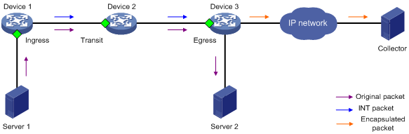
Figure 1 INT network diagram
Concepts
· Entry node
The entry node samples packets and mirrors sampled packets to the INT processor, adds an INT header and metadata to the packets, and sends them to the transit node.
· Transit node
The transit node identifies INT packets, adds metadata to the INT packets, and sends them to the exit node.
· Exit node
As the last hop in an INT network, the exit node identifies INT packets, adds metadata to the INT packets, encapsulates the UDP header and IP header for the INT packets, and sends them to the collector.
· Ingress port
For the entry node, this port is the input interface of original packets. For the transit node and exit node, this port is the input interface of INT packets.
· Egress port
For the entry node and transit node, this port is the output interface of INT packets. For the exit node, this port is the output interface of encapsulated packets.
· INT processor
The INT processor is a dedicated processor in the CPU used for processing INT packets. For the mirrored packets on the entry node, the INT processor adds an INT header to generate INT packets. On the exit node, the INT processor performs consistency checks on the encapsulation format of metadata and encapsulates the outer UDP header for the INT packets.
Metadata that INT can collect
INT can collect and monitor the following metadata:
· Device ID.
· Ingress port ID—Logical input interface of packets.
· Ingress timestamp—The local time on the device when a packet enters the ingress port. For the entry node, it is the time when an INT packet enters the loopback interface.
· Egress port ID—Logical output interface of packets
· Egress timestamp—The local time on the device when a packet leaves the egress port.
· Cache information:
¡ Queue ID—ID of the queue that caches original packets.
¡ ECN information.
INT packet types and packet formats
Packet types
INT has two packet types: INT over TCP and INT over UDP.
An original TCP packet is called an INT-over-TCP packet after it is mirrored and inserted with an INT header.
An original UDP packet is called an INT-over-UDP packet after it is mirrored and inserted with an INT header.
Figure 2 INT over TCP
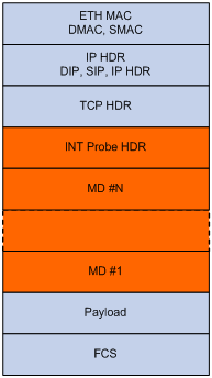
Figure 3 INT over UDP
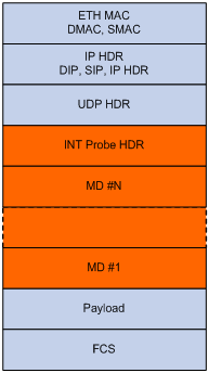
The following explains the meanings of related fields:
· INT Probe HDR—Header inherent to INT.
· MD #1-N—Inserted metadata.
Packet formats
An INT header contains two parts: an inherent header and metadata.
Figure 4 shows the format of the inherent header.
Figure 4 Inherent header format
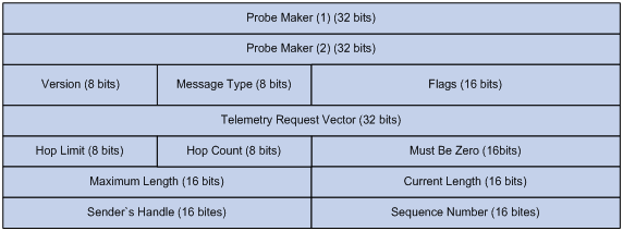
The following explains the meanings of the fields:
· Probe Marker—Used by the device to identify INT packets. Its value is fixed at 0xaaaaaaaabbbbbbbb.
· Version—Currently fixed at 0x01.
· Message Type—Currently fixed at 0x01.
· Flags—A reserved field, currently fixed at 0x0000.
· Telemetry Request Vector—Currently fixed at 0xffffffff.
· Hop Limit—Maximum number of hops allowed.
· Hop Count—Number of nodes the packet has traversed.
· Maximum Length—Maximum length of metadata that can be collected, in bytes.
· Current Length—Length of metadata that has been collected, in bytes.
· Sender's Handle—Set by the entry node for the collector to identify an INT flow and uniquely identifies an INT flow.
· Sequence Number—Sequence number of packet in an INT flow.
Figure 5 shows the format of the metadata.
Figure 5 Inherent header format
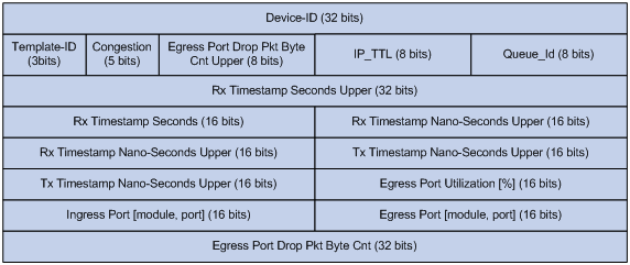
The following explains the meanings of the fields:
· Template-Id—A reserved field, currently fixed at 000.
· Congestion—Indicating the congestion state. The three most significant bits are fixed at 000, and the two least significant bits are the ECN field.
· Egress Port Drop Pkt Byte Cnt Upper—Drop count in bytes for the egress port, currently fixed at 0x00.
· IP_TTL—TTL value.
· Queue-Id—Egress queue ID, currently fixed at 0x00.
· Rx Timestamp Seconds Upper/Rx Timestamp Seconds— Ingress timestamp in seconds.
· Rx Timestamp Nano-Seconds Upper—Ingress timestamp in nanoseconds.
· Tx Timestamp Nano-Seconds Upper—Egress timestamp in nanoseconds.
· Egress Port Utilization [%]—Egress port utilization in percentage, currently fixed at 0x0000.
· Ingress Port [module, port]—Ingress port.
· Egress Port [module, port]—Egress port.
· Egress Port Drop Pkt Byte Cnt—Drop count in bytes for the egress port, currently fixed at 0x00000000.
Mechanism
INT-capable devices form an INT zone. Each INT device performs different functions in the INT zone.
· Entry node—By using a QoS policy on the ingress port, the entry node classifies incoming traffic and mirrors classified traffic to the INT processor. The INT processor adds the inherent INT header to matching packets, and adds metadata, and forwards the packets by looking up the routing table.
· Transit node—The transit node automatically identifies INT packets, adds metadata to them, and forwards them by looking up the routing table.
· Exit node—The transit node automatically identifies INT packets, sends the INT packets to the INT processor, and performs the following actions on the packets:
¡ Adds metadata.
¡ Encapsulates the outer UDP header for the INT packets.
¡ Encapsulates the outer IP header for the INT packets by using the configured encapsulation parameters.
¡ Routes the packet to the collector according to the destination IP address in the outer IP header.
Restrictions
Only the following switch series support INT:
· S6850.
· S9820.
· S9850.
· S12500X-AF T.
The following restrictions apply when you use INT on these switch series:
· The S9820 and S12500X-AF T switch series can act as only transit nodes.
· The S6850 and S9850 switch series can act as entry nodes, transit nodes, and exit nodes.
· If an S9850 switch acts as an entry node, you must enable internal loopback on an interface in the same port group as the ingress port. The interface enabled with internal loopback cannot be used for other purposes or configured with other settings. For port grouping conventions, execute the display drv system 9 command in probe view. Interfaces of the same pipe are in the same port group.
· For the S9820 switch series, Table 1 shows the mappings between ports on the front panel and the Ingress/Egress Port IDs in metadata.
Table 1 Mappings between ports on the front panel and the Ingress/Egress Port IDs in metadata
Ports on the front panel | Timestamp Port ID | Ingress/Egress Port ID | |
Port before splitting | Ports after splitting | ||
H1/0/1 | TW1/0/1:1 | 0 | 34 |
- | TW1/0/1:2 | 1 | 35 |
- | TW1/0/1:3 | 2 | 36 |
H1/0/2 | TW1/0/1:4 | 3 | 37 |
H1/0/3 | TW1/0/3:1 | 4 | 38 |
- | TW1/0/3:2 | 5 | 39 |
- | TW1/0/3:3 | 6 | 40 |
H1/0/4 | TW1/0/3:4 | 7 | 41 |
H1/0/5 | TW1/0/5:1 | 8 | 42 |
- | TW1/0/5:2 | 9 | 43 |
- | TW1/0/5:3 | 10 | 44 |
H1/0/6 | TW1/0/5:4 | 11 | 45 |
H1/0/7 | TW1/0/7:1 | 12 | 46 |
- | TW1/0/7:2 | 13 | 47 |
- | TW1/0/7:3 | 14 | 48 |
H1/0/8 | TW1/0/7:4 | 15 | 49 |
H1/0/9 | TW1/0/9:1 | 16 | 50 |
- | TW1/0/9:2 | 17 | 51 |
- | TW1/0/9:3 | 18 | 52 |
H1/0/10 | TW1/0/9:4 | 19 | 53 |
H1/0/11 | TW1/0/11:1 | 20 | 54 |
- | TW1/0/11:2 | 21 | 55 |
- | TW1/0/11:3 | 22 | 56 |
H1/0/12 | TW1/0/11:4 | 23 | 57 |
H1/0/13 | TW1/0/13:1 | 24 | 58 |
- | TW1/0/13:2 | 25 | 59 |
- | TW1/0/13:3 | 26 | 60 |
H1/0/14 | TW1/0/13:4 | 27 | 61 |
H1/0/15 | TW1/0/15:1 | 28 | 62 |
- | TW1/0/15:2 | 29 | 63 |
- | TW1/0/15:3 | 30 | 64 |
H1/0/16 | TW1/0/15:4 | 31 | 65 |
H1/0/17 | TW1/0/17:1 | 32 | 68 |
- | TW1/0/17:2 | 33 | 69 |
- | TW1/0/17:3 | 34 | 70 |
H1/0/18 | TW1/0/17:4 | 35 | 71 |
H1/0/19 | TW1/0/19:1 | 36 | 72 |
- | TW1/0/19:2 | 37 | 73 |
- | TW1/0/19:3 | 38 | 74 |
H1/0/20 | TW1/0/19:4 | 39 | 75 |
H1/0/21 | TW1/0/21:1 | 40 | 76 |
- | TW1/0/21:2 | 41 | 77 |
- | TW1/0/21:3 | 42 | 78 |
H1/0/22 | TW1/0/21:4 | 43 | 79 |
H1/0/23 | TW1/0/23:1 | 44 | 80 |
- | TW1/0/23:2 | 45 | 81 |
- | TW1/0/23:3 | 46 | 82 |
H1/0/24 | TW1/0/23:4 | 47 | 83 |
H1/0/25 | TW1/0/25:1 | 48 | 84 |
- | TW1/0/25:2 | 49 | 85 |
- | TW1/0/25:3 | 50 | 86 |
H1/0/26 | TW1/0/25:4 | 51 | 87 |
H1/0/27 | TW1/0/27:1 | 52 | 88 |
- | TW1/0/27:2 | 53 | 89 |
- | TW1/0/27:3 | 54 | 90 |
H1/0/28 | TW1/0/27:4 | 55 | 91 |
H1/0/29 | TW1/0/29:1 | 56 | 92 |
- | TW1/0/29:2 | 57 | 93 |
- | TW1/0/29:3 | 58 | 94 |
H1/0/30 | TW1/0/29:4 | 59 | 95 |
H1/0/31 | TW1/0/31:1 | 60 | 96 |
- | TW1/0/31:2 | 61 | 97 |
- | TW1/0/31:3 | 62 | 98 |
H1/0/32 | TW1/0/31:4 | 63 | 99 |
H1/0/33 | TW1/0/33:1 | 64 | 1 |
- | TW1/0/33:2 | 65 | 2 |
- | TW1/0/33:3 | 66 | 3 |
H1/0/34 | TW1/0/33:4 | 67 | 4 |
H1/0/35 | TW1/0/35:1 | 68 | 5 |
- | TW1/0/35:2 | 69 | 6 |
- | TW1/0/35:3 | 70 | 7 |
H1/0/36 | TW1/0/35:4 | 71 | 8 |
H1/0/37 | TW1/0/37:1 | 72 | 9 |
- | TW1/0/37:2 | 73 | 10 |
- | TW1/0/37:3 | 74 | 11 |
H1/0/38 | TW1/0/37:4 | 75 | 12 |
H1/0/39 | TW1/0/39:1 | 76 | 13 |
- | TW1/0/39:2 | 77 | 14 |
- | TW1/0/39:3 | 78 | 15 |
H1/0/40 | TW1/0/39:4 | 79 | 16 |
H1/0/41 | TW1/0/41:1 | 80 | 17 |
- | TW1/0/41:2 | 81 | 18 |
- | TW1/0/41:3 | 82 | 19 |
H1/0/42 | TW1/0/41:4 | 83 | 20 |
H1/0/43 | TW1/0/43:1 | 84 | 21 |
- | TW1/0/43:2 | 85 | 22 |
- | TW1/0/43:3 | 86 | 23 |
H1/0/44 | TW1/0/43:4 | 87 | 24 |
H1/0/45 | TW1/0/45:1 | 88 | 25 |
- | TW1/0/45:2 | 89 | 26 |
- | TW1/0/45:3 | 90 | 27 |
H1/0/46 | TW1/0/45:4 | 91 | 28 |
H1/0/47 | TW1/0/47:1 | 92 | 29 |
- | TW1/0/47:2 | 93 | 30 |
- | TW1/0/47:3 | 94 | 31 |
H1/0/48 | TW1/0/47:4 | 95 | 32 |
H1/0/49 | TW1/0/49:1 | 96 | 102 |
- | TW1/0/49:2 | 97 | 103 |
- | TW1/0/49:3 | 98 | 104 |
H1/0/50 | TW1/0/49:4 | 99 | 105 |
H1/0/51 | TW1/0/51:1 | 100 | 106 |
- | TW1/0/51:2 | 101 | 107 |
- | TW1/0/51:3 | 102 | 108 |
H1/0/52 | TW1/0/51:4 | 103 | 109 |
H1/0/53 | TW1/0/53:1 | 104 | 110 |
- | TW1/0/53:2 | 105 | 111 |
- | TW1/0/53:3 | 106 | 112 |
H1/0/54 | TW1/0/53:4 | 107 | 113 |
H1/0/55 | TW1/0/55:1 | 108 | 114 |
- | TW1/0/55:2 | 109 | 115 |
- | TW1/0/55:3 | 110 | 116 |
H1/0/56 | TW1/0/55:4 | 111 | 117 |
H1/0/57 | TW1/0/57:1 | 112 | 118 |
- | TW1/0/57:2 | 113 | 119 |
- | TW1/0/57:3 | 114 | 120 |
H1/0/58 | TW1/0/57:4 | 115 | 121 |
H1/0/59 | TW1/0/59:1 | 116 | 122 |
- | TW1/0/59:2 | 117 | 123 |
- | TW1/0/59:3 | 118 | 124 |
H1/0/60 | TW1/0/59:4 | 119 | 125 |
H1/0/61 | TW1/0/61:1 | 120 | 126 |
- | TW1/0/61:2 | 121 | 127 |
- | TW1/0/61:3 | 122 | 128 |
H1/0/62 | TW1/0/61:4 | 123 | 129 |
H1/0/63 | TW1/0/63:1 | 124 | 130 |
- | TW1/0/63:2 | 125 | 131 |
- | TW1/0/63:3 | 126 | 132 |
H1/0/64 | TW1/0/63:4 | 127 | 133 |
Application scenarios
Example: Configuring INT
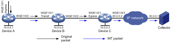
Network configuration
As shown in Figure 6, configure INT to test the link delay.
Procedure
1. Configure Device A:
# Create a sampler named samp in random sampling mode, and set the sampling rate to 8. One packet from 256 packets is selected.
<DeviceA> system-view
[DeviceA] sampler samp mode random packet-interval n-power 8
# Enable INT globally.
[DeviceA] telemetry ifa global enable
# Create a traffic class named classifier1, and use destination MAC address a08c-fdd7-fd99 as the match criterion in the traffic class.
[DeviceA] traffic classifier classifier1
[DeviceA-classifier-classifier1] if-match destination-mac a08c-fdd7-fd99
[DeviceA-classifier-classifier1] quit
# Create a traffic behavior named behavior1, and configure the action of mirroring traffic to the INT processor.
[DeviceA] traffic behavior behavior1
[DeviceA-behavior-behavior1] mirror-to ifa-processor sampler samp
[DeviceA-behavior-behavior 1] quit
# Create a QoS policy named ifa1, and associate traffic class classifier1 with traffic behavior behavior1 in the QoS policy.
[DeviceA] qos policy ifa1
[DeviceA-qospolicy-ifa1] classifier classifier1 behavior behavior1
[DeviceA-qospolicy-ifa1] quit
# Apply QoS policy ifa1 to the incoming traffic of Twenty-FiveGigE1/0/1.
[DeviceA] interface twenty-fivegige 1/0/1
[DeviceA-Twenty-FiveGigE1/0/1] qos apply policy ifa1 inbound
[DeviceA-Twenty-FiveGigE1/0/1] quit
# Specify 10.0.0.1 as the device ID of the entry node.
<DeviceA> system-view
[DeviceA] telemetry ifa device-id 10.0.0.1
# Specify Twenty-FiveGigE1/0/1 as the ingress interface.
[DeviceA] interface twenty-fivegige 1/0/1
[DeviceA-Twenty-FiveGigE1/0/1] telemetry ifa role ingress
[DeviceA-Twenty-FiveGigE1/0/1] quit
# Enable internal loopback on Twenty-FiveGigE1/0/3.
[DeviceA] interface twenty-fivegige 1/0/3
[DeviceA-Twenty-FiveGigE1/0/3] telemetry ifa role ingress
[DeviceA-Twenty-FiveGigE1/0/3] quit
| NOTE: This step is required only on the S9850 switch series. |
2. Configure Device B:
# Enable INT globally.
[DeviceB] telemetry ifa global enable
# Specify 10.0.0.2 as the device ID of the transit node.
<DeviceB> system-view
[DeviceB] telemetry ifa device-id 10.0.0.2
# Specify Twenty-FiveGigE 1/0/1 as the transit interface.
[DeviceB] interface twenty-fivegige 1/0/1
[DeviceB-Twenty-FiveGigE1/0/1] telemetry ifa role transit
[DeviceB-Twenty-FiveGigE1/0/1] quit
3. Configure Device C:
# Enable INT globally.
[DeviceC] telemetry ifa global enable
# Specify 10.0.0.3 as the device ID of the exit node.
<DeviceC> system-view
[DeviceC] telemetry ifa device-id 10.0.0.3
# Specify Twenty-FiveGigE 1/0/1 as the egress interface.
[DeviceC] interface twenty-fivegige 1/0/1
[DeviceC-Twenty-FiveGigE1/0/1] telemetry ifa role egress
[DeviceC-Twenty-FiveGigE1/0/1] quit
# Configure addressing parameters to encapsulate in INT packets sent to the collector.
[DeviceC] telemetry ifa collector source 20.0.0.2 destination 30.0.0.1 source-port 12 destination-port 14
Verify the configuration
# Verify the configuration on Device A.
[DeviceA] display qos policy interface twenty-fivegige 1/0/1 inbound
Interface: Twenty-FiveGigE1/0/1
Direction: Inbound
Policy: ifa1
Classifier: default-class
Matched : 0 (Packets) 0 (Bytes)
5-minute statistics:
Forwarded: 0/0 (pps/bps)
Dropped : 0/0 (pps/bps)
Operator: AND
Rule(s) :
If-match any
Behavior: be
-none-
Classifier: classifier1
Matched : 0 (Packets) 0 (Bytes)
5-minute statistics:
Forwarded: 0/0 (pps/bps)
Dropped : 0/0 (pps/bps)
Operator: AND
Rule(s) :
If-match destination-mac a08c-fdd7-fd99
Behavior: behavior1
Mirroring:
Mirror to the ifa-processor sampler samp
[DeviceA] display telemetry ifa
Telemetry ifa status: Enabled
Telemetry ifa device-id: 10.0.0.1
Telemetry ifa role:
Twenty-FiveGigE1/0/1: Ingress
Telemetry ifa loopback:
Twenty-FiveGigE1/0/3
# Verify the configuration on Device B.
[DeviceB] display telemetry ifa
Telemetry ifa status: Enabled
Telemetry ifa device-id: 10.0.0.2
Telemetry ifa role:
Twenty-FiveGigE1/0/1: Transit
# Verify the configuration on Device C.
[DeviceC] display telemetry ifa
Telemetry ifa status: Enabled
Telemetry ifa device-id: 10.0.0.3
Telemetry ifa role:
Twenty-FiveGigE1/0/1: Egress
Telemetry ifa collector:
Source IP: 20.0.0.2
Destination IP: 30.0.0.1
Source-port: 12
Destination-port: 14
