| Title | Size | Downloads |
|---|---|---|
| H3C UIS Manager Cloud Rainbow Configuration Guide-5W101-book.pdf | 2.26 MB |
- Table of Contents
Cloud Rainbow Configuration Guide
Document version: 5W101-20210103
Copyright © 2021 New H3C Technologies Co., Ltd. All rights reserved.
No part of this manual may be reproduced or transmitted in any form or by any means without prior written consent of New H3C Technologies Co., Ltd.
Except for the trademarks of New H3C Technologies Co., Ltd., any trademarks that may be mentioned in this document are the property of their respective owners.
The information in this document is subject to change without notice.
About cloud rainbow
Cloud rainbow provides UIS resource sharing and manual VM migration between data centers without service interruption.
Restrictions and guidelines
· Do not connect hosts to any UIS Manager during VM migration.
· For successful VM migration, make sure the distance between the data centers where the two UIS Managers are located is no longer than 30 km (18.64 miles).
· As a best practice, use 10-GE link aggregation or directly connect the two UIS Managers with fibers. Make sure the UIS Managers are reachable to each other at Layer 3.
· As a best practice, migrate VMs when memory change is not so frequent, because online VM migration requires frequent VM memory synchronization.
· For cloud rainbow to take effect, make sure the source and destination resource pools have port profiles and vSwitches with the same names.
· VMs that have optical drives, floppy disks, PCIs, USB devices, or block devices attached cannot be migrated.
· Service interruption might occur during the last phase of online VM migration. For example, if you continuously ping the IP address of the VM being migrated, the number of dropped packets will be 0 to 2, depending on the memory usage and memory change of the VM.
· The VM console will be disconnected after a VM is migrated to the destination UIS Manager, because the IP address and VNC port of the CVK host attached to the VM changed after migration.
· The IP address of a VM does not change after migration no matter whether this IP address is a static or DHCP-assigned IP address.
· For successful migration of a VM whose data cache mode is None or Directsync and whose disk is in an NFS, shut down the VM before migration.
Hardware and software requirements
Hardware requirements
This document is not restricted to a specific server model. The configuration in this document might differ from the configuration in actual deployment.
The hardware used in this document is shown in Table 1. The hardware requirements are not intended to be mandatory or recommended during actual deployment. You can complete configuration as long as your server is compatible with H3C UIS Manager.
Table 1 Local site hardware requirements
|
Hardware |
Requirements |
|
Server model |
H3C R4900 G3 |
|
Server quantity |
3 |
|
CPU |
2 × 12-core Intel(R) Xeon(R) Silver 4116 CPU @ 2.10GHz CPUs |
|
Memory |
128 GB |
Table 2 Remote site hardware requirements
|
Hardware |
Requirements |
|
Server model |
H3C R4900 G3 |
|
Server quantity |
4 |
|
CPU |
2 × 12-core Intel(R) Xeon(R) Silver 4116 CPU @ 2.10GHz CPUs |
|
Memory |
128 GB |
Software requirements
|
Software |
Version |
|
H3C UIS |
E0709 |
Network diagram
Figure 1 H3C UIS cloud rainbow network diagram

Procedure
Creating a VM
1. Log in to the UIS manager of the local data center.
2. Click VMs on the top navigation bar, and then click Add.
Figure 2 VMs in the local data center

3. Configure the VM settings as described in Table 3, and then click Finish.
Figure 3 Configuring VM parameters

|
Item |
Requirements |
|
CPUs |
2 socket 4 cores |
|
Memory size |
4 GB |
|
Disk size |
80 GB (local disk) |
|
Bus type |
Use the default setting (1 × Virtio, high-speed) |
|
Storage format |
Use the default setting (QCOW2) |
|
Disk caching mode |
Use the default setting (directsync) |
|
vNIC type |
Use the default setting (1 × Virtio) |
|
vSwitch |
Use the default setting (vSwitch0) |
|
Port profile |
Use the default setting |
|
IP address/subnet mask |
172.20.185.159/16 |
|
|
IMPORTANT: The settings in Table 3 are configured for a test environment. In a production environment, you must configure VM settings such as CPU, memory, disk, NIC, OS, and custom settings such as disk partition, account, and component installation based on the actual requirements of your system. |
4. Start the VM and install an operating system for the VM.
Figure 4 Installing an operating system for the VM

5. Install CAStools for the VM.
Figure 5 Installing CAStools

Figure 6 Installing CAStools for the VM

6. Configure IP address settings for the VM manually or through CAStools.
Figure 7 Configuring IP address settings for the VM

7. During VM migration, download files from an FTP server to verify that VM service is not affected when the VM is being migrated.
Make sure an FTP client has been installed on the operating system of the VM.
Figure 8 Verifying VM service state during migration

Performing online VM migration
1. On the top navigation bar, click Services, and then select Cloud Rainbow from the navigation pane.
2. Click the Add icon ![]() .
.
If you add a UIS Manager for the first time, a dialog box opens and prompts you to configure the local data center. Click OK in the dialog box, and then configure the local data center parameters.
Figure 9 Local data center

3. Specify a name for the local data center, and the enter the management IP address of the UIS Manager, and then click OK.
Figure 10 Configuring the local data center

4. On the top navigation bar, click Services, and then select Cloud Rainbow from the navigation pane.
5. Click the Add
icon ![]() to the right of the page.
to the right of the page.
6. Configure the parameters as described in Table 4, and then click OK:
Figure 11 Adding a remote data center

Table 4 Data center parameters
|
Parameter |
Description |
|
Name |
Specify a name for the data center. A maximum of 36 Chinese or English characters. Required. |
|
Description |
Specify a description for the data center. A maximum of 120 Chinese or English characters. Optional. |
|
IP Address |
Enter the IP address of the data center. It must be an IPv4 address in dotted decimal notation. Required. |
|
Login Mode |
Select a method for logging in to the data center. Required. |
|
Port |
Enter the port number for accessing the data center. If HTTP is used, the default port number is 8080. If HTTPS is used, the default port number is 8443. Required. |
|
Username |
Enter the username for accessing the data center. Required. |
|
Password |
Enter the password for accessing the data center. A maximum of 32 Chinese or English characters. Required. |
The system displays both the local data center and remote data center.
Figure 12 Local and remote data centers topology

7. Enter a VM alias in the search box, and then press Enter or double click a host to view all VMs on the host, and then drag the target VM to the destination host on the remote UIS Manager.
Figure 13 Viewing VM information

Figure 14 Manually migrating the VM to the remote data center

8. In the configuration box that opens, configure the parameters as needed, and then click Next.
¡ Timeout: Enter the migration timeout for migrating running VMs. The system suspends a VM if the VM cannot be migrated before the timeout timer expires and restores the VM after migration.
¡ Compress: Select this option to compress the data to be transmitted.
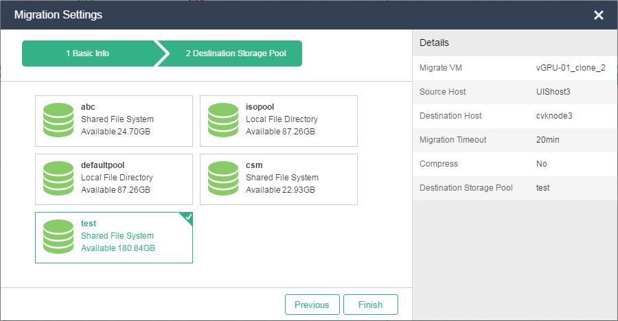
9. Select the destination storage pool, and then click Finish.
Figure 15 Selecting the destination storage pool
10. Open the task console to view VM migration progress.
Figure 16 Viewing VM migration progress from the task console

11. On a VM or PC that is reachable to the VM being migrated at Layer 3, ping the IP address of the VM to view the VM state during migration.
Figure 17 Viewing VM migration state

12. Verify the migration result:
a. On the task console, view the migration progress, which is 100%. Then log in to the UIS Manager in the remote data center to view the VM state. The system displays that the VM is in running state, and its IP address does not change.
Figure 18 Viewing information about the VM after migration through cloud rainbow

b. View cloud rainbow VM migration operation log in the UIS Manager operation log list.
Figure 19 Viewing VM migration operation log

c. Log in to the remote UIS Manager, and access the migrated VM from the console. The system displays that FTP download is being performed on the VM's operating system.
Figure 20 Viewing the state of the migrated VM through FTP